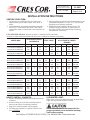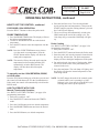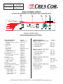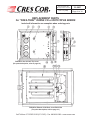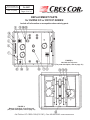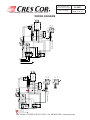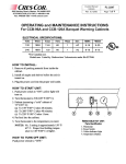
1
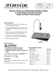
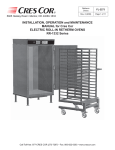
5925 Heisley Road • Mentor, OH 44060-1833
Ovens Humidity with
Microprocessor Controls
FL-2267
Rev. 13 (3/08)
Page 1 of 14
INSTALLATION, OPERATION and MAINTENANCE
MANUAL for Cres Cor AQUATEMP HUMIDITY
CONVECTION and RETHERM OVENS with
MICROPROCESSOR CONTROLS
RO151FW1332B-Q1
CO151FWUA12B-Q1
RO151FWUA18B-Q1
CO151XWUA5B-Q1
CO151HWUA6B-Q1
CO151FPWUA12B-Q1
RO151FPWUA18B-Q1
Call Toll-free: 877-CRES COR (273-7267) • Fax: 800-822-0393 • www.crescor.com
Ovens Humidity with
Microprocessor Controls
FL-2267
Rev. 13 (3/08)
Page 2 of 14
5925 Heisley Road • Mentor, OH 44060-1833
TABLE OF CONTENTS
SUBJECT
PAGE
INSTALLATION INSTRUCTIONS….........................…...…………….....…...……..…...…..3
OPERATING INSTRUCTIONS…………………………..……………....…………..….4, 5, 6
Illustration, Figure 1………………………………..……………........……….………...4
MAINTENANCE INSTRUCTIONS
How to Clean the Unit………………………………....…………........………..…...…..7
Trouble Shooting Guide……………………………...……….....…....……...….……8, 9
Replacement Parts………………………………………....…….…......……….…...9, 10
Illustrations; Hot Unit…………….………………………...……....…………........11, 12
Wiring Diagrams………………………...…………………..…......……....…………..13
OPTIONAL PRODUCT KEYS…………………...……………..….........……..........………14
TIMER PROGRAMMING…….……………………………………..………...……...FL-2222
SERVICE POLICY and AGENCY LIST…………………………….….....….……….FL-1400
WARNING
RISK OF FIRE OR ELECTRIC SHOCK
DO NOT OPEN
WARNING: TO REDUCE THE RISK OF FIRE OR ELECTRIC SHOCK,
DO NOT REMOVE COVER (OR BACK)
NO USER-SERVICEABLE PARTS INSIDE
REPAIR SHOULD BE DONE BY AUTHORIZED SERVICE
PERSONNEL ONLY
Call Toll-free: 877-CRES COR (273-7267) • Fax: 800-822-0393 • www.crescor.com
Ovens Humidity with
Microprocessor Controls
FL-2267
Rev. 13 (3/08)
Page 3 of 14
5925 Heisley Road • Mentor, OH 44060-1833
INSTALLATION INSTRUCTIONS
VENTING YOUR OVEN:
3. Most jurisdictions consider our low-temperature ovens
(maximum temperature is 350°F/177°C) as low-heat
appliances not requiring vent hoods.
4. Installation must conform with local codes. The
authority having jurisdiction of enforcement of
the codes will have the responsibility for making
interpretations of the rules.
1. The purpose of ventilating hoods is to direct and
capture smoke, grease-laden vapors, heat, odors, or
fumes.
2. Low temperature equipment (maximum temperature
250°F/121°C) does not produce heat, odors, fumes,
grease-laden vapors or smoke and is not required to be
vented.
UNIT SPECIFICATIONS: All units use three (3) elements (2670 watts each).
All units are rated 8200 watts. Water units have one (1) immersion element (1850 watts).
MODEL NOS.
CONVECTION OVENS
ELECTRICAL SPECS
(AC SERVICE)
ELEC. LOAD
POWER SUPPLY REQUIREMENT
ALL 3 PHASE IS 3 WIRE +
GROUND
Volts
Ph
Hz.
Amps
Volts
Amps
Ph
Volts
NEMA
CO151FWUA12B2081Q1
CO151FWUA12B2401Q1
208
240
1
1
60
60
39
34
208
240
50
50
1
1
208
240
6-50P
6-50P
CO151FWUA12B2083Q1
CO151FWUA12B2403Q1
208
240
3
3
60
60
23
20
208
240
30
30
3
3
208
240
L15-30P
L15-30P
RO151FWUA18B2081Q1
RO151FWUA18B2401Q1
208
240
1
1
60
60
39
34
208
240
50
50
1
1
208
240
6-50P
6-50P
RO151FWUA18B2083Q1
RO151FWUA18B2403Q1
208
240
3
3
60
60
23
20
208
240
30
30
3
3
208
240
L15-30P
L15-30P
RO151FW1332B2081Q1
RO151FW1332B2401Q1
208
240
1
1
60
60
39
34
208
240
50
50
1
1
208
240
6-50P
6-50P
RO151FW1332B2083Q1
RO151FW1332B2403Q1
208
240
3
3
60
60
23
20
208
240
30
30
3
3
208
240
L15-30P
L15-30P
RETHERM OVENS
HALF-SIZE OVENS Are rated at 4950 watts (three [3] heaters at 1470 watts each)
CO151HWUA6B2081Q1
CO151HWUA6B2401Q1
208
240
1
1
60
60
24
21
208
240
30
30
1
1
208
240
6-30P
6-30P
CO151HWUA6B2083Q1
CO151HWUA6B2403Q1
208
240
3
3
60
60
15
13
208
240
20
20
3
3
208
240
L15-20P
L15-20P
CO151XWUA5B2081Q1
CO151XWUA5B2401Q1
208
240
1
1
60
60
24
21
208
240
30
30
1
1
208
240
6-30P
6-30P
CO151XWUA5B2083Q1
CO151XWUA5B2403Q1
208
240
3
3
60
60
15
13
208
240
20
20
3
3
208
240
L15-20P
L15-20P
HOW TO INSTALL CABINETS:
1. Remove all packing material from inside and outside
of cabinet.
2. Position cabinet on level floor; install the cabinet
interior (pan slides) if not already installed.
3. Plug power cord into proper wall receptacle.
4. Fill water pan with three (3) gallons of HOT water
(see CAUTION).
LOW WATER LIGHT:
When water needs to be added to the pan, the Low Water
Light will stay on until the pan is refilled.
Use of treated water is recommended for
proper operation and to maintain warranty.
It will reduce scaling.
Call Toll-free: 877-CRES COR (273-7267) • Fax: 800-822-0393 • www.crescor.com
Ovens Humidity with
Microprocessor Controls
FL-2267
Rev. 13 (3/08)
Page 4 of 14
5925 Heisley Road • Mentor, OH 44060-1833
OPERATING INSTRUCTIONS
COOKING/HOLDING
CONTROL
POWER SWITCH
HUMIDITY
CONTROL
TM
Roast-N-Hold +
R
ON
MODE
(I)
TIME / TEMPERATURE
5
SETPOINTS
4
PROBE
SELECT
6
COOK
TIMED
HEAT
COOK
HOLD
PROBE
TIME
SET
MEDIUM
7
3
8
LOW
OFF
(0)
START
STOP
LOW
WATER
HIGH
2
OVEN
TEMP
9
HOLD
DRY
MOIST
1
10
HUMIDITY
POWER
Figure 1: Control Panel
HOW TO START UNIT:
COOKING TEMPERATURE:
(for first-time operation only)
A new oven needs to “burn off” factory oils and glue
before it’s first use. Do NOT load food into oven until this
has been done!
1. Push power switch to “ON”.
2. Press the SELECT button; choose the TIMED mode.
3. Press the COOK button and set the temperature to
350°F/177°C.
4. Press the HOLD button and set the temperature to
150°F/66°C.
5. Press the PROBE/TEMP button and set the timer to
one (1) hour.
6. Allow oven to run automatically for one (1) hour of
COOK/RETHERM cycle and 30 minutes of HOLD
cycle.
NOTE: Press the OVEN TEMP button at any time to
view the actual oven temperature.
HOW TO SET THE CONTROL
NOTE: Proper food holding temperature is 140°F/60°C
or higher.
FOR TIMED COOK OPERATION:
Press the SELECT button to choose the TIMED mode.
COOKING TIME:
1. Press the PROBE/TIME button. The display will show
the cook/retherm time.
2. Use the UP and DOWN arrows to set the desired time.
3. Press the SET button to enter the time into the control.
NOTE: Cold food is NOT to be added when unit is
operating in HOLD mode.
1. Press the COOK button and the display will show the
cook/retherm temperature.
2. Use the UP and DOWN arrows to set the desired
temperature.
3. Press the SET button to enter the temperature into the
control.
HOLDING TEMPERATURE:
1. Press the HOLD button; the display will show the
holding temperature.
2. Use the UP and DOWN arrows to set the desired
temperature.
3. Press the SET button to enter the temperature into the
control.
4. Press the START button and the display shows the
remaining time in the cook/retherm cycle.
NOTE: The control will beep after it times down to zero;
it will then automatically switch to the HOLD
mode. The display will then show the hold
setpoint temperature. For HOLD mode, preheat
unit to 180°F/82°C for 60 minutes.
Call Toll-free: 877-CRES COR (273-7267) • Fax: 800-822-0393 • www.crescor.com
5925 Heisley Road • Mentor, OH 44060-1833
Ovens Humidity with
Microprocessor Controls
FL-2267
Rev. 13 (3/08)
Page 5 of 14
OPERATING INSTRUCTIONS, continued
HOW TO SET THE CONTROL, continued
FOR PROBE COOK OPERATION:
Press the SELECT button to choose the probe mode.
PROBE TEMPERATURE:
1. Press the PROBE/TIME button. The display will show
the probe setpoint temperature.
2. Use the UP and DOWN arrows to set the desired
temperature.
3. Press the SET button to enter the temperature into the
control.
NOTE: Press the OVEN TEMP button at any time to
view the actual oven temperature. Press the
START button and the display will show the
actual probe temperature.
NOTE: The control will beep when the probe setpoint
temperature has been reached and then will
automatically switch to HOLD mode. The
display will then show the hold setpoint
temperature.
To manually end the COOK/RETHERM, PROBE,
or HOLD mode:
Press the STOP button during any of the above modes and
the control will end that mode. If in the Cook/Retherm or
Probe mode, the control will automatically switch into the
HOLD mode.
6. Place the food into oven. Close door and double
check cooking time and temperatures. Then press the
START button to start the cooking/retherm cycle and
the Cook LED will light up.
7. The oven will beep and automatically switch to the
HOLD mode at the end of the cooking cycle. The
Cook lamp will go out and the Hold lamp will light
up.
Probe Cooking
See “HOW TO SET THE CONTROL” (on page 5) for
programming instructions.
1. Push power switch to “ON”.
2. Press the SELECT button and choose the Probe mode.
3. Insert the probe jack into the receptacle located inside
the oven top, near the fans. The probe temperature
display will show the digital temperature of the probe.
4. Put sanitized probe into center of food product. Make
sure food is in the center of the pan and the pan is
centered in the oven.
5. Press the start button. The cook lamp will light up and
the display will show the internal temperature of the
food being cooked.
NOTE: Do NOT change the mode of the controls (probe
or timed) while oven is operating in a Cook/
Retherm cycle. Oven must be in the HOLD cycle
to change the timer or probe operation.
HOW TO OPERATE WITH FOOD:
Manual (Timed mode) Operation
See “HOW TO SET THE CONTROL” (on page 4) for
programming instructions.
1. Push power switch to “ON”.
2. Press the SELECT button and choose the TIMED
mode.
3. Press the COOK button and set to desired temperature.
4. Press the PROBE/TIME button and set to the desired
time.
5. Press the HOLD button; set desired temperature.
Call Toll-free: 877-CRES COR (273-7267) • Fax: 800-822-0393 • www.crescor.com
Ovens Humidity with
Microprocessor Controls
FL-2267
Rev. 13 (3/08)
Page 6 of 14
5925 Heisley Road • Mentor, OH 44060-1833
OPERATING INSTRUCTIONS, continued
HOW TO OPERATE WITH HUMIDITY:
HOW TO OPERATE WITH FOOD, continued
HOW TO SET HOLD-ONLY MODE:
1. Push power switch to “ON”.
2. Press the STOP button and oven will switch to HOLD
cycle.
3. Press the HOLD button and set the desired hold
temperature.
NOTE: Cold food is NOT to be added when unit is
operating in HOLD mode.
WARNING
Air is VERY HOT when door is opened.
Humidity control is on the right of the control panel
(see Figure 1).
Humidity may be used in all control modes.
For HOLD mode, preheat unit to 180°F/82°C for
60 minutes.
Turn control knob to extreme counter-clockwise
position when humidity is not needed.
Make sure there is water in the water pan.
HOW TO PROOF:
1. Fill the water pan with three (3) gallons of HOT water.
2. Set the humidity control at low to mid-range.
3. Set the Hold control to Nominal 120°F/49°C.
HOW TO SHUT DOWN OVEN:
Push switch to “OFF”.
Ventilating fans will continue to run until the cabinet is
cool. Do NOT disconnect the power supply to the cabinet
while the ventilating fan is still operating.
4. Preheat the oven at this setting for ½ hour.
5. Put in product. DO NOT use frozen product.
Listed below are typical thermostat settings. Experiment with different settings to get the
temperature and humidity you need.
TEMPERATURE / HUMIDITY SETTINGS
HOLD
Dial Setting
Temp.,°F/°C
1
2
140/60
15
20
150/66
10
15
160/71
5
10
180/82
5
5
200/93
5
5
Values Listed are % Relative Humidity.
3
25
20
15
10
5
4
35
25
20
15
10
HUMIDITY
Dial Setting
5
6
50
65
35
55
30
40
20
25
15
20
7
85
70
60
30
25
8
100
100
80
50
35
9
100
100
100
70
50
Call Toll-free: 877-CRES COR (273-7267) • Fax: 800-822-0393 • www.crescor.com
10
100
100
100
95
75
5925 Heisley Road • Mentor, OH 44060-1833
Ovens Humidity with
Microprocessor Controls
FL-2267
Rev. 13 (3/08)
Page 7 of 14
MAINTENANCE INSTRUCTIONS
HOW TO CLEAN THE UNIT
MAINTENANCE: WATER PAN
MAINTENANCE: CABINET
Drain, wipe and fill water pan daily.
1. Wipe the inside of cabinet after daily use.
(Clear vinyl drain-hose is provided).
1. Push hose onto drain nozzle under the base.
2. Turn knob to open the drain.
2. Leave doors slightly open to fully dry interior.
To Fully Dry Out:
1. Drain until 1/8” of water is left in pan bottom.
2. Turn humidity Thermostat to “High” until water is
gone.
3. Wipe out pan.
WARNING
BEFORE cleaning the cabinet:
1. Unplug cord from wall. Allow cabinet to
cool.
2. Do NOT hose cabinet with water.
Delime or descale water pan parts as required,
to prevent damaging build-up.
WARRANTY COVERAGE MAY BE AFFECTED
WITHOUT PROPER CLEANING.
3. Do NOT get water on controls.
Cleaning Hints:
3. Use only a soft cloth, sponge, fibrous brushes, plastic
or stainless steel pad for cleaning and scouring.
1. Use the mildest cleaning procedure that will do the
job.
2. Always rub in the direction of the polish lines to avoid
scratching the surface.
4. Do NOT use abrasives or harsh
chemicals.
4. Rinse thoroughly with fresh water after every cleaning
operation.
5. Always wipe dry to avoid water marks.
HOW TO CLEAN THE UNIT:
CABINET
SOIL
CLEANER
METHOD
ROUTINE CLEANING
Soap, ammonia or mild
detergent* and water.
1. Sponge on with cloth
2. Rinse
STUBBORN SPOTS,
STAINS
Mild abrasive made for
Stainless Steel.
1. Apply with damp sponge or cloth.
2. Rub lightly.
BURNT ON FOODS OR
GREASE
Chemical oven cleaner
made for Stainless Steel.
Follow oven cleaner manufacturer’s
directions.
HARD WATER SPOTS &
SCALE
Vinegar
1. Swab or wipe with cloth.
2. Rinse and dry.
Inside and Outside
(Stainless Steel)
* Mild detergents include soaps and non-abrasive cleaners
Call Toll-free: 877-CRES COR (273-7267) • Fax: 800-822-0393 • www.crescor.com
Ovens Humidity with
Microprocessor Controls
FL-2267
Rev. 13 (3/08)
Page 8 of 14
5925 Heisley Road • Mentor, OH 44060-1833
MAINTENANCE INSTRUCTIONS
TROUBLE-SHOOTING GUIDE
WARNING
IF UNIT GETS TOO HOT OR WON’T SHUT OFF, DISCONNECT
POWER AT BRANCH PANEL. DO NOT UNPLUG CORD!
If hot unit is NOT working, first check the following causes:
1. Cord is unplugged from wall outlet.
2. Circuit breaker/fuse to wall outlet is blown.
PROBLEM
3. Switch is turned off.
4. Thermostat is turned off, or is set too low.
Vent fans do not shut off
1. Vent fan switch defective
2. Control compartment is still hot.
Vent fans do not operate (See Note)
1. Fuse
2. Vent fan switch defective
3. Vent fan defective
SOLUTION
1. Replace
2. Replace
3. Replace
4. Replace
5. Replace
6. Replace
1. Replace
2. Replace
3. Replace
4. Replace
1. Replace
1. Replace
2. Wait until it cools
Check “Heater will not shut off”
1. Replace
2. Replace
3. Replace
Control will not switch from “COOK” to
“HOLD” (timer mode)
1. Oven is in “PROBE” mode.
2. Control defective
1. Switch to “TIMED” mode
2. Replace
Control will not switch from “COOK” to
“HOLD” (probe mode)
1. Oven is in the “TIMED” mode
2. Probe not plugged in
3. Control defective
1. Switch to “PROBE” mode
2. Plug in probe
3. Replace
1. Oven in “TIMED” mode
2. Probe temperature setting lower than
probe temperature
3. Probe not plugged in
4. Control defective
1. Water element defective
2. Humidity control
1. Switch to “PROBE” mode
2. Set probe temperature to desired
temperature
3. Plug in probe
4. Replace
1. Replace
2. Replace
Cabinet does not heat, or doesn’t heat
properly
Blowers do not operate
Heater will not shut off
Control will not switch to “COOK” (probe
mode)
No Humidity
POSSIBLE CAUSE
1. Fuse
2. Control
3. Sensor
4. Heater contactor
5. Loose wiring at heater contactor
6. On/Off Switch
1. On/Off Switch
2. Fuse
3. Blower
4. Control
1. Control defective
NOTE: Vent fans will not operate until the control compartment requires ventilation to limit temperatures. Replacement
of electrical components must be done by a qualified electrician.
Refer to our Service Agency list, FL-1400 (found in the back of this manual), of authorized service centers.
Instructions for replacing parts are included in replacement parts list.
Call Toll-free: 877-CRES COR (273-7267) • Fax: 800-822-0393 • www.crescor.com
Ovens Humidity with
Microprocessor Controls
FL-2267
Rev. 13 (3/08)
Page 9 of 14
5925 Heisley Road • Mentor, OH 44060-1833
MAINTENANCE INSTRUCTIONS
TROUBLE-SHOOTING GUIDE, continued
HOW TO ADJUST THE DOOR LATCH:
1. For vertical (up and down movement) adjustment:
a. Loosen (2) screws located in magnetic strike.
b. Move strike up or down for alignment to magnet on
latch.
c. Tighten screws to secure
2. For horizontal (greater or lesser magnetic draw)
adjustment:
a. Loosen (4) screws in door latch.
b. Move latch forward or backward to adjust
magnetism.
c. Tighten screws to secure.
HOT UNIT REMOVAL:
1. Disconnect power cord from wall outlet.
2. For half-size model: CO151HW Series, remove
screws around top cover.
3. Disconnect the yellow cord between top and bottom,
in the back of the cabinet (see Figure 2).
4. Lift off Hot Unit.
FIGURE 2
HOT UNIT REMOVAL
REPLACEMENT PARTS: Include all information on nameplate when ordering parts.
Cabinet Replacement Parts
MODEL PREFIX CO-151, RO-151 (“Q” SERIES)
DESCRIPTION
-FPWUA (12), (18)
-FWUA (12), (18)
-FW1332
-HWUA6
-XWUA5
Hot Unit, 208V, 1 Ph
HU675013Q1
HU675025Q1
HU675029Q1
HU675037Q1
HU675037Q1
Hot Unit, 208V, 3 Ph
HU675015Q1
HU675027Q1
HU675031Q1
HU675039Q1
HU675039Q1
Hot Unit, 240V, 1 Ph
HU675014Q1
HU675026Q1
HU675030Q1
HU675038Q1
HU675038Q1
Hot Unit, 240V, 3 Ph
HU675016Q1
HU675028Q1
HU675032Q1
HU675040Q1
HU675040Q1
Door Latch Kit
1006-120-001-K
1006-120-01-K
1006-120-001-K
1006-120-01-K
1006-120-01-K
Door Strike
1006-120-02-K
1006-120-02-K
1006-120-02-K
1006-120-02-K
1006-120-02-K
Door Hinge
0519-074-K
0519-074-K
0519-074-K
0519-074-K
0519-074-K
Door Assembly
1221-525-K
1221-525-K
1221-543
1221-525-K
1221-545-K
Door Gasket
0861-185-K
0861-185-K
0861-184
0861-185-K
0861-250-K
0621-281-SS-K
0621-281-SS-K
1104-108
0621-281-SS-K
0621-281-SS-K
0911-102
0911-102
0911-102
0911-102
0911-102
Angles or Racks
Side Handles (2),
Black Recessed
Call Toll-free: 877-CRES COR (273-7267) • Fax: 800-822-0393 • www.crescor.com
Ovens Humidity with
Microprocessor Controls
FL-2267
Rev. 13 (3/08)
Page 10 of 14
5925 Heisley Road • Mentor, OH 44060-1833
REPLACEMENT PARTS
Include all information on nameplate when ordering parts
1
2
16
18
17
TM
Roast-N-Hold +
R
ON
MODE
(I)
TIME / TEMPERATURE
5
SETPOINTS
4
PROBE
SELECT
6
COOK
TIMED
HEAT
COOK
HOLD
PROBE
TIME
SET
MEDIUM
7
3
8
LOW
OFF
OVEN
TEMP
(0)
START
STOP
LOW
WATER
HIGH
2
9
HOLD
DRY
MOIST
1
10
HUMIDITY
POWER
FIGURE 2: CONTROL PANEL
Hot Unit Replacement Parts
ITEM DESCRIPTION
1. Switch (On/Off)
2. Thermostat/Timer, Cooking/
Holding
3. Vent Fan
4. Fan Guard
5. Fuse
Fuse Holder
6. Blower Kit
7. Contactor
8. Terminal Block, front
9. Terminal Block, rear
10. Switch, Fan
11. Hi Limit Switch (Pass-thru)
Hi Limit Switch
12. Sensor
13. Sensor Bushing
14. Connector, probe
Probe 1.5” long
Probe 6” long
15. Relay
16. Thermostat, Humidity
17. Knob, Humidity Thermostat
18. Pilot Light
19. Receptacle (6 pin)
20. Resistor (For Relay)
• Float Switch
• Water Pan Kit, 208V
• Heater, 208V
• Water Pan Kit, 240V
• Heater, 240V
Part No.
0808-113-01-K
0848-070-03
0769-174
0769-167
0807-058
0807-048
0769-182-01-SSK
0857-026
0852-096
0852-091
0848-034
0848-077
0848-079
0848-073-01
0818-014
0848-059-01
0848-059-02
0848-059-04
0857-125-K
0848-008-1-AC
0595-061
0766-095
0810-154-02
0857-129
0857-122
0756-030-K
0811-278
0756-031-K
0811-271
ITEM DESCRIPTION
PARTS for 8200W, 1-PH UNITS
21. Power Cord
Power Cord (Pass-thru)
22. Heater Kit, 208V
Heater Kit, 240V
23. Strain Relief
Part No.
0810-124
0810-161
0811-261
0811-262
0818-061
PARTS for 8200W, 3-PH UNITS
21. Power Cord
Power Cord (Pass-thru)
22. Heater Kit, 208V
Heater Kit, 240V
23. Strain Relief
0810-132
0810-162
0811-261
0811-262
0818-050
PARTS for 4950W, 1-PH UNITS
21. Power Cord
22. Heater Kit, 208V
Heater Kit, 240V
23. Strain Relief
0810-163
0811-020-K
0811-020-01-K
0818-050
PARTS for 4950W, 3-PH UNITS
21. Power Cord
22. Heater Kit, 208V
Heater Kit, 240V
23. Strain Relief
0810-164
0811-020-K
0811-020-01-K
0818-050
Call Toll-free: 877-CRES COR (273-7267) • Fax: 800-822-0393 • www.crescor.com
5925 Heisley Road • Mentor, OH 44060-1833
Ovens Humidity with
Microprocessor Controls
FL-2267
Rev. 13 (3/08)
Page 11 of 14
REPLACEMENT PARTS
for “PASS-THRU” OVENS CO or RO151FPUA SERIES
Include all information on nameplate when ordering parts
FIGURE 3; Hot Unit w/o Top cover
(For parts description, refer to page 10.)
FIGURE 4; Bottom of Hot Unit, Cover Removed
(For parts description, refer to page 10.)
Call Toll-free: 877-CRES COR (273-7267) • Fax: 800-822-0393 • www.crescor.com
Ovens Humidity with
Microprocessor Controls
FL-2267
Rev. 13 (3/08)
Page 12 of 14
5925 Heisley Road • Mentor, OH 44060-1833
REPLACEMENT PARTS
for OVENS CO or RO151F SERIES
Include all information on nameplate when ordering parts
FIGURE 3;
Hot Unit w/o Top cover
(For parts description, refer to page 10.)
FIGURE 4;
Bottom of Hot Unit, Cover Removed
(For parts description, refer to page 10.)
Call Toll-free: 877-CRES COR (273-7267) • Fax: 800-822-0393 • www.crescor.com
G
L2
L1
1 PHASE
16
15
13
2
1
RELAY
18
A
9
8
7
5
B
6
3
5
2
4
1
HEATER
CONTACTOR
19
6
BLACK
WHITE
R=47K
17
14
8
6
7
7
2
FUSE
13
HIGH LIMIT
FUSE
3
4
17
11
8
9
12
14
H3
H2
H1
SINGLE PHASE
HIGH LIMIT
1
V
10
V
18
L
R
C
BM
22
38
A
32
BM
33
HIGH TEMP
ORANGE
BM
24
20
9
8
36
39
4
5
19
38
6
7
GREEN
RED
ORANGE
BLACK
WHITE
BLUE
GREEN
RED
ORANGE
BLACK
WHITE
BLUE
Water Thermostat
10
37
24
21
5
35
32
34
FLOAT
SWITCH
t°
t°
HEAT
A
110v
26
220v
31
28
SENSOR
WATER
HEATER
WATER
240V
SENSOR
WATER
HEATER
WATER
208V
Temp. Control
Board
FAN
AC-N
30
27
FLOAT
SWITCH
29
POWER
SWITCH
RTD2
RTD1
25
23
t°
SENSOR
PROBE
t°
SENSOR
OVEN
G
L3
L2
3 PHASE
L1
16
15
13
1
2
RELAY
18
A
9
8
7
5
B
6
3
5
2
4
1
HEATER
CONTACTOR
19
BLACK
WHITE
R=47K
17
14
6
8
7
7
2
FUSE
13
HIGH LIMIT
FUSE
3
4
17
11
8
9
12
14
H3
H2
H1
V
10
THREE PHASE
HIGH LIMIT
1
V
18
L
R
C
BM
22
38
A
32
BM
33
HIGH TEMP
ORANGE
BM
24
20
9
8
36
39
4
5
19
38
6
7
GREEN
RED
ORANGE
BLACK
WHITE
BLUE
Water Thermostat
10
37
24
21
5
35
32
34
t°
HEAT
A
110v
26
220v
31
28
SENSOR
WATER
HEATER
WATER
208V
Temp. Control
Board
FAN
AC-N
30
27
FLOAT
SWITCH
29
POWER
SWITCH
RTD2
RTD1
25
23
t°
SENSOR
PROBE
t°
SENSOR
OVEN
5925 Heisley Road • Mentor, OH 44060-1833
Ovens Humidity with
Microprocessor Controls
FL-2267
Rev. 13 (3/08)
Page 13 of 14
WIRING DIAGRAM
Call Toll-free: 877-CRES COR (273-7267) • Fax: 800-822-0393 • www.crescor.com
Ovens Humidity with
Microprocessor Controls
FL-2267
Rev. 13 (3/08)
Page 14 of 14
5925 Heisley Road • Mentor, OH 44060-1833
OPERATING INSTRUCTIONS
FOR OVENS WITH OPTIONAL PRODUCT KEYS
CONTROL PANEL
The Product Keys provide automatic menu selections
(arranged in banks of 5 keys, max. 10 keys). Each Product
Key can be user programmed for desired mode (PROBE or
TIMED) and the required COOK, HOLD, and PROBE or
TIME setpoints.
Each Product Key Lights up when pressed “ON”.
The Product Key Light will go “OFF” when pressed a
second time or when changing any setpoint value. This
returns the control to manual operation.
Product Key Programming
1. Press the desired Product Key.
2. Press and hold the SET key until the Product Key light
begins to flash.
3. Enter the desired Mode, Cook, Hold and Probe/Time
values.
NOTE: Press the SET key after each value is changed or
added to accept and store a new setpoint.
4. To exit; Press the SET key for a few seconds until the
Product Key light is extinguished.
Extra Replacement Parts:
Product Key (5 Keys) 0848-072
For Hot Unit Replacement, See Page 9:
The Hot Unit suffix number will be Q5 (5 Keys)
or Q10 (10 Keys) instead of Q1
Call Toll-free: 877-CRES COR (273-7267) • Fax: 800-822-0393 • www.crescor.com