1
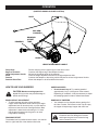
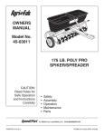
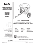
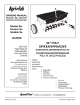
Operator's Manual
®
44" High Speed Sweeper
Model No. 486.24644
CAUTION:
Before using this product, read
this manual and follow all Safety
Rules and Operating Instructions.
STOP
DO NOT RETURN TO STORE
For Missing Parts or Assembly
Questions Call 1-866-576-8388
•
•
•
•
•
Safety
Assembly
Operation
Maintenance
Parts
Sears Brands Management Corporation, Hoffman Estates, IL 60179 U.S.A.
www.craftsman.com
PRINTED IN U.S.A.
FORM NO. 42889 (09/04/13)
TABLE OF CONTENTS
WARRANTY.....................................................................2
safety rules...............................................................3
carton contents......................................................3
hardware package...................................................4
ASSEMBLY.......................................................................5
operation...................................................................10
troubleshooting....................................................11
maintenance.............................................................11
storage......................................................................11
service and adjustments....................................12
NOTES...........................................................................13
REPAIR PARTS ILLUSTRATION....................................14
REPAIR PARTS LIST.....................................................15
parts ordering/service...................... back page
WARRANTY
CRAFTSMAN ONE YEAR FULL WARRANTY
For one year from the date of purchase, this product is warranted against any defects in material or workmanship.
A defective product will be replaced free of charge.
For warranty coverage details to obtain free replacement, visit the web site: www.craftsman.com
This warranty is void if this product is ever used while providing commercial services or if rented to another person.
This warranty gives you specific legal rights, and you may also have other rights which vary from state to state.
Sears Brands Management Corporation, Hoffman Estates, IL 60179
The model number and serial numbers will be found on a
decal attached to the 44" High Speed Sweeper.
MODEL NUMBER:
486.24644
You should record both the serial number and the date of
purchase and keep in a safe place for future reference.
SERIAL NUMBER:
__________________
DATE OF PURCHASE:
__________________
2
safety rules
Remember, any power equipment can cause injury if operated improperly or if the user does not understand how to
operate the equipment. Exercise caution at all times when using power equipment.
• Read the vehicle and sweeper owners manuals and know how to operate your vehicle and sweeper before using this
sweeper attachment. Always instruct other users before they operate the sweeper.
• Vehicle braking and stability may be affected with the addition of an accessory or an attachment. Be aware of
changing conditions on slopes.
• Do not permit children to operate sweeper.
• Do not permit anyone to ride on sweeper.
• Operate the sweeper at reduced speed on rough terrain, near ditches and on hillsides to prevent loss of control.
• Vehicle braking and stability may be affected with attachment of this sweeper. Do not fill sweeper to maximum capacity
without checking capability of the towing vehicle to safely pull and stop with the sweeper attached. Stay off of steep slopes
• Do not exceed 6 m.p.h. Driving too fast may cause damage to sweeper's wheels and bearings.
• Do not hold onto dump handle while tractor is moving.
• Never attach dump handle to tractor or any part of your body. Always keep it secured to the hopper bag while tractor is
moving. If any part of dump handle should become damaged, stop use of sweeper and replace the damaged part.
• Stop and inspect vehicle and sweeper for damage after striking an object. Repair any damage before continuing operation.
• Keep sweeper away from fire. Excessive heat can damage the brushes and hopper bag and could cause the bag and its
contents to burn.
• Before storing the sweeper, always empty the hopper bag to avoid spontaneous combustion.
• Follow maintenance and lubrication instructions as outlined in the maintenance section of this manual.
Look for this symbol to point out important safety precautions. It means — Attention! Become alert!
Your safety is involved.
carton contents
10
5
42020
9
42540
42649
11
7
4
27425
2
40897
3
6
8
42646
12
23014
24192
1
27421
27424
42539
3
41487
hardware package
SHOWN FULL SIZE
16
(x1)
15
(x5)
25
(x6)
23
(x4)
22
(x2)
20
(x2)
48366
23368
18
(x1)
48365
19
(x13)
21
(x5)
47810
59
(x2)
HA23636
44292
47623
43055
47605
43343
NOT SHOWN FULL SIZE
28
(x2)
27426
26
(x2)
60
(x1)
27
(x2)
26484
41036
23353
4
ASSEMBLY
TOOLS REQUIRED FOR ASSEMBLY
(2)
STEP 3: (SEE FIGURE 3)
1/2" Wrenches
•
Install a compression spring (27) into the bottom of
each of the pivot rod retainers, securing them to the
bag arm channels.
STEP 1: (SEE FIGURE 1)
•
Secure each bag arm channel (6) to the sweeper
housing using two 3/8" x 2-1/4" clevis pins (23) and
two small hairpin cotters (19).
23
6
19
27
figure 3
figure 1
STEP 4: (SEE FIGURE 4)
•
STEP 2: (SEE FIGURE 2)
•
Place a pivot rod support bracket (28) in the end of a
bag arm channel and then insert a pivot rod retainer
(26) down into the slots in the bracket and the
channel. Repeat for the other bag arm channel.
•
Attach the drawbar brackets (4) to the drawbar (3)
using one 5/16" x 2-1/2" hex bolt (15), two washers
(59), and one 5/16" nylock nut (21). Make the nut
finger tight only.
Insert the 3/8" x 3" pin (16) into the brackets and
drawbar and install a small hairpin cotter (19).
26
2
16
15
1
59
4
3
28
4
59
19
21
figure 4
figure 2
5
STEP 5: (SEE FIGURE 5)
•
STEP 7: (SEE FIGURE 7)
Attach the drawbar and brackets to the sweeper
using two 5/16" x 2-12" hex bolts (15) and two 5/16"
nylock nuts (21). Tighten all three bolts installed in the
brackets, then loosen the front bolt by 1/4 to 1/2 turn.
•
Install a rear hopper tube (9) onto the ends of the two
lower hopper tubes (7). Secure them with two 1/4 x
1.11" clevis pins (25) and small hairpin cotters (19).
9
7
19
15
25
21
7
figure 5
figure 7
STEP 6: (SEE FIGURE 6)
•
•
•
Measure the distance from the tractor hitch to
the ground. Arrange the hitch brackets as shown
according to your tractor's hitch height.
Attach the bent hitch bracket (2) and straight hitch
bracket (1) to the drawbar using two 5/16" x 2-1/2" hex
bolts (15) and 5/16" nylock nuts (21).
Assemble the hitch pin (60) and two 3/4" spacers
(22) to the hitch brackets. Secure them in place with a
large hairpin cotter (18).
STEP 8: (SEE FIGURE 8)
•
Install a rear hopper tube (9) onto the ends of the two
upper hopper tubes (8). Secure them with two 1/4 x
1.11" clevis pins (25) and small hairpin cotters (19).
9
15
8
holes point down
60
25
2
22
1
21
18
HITCH HEIGHT
9" TO 11"
19
8
HITCH HEIGHT
7" TO 9"
HITCH HEIGHT
11" TO 13"
figure 6
figure 8
6
STEP 9: (SEE FIGURE 9)
•
STEP 11: (SEE FIGURE 11)
Attach the upper and lower hopper tubes together
using two 3/8 x 1/2" clevis pins (20) and small hairpin
cotters (19).
•
Slide the bag frame tube (1) through the front flap of
the hopper bag.
holes point down
holes point up
20
19
1
figure 9
figure 11
STEP 12: (SEE FIGURE 12)
•
STEP 10: (SEE FIGURE 10)
•
Slide the hopper tubes into the hopper bag.
Insert the hopper support rods (11) into the holes of the
upper hopper tube. Then, flex and insert the rods into
the holes in the bottom rear hopper tubes.
11
figure 10
11
figure 12
7
STEP 13: (SEE FIGURE 13)
•
STEP 15: (SEE FIGURE 15)
Secure the bag frame tube to the lower hopper tubes
using two 1/4 x 1.11" clevis pins (25) and small
hairpin cotters (19).
•
Starting from the front of the bag, secure the hopper
bag to the bag frame using the velcro flaps.
3
2
1
19
25
figure 13
figure 15
STEP 14: (SEE FIGURE 14)
•
•
STEP 16: (SEE FIGURE 16)
Open up all the flaps on the hopper bag.
Snap the lower front flaps of the hopper bag to the
front of the hopper bag bottom.
•
Attach the rope (12) to the center of the upper rear
hopper tube.
12
figure 16
figure 14
8
STEP 17: (SEE FIGURE 17)
•
ATTACHING SWEEPER HITCH TO TRACTOR
Attach the hopper bag to the sweeper by sliding
the pivot bolts in the hopper tubes into the pivot rod
retainers in the ends of the bag arm channels.
1. Place the tractor and sweeper on a flat level surface.
2. Set the sweeper height adjustment to about the
middle of the adjustment range.
3. Attach the sweeper hitch to the tractor hitch, with the
hitch brackets arranged according to the drawbar
height of your tractor as shown in figure 19 below and
in figure 6 on page 6.
4. Arrange the spacers into one of the three possible
combinations as shown below in figure 19.
IMPORTANT: To obtain the best performance from your
sweeper, arrange the spacers so that the sweeper bag is
approximately level with the ground as shown in figure 18.
BRUSH HEIGHT ADJUSTED
APPROXIMATELY MID-WAY
figure 17
APPROXIMATELY LEVEL
(6" to 8" FROM SURFACE)
figure 18
GROUP "A" VEHICLES
WITH HITCHES
HAVING 11" TO 13"
GROUND CLEARANCE.
GROUP "B" VEHICLES
WITH HITCHES
HAVING 9" TO 11"
GROUND CLEARANCE.
GROUP "C" VEHICLES
WITH HITCHES
HAVING 7" TO 9"
GROUND CLEARANCE.
figure 19
9
operation
(sweeper shown in dump position)
ROPE
BAG ARM
CHANNELS
DRAWBAR
DRAWBAR
OFFSET
TUBE
KNOB
HEIGHT ADJUSTMENT HANDLE
Dump Rope
Bag Arm Channels
Height Adjustment Handle
Knob
Drawbar
Drawbar Offset Tube
Permits dumping of the hopper bag from the driver's seat.
Connects the hopper bag to the sweeper housing.
Adjusts the operating height of the sweeper.
Locks the height adjustment handle into a height adjustment hole.
Connects the sweeper to the towing vehicle. Adjusts for various height tractor hitches.
Allows the sweeper to be offset behind the tractor.
HOW TO USE YOUR SWEEPER
SWEEPING SPEED
• Do not exceed 6 m.p.h. Try a starting speed of
approximately 3 m.p.h. (third gear on most tractors).
Depending on conditions, it may be necessary to adjust
the sweeping speed in order to achieve best results.
CAUTION:Maximum towing speed is 6
m.p.h. Driving too fast may cause damage to
wheels and bearings.
BRUSH HEIGHT ADJUSTMENT
• To adjust sweeper brushes to best operating
height, loosen adjustment knob and lift up on height
adjustment lever to raise the brush, or push down on
the lever to lower the brush. See figure above. Best
adjustment is when the brush setting is 1/2" down
into the grass. Always mow the grass to an even
height before sweeping.
DUMPING OF SWEEPER
• Your sweeper can be dumped without getting off of
the rider or tractor. Pull forward on the rope to empty
the hopper. Always empty hopper after each use.
CAUTION: Keep sweeper away from fire.
Excessive heat can damage the brushes
and hopper bag and could cause the bag
and its contents to burn.
DRAWBAR OFFSET
The drawbar can be positioned at the center, or at the left
hand or right hand end of the drawbar offset tube.
10
maintenance
CUSTOMER RESPONSIBILITIES
Read and follow the maintenance schedule and the procedures listed in the maintenance section.
e
us se r
ge
ch ch u yea ar tora
a
ye e s
a
e e ea
for fter wice very efor
e
T
B
A
E
B
MAINTENANCE SCHEDULE
Fill in dates as you
complete regular service.
Service Dates
Check for loose fasteners X
Check for worn or damaged parts X X
Lubricate brush shaft bearings X
Lubricate wheel bearingsX
Clean SweeperXX
Clean, inspect and lubricate gears X
scheduled maintenance
Cleaning
•
•
•
•
Clean the sweeper after each use.
Inspect for worn or damaged parts, such as brushes
and wheels.
Every year, remove the wheels to clean and lubricate
the gears, wheels and axles. After cleaning, lubricate
the axles and the teeth on the gears and wheels with a
light coat of grease. To remove a wheel, pop off the hub
cap to expose the head of the bolt. Remove the nut and
step spacer from the bolt and then remove the wheel
along with the bolt and washers. When re-assembling,
be sure the step spacer is properly seated in the hole
in the sweeper housing. Refer to "Gear and Drive Pin
Service" and figure 21 on page 12.
•
•
Clean the sweeper housing with a soft brush or cloth.
Clean debris from the hopper bag with a brush or
broom.
Remove any material which has wrapped around the
brushes or the ends of the brush shaft.
troubleshooting
Wheels skid when sweeping
•
•
•
Brushes set too low.
Brushes are jammed.
Wheels are jammed.
•
•
•
Adjust height till brushes are 1/2" down into grass.
Stop sweeper. Remove obstruction.
Remove one wheel at a time to check for obstruction
or damage. Refer to Service and Adjustments section.
storage
•
CAUTION: Before storing the sweeper,
always empty hopper bag to avoid
spontaneous combustion.
•
•
•
Clean the sweeper and hopper bag thoroughly to
help prevent rust and mildew.
To collapse the hopper bag for storage, remove the
two hopper support rods from the rear of the hopper.
•
11
Remove the pin (16) from the center hole in the
drawbar brackets, fold the draw bar and then replace
the pin (16). Refer to figure 4 on page 5.
Remove the rear clevis pins (23) from the bag arm
channels and sweeper housing. Fold the bag arm
channels into the sweeper housing and replace the
clevis pins (23). Refer to figure 1 on page 5.
Store in a dry area.
service and adjustments
brush replacement
GEAR and DRIVE PIN Service
NOTE: Replace brushes one brush at a time.
1. Remove the hopper bag from the sweeper.
2. Loosen hex bolts and lock nuts on two single brush
retainers which clamp one brush to the double brush
retainers. DO NOT loosen or remove bolts which
fasten double brush retainers to brush shaft.
3. Slide the brush out of the retainers, noting on which
side of the brush the bristles overlap.
4. Install new brush, making sure the bristles overlap on
the same side of the brush as before.
IMPORTANT: Do Not remove both wheels at the same
time to avoid mixing of parts. (The pinion gears are not
interchangeable. The ratchet end of the gears is marked
"R" or "L".) Make notes on the position of all parts before
removing them.
• Remove the hub cap to expose the head of the bolt.
• Remove the bolt, washer, nut and step spacer.
• Remove the wheel and washer from the axle.
• To remove the larger 27 tooth gear, remove the
retaining ring and then remove the gear and washers.
• To remove the smaller pinion gear, remove the
retaining ring and then remove the gear, the drive
pin (located in the brush shaft), the washers and the
spacer. See figure 21.
• Clean all parts and replace worn parts.
• Lightly grease the shafts and the axle.
• Lightly grease the drive pin and the ratchet teeth
inside the pinion gear. Reassemble the drive pin,
pinion gear, the 27 tooth gear and the washers onto
the shafts. Lightly grease the teeth of both gears.
• Lightly grease the gear teeth on the wheel and then
reassemble the wheel, bolt and washers. Assemble
the step spacer and nut onto the bolt, fitting the small
end of the spacer into the sweeper housing. Tighten
the nut securely.
• Repeat on the other end of the sweeper.
• Check that the brushes rotate only during forward
motion of the sweeper. If the brushes are driven in
both forward and reverse, the drive pin is jamming.
If the brushes are driven only in reverse, the pinion
gears have been switched.
BRUSH ROTATION
OVERLAP
BRISTLES
DOUBLE
BRUSH
RETAINER
OVERLAP
BRISTLES
DO NOT
REMOVE
THIS BOLT
SINGLE
BRUSH
RETAINER (2)
figure 20
STEP SPACER
27 TOOTH GEAR
SPACER
DRIVE PIN
PINION GEAR
figure 21
12
NOTES
13
REPAIR PARTS
486.24644 44" High Speed Sweeper
To order replacement parts, call Sears Parts Direct 1-800-252-1698
or go to www.searspartsdirect.com
10
12
11
9
25
19
8
25
26
13
44
45
14
43 57
47
57
17
33
36 37 39
38
40
38
41
19
7
6
6
17
19
5
19
1
22
2
18
21
59
21
21
19
34
31
48
56
25
52 24
49
19
30
53
51
50
55 58
55
33
15
42
4
59
19
7
20
16
60
14
13
46
15
15
28
27
8
25
15
26
25
32
23
19
9
27
19
33 58
55
55
19
25
20
42
28
3
32
29
4
41
40
38
39
38
37
57
43
45 44
33
35
21
47
14
57
REPAIR PARTS
486.24644 44" High Speed Sweeper
To order replacement parts, call Sears Parts Direct 1-800-252-1698 or go to www.searspartsdirect.com
ref qty
1
1
2
1
3
1
4
2
5
1
6
2
7
2
8
2
9
2
10
1
11
2
12
1
13
2
14
2
15
5
16
1
17
2
18
1
19
13
20
2
21
5
22
2
23
4
24
8
25
6
26
2
27
2
28
2
29
1
30
1
31
1
part no
24192
23014
27421
27425
42020
27424
40897
42539
42649
42540
42646
41487
42210
712-3008
44292
47623
43432
43343
43055
48366
47810
23368
HA23636
47189
48365
26484
41036
27426
67634
67333
40891
description
Straight Hitch Bracket
Hitch Bracket
Drawbar
Drawbar Bracket
Bag Frame Tube
Bag Arm Channel
Lower Hopper Tube
Upper Hopper Tube
Rear Hopper Tube
Hopper Bag
Hopper Support Rod
Rope
Hex Nut, 3/8-16 Jam Nylock
Hex Nut, 3/8-16 Jam
Hex Bolt, 5/16-18 x 2-1/2"
Clevis Pin, 3/8" x 3"
Hex Bolt, 3/8-16" x 2-1/2"
Hairpin Cotter, 3/32" x 2-5/16"
Hairpin Cotter, 3/32" x 1.8"
Clevis Pin, 3/8-16" x 1/2"
Nylock Nut, 5/16-18
Spacer, .76" x 1" x .76"
Clevis Pin, 3/8" x 2-1/4"
Nylock Nut, 1/4"
Clevis Pin, 1/4" x 1.11"
Rod Retainer
Compression Spring
Pivot Rod Support Bracket
Sweeper Housing
Height Adjustment Tube
Height Adjustment Knob
ref qty part no
description
32
2
41570
Dust Cover
33
4
1650-1
Retaining Ring (E Type)
34
1
27257
44" Brush Shaft
35
1
48651
Gear, Pinion L.H.
36
1
48652
Gear, Pinion R.H.
37
2
47046
Dowel Pin, 1/4 x 3/4"
38
4 R19212016 Washer, .656" x 1.25" x .059"
39
2
23520
Spacer, .660" x 1.250" x .250"
40
2
44232
Ball Bearing
41
2
41437
Retainer, Bearing (Plastic)
42
2
44008
Washer, .78" x 1.125" x .025"
43
2
141
Washer, .378" x 1.25" x .061"
44
2
41017
Hub Cap
45
2
43932
Hex Bolt, 3/8-24 x 3-1/2"
46
2
1038
Nylock Jam Nut, 3/8-24
47
2
41948
Wheel
48
4
49954
Socket Screw, #10-32 x 1"
49
8
43012
Hex Bolt, 1/4-20 x 3/4"
50
4
46780
Sweeper Brush
51
4
23580
Brush Retainer (Double)
52
8
23581
Brush Retainer (Single)
53
4
47171
Nylock Nut, #10-32
54
4
C-9M5732 Pop Rivet (Not Shown)
55
4
44137
Washer, .518" x 1" x .02"
56
2
26538
Step Spacer, .41" x .75"
57
4
45088
Wheel Bearing
58
2
41434
Gear, 27 Tooth
59
2
47605
Washer, 411" x 1" x .03"
60
1
23353
Hitch Pin
1
42889
Owners Manual
15
To order replacement parts, call Sears Parts Direct 1-800-252-1698
or go to www.searspartsdirect.com