1
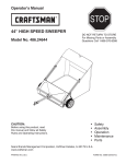
Owner's Manual
STOP
®
42" HIGH SPEED
LAWNSWEEPER
DO NOT RETURN TO STORE
For Missing Parts or Assembly
Questions Call 1-866-576-8388
Model No's. 486.24266
CAUTION:
Before using this product, read
this manual and follow all Safety
Rules and Operating Instructions.
Want more information
or assembly tips?
Scan for Video
Instruction Guide.
•
•
•
•
•
Safety
Assembly
Operation
Maintenance
Parts
Sears Brand Management Corporation, Hoffman Estates, IL 60179 U.S.A.
www.craftsman.com
PRINTED IN U.S.A.
FORM NO. 41750 (10/02/14)
TABLE OF CONTENTS
Safety Rules..................................................................... 1
Warranty........................................................................... 2
Accessories and Attachments.......................................... 3
Carton Contents............................................................... 3
Full Size Hardware Chart.................................................. 4
Sweeper Assembly Instructions........................................ 5
Hopper Assembly Instructions.......................................... 7
Operation........................................................................ 12
Maintenance Schedule................................................... 13
Storage........................................................................... 13
Service and Adjustments................................................ 14
Troubleshooting.............................................................. 14
Repair Parts Illustration.................................................. 15
Repair Parts List............................................................. 16
Parts Ordering................................................BACK PAGE
WARRANTY
CRAFTSMAN LIMITED WARRANTY
FOR ONE YEAR from the date of sale this product is warranted against defects in material or workmanship.
WITH PROOF OF SALE a defective product will be replaced free of charge.
For warranty coverage details to obtain free replacement, visit the web page: www. craftsman.com/ warranty
To obtain warranty coverage, return a defective product with proof of sale to the retailer from which it was purchased for free
replacement.
This warranty is void if this product is ever used while providing commercial services or if rented to another person.
This warranty gives you specific legal rights, and you may also have other rights which vary from state to state.
Sears Brands Management Corporation, Hoffman Estates, IL 60179
DO NOT RETURN TO STORE for Missing Parts or Assembly Questions
Call 1-866-576-8388 Attachment Hotline
SAFETY
Any power equipment can cause injury if operated improperly or if the user does not understand how to operate the equipment.
Exercise caution at all times, when using power equipment.
6. Vehicle braking and stability may be affected with
the attachment of this sweeper. Do not fill sweeper
to maximum capacity without checking the capability
of the towing vehicle to safely pull and stop with the
sweeper attached. Stay off of steep slopes.
7. Stop and inspect vehicle and sweeper for damage
after striking an object. Repair any damage before
continuing operation.
8. Keep sweeper away from fire. Excessive heat can
damage the brushes and hopper bag and could
cause the bag and its contents to burn.
9. Before storing the sweeper, always empty the hopper
bag to avoid spontaneous combustion.
10. Follow maintenance and lubrication instructions as
outlined in the maintenance section of this manual.
1. Read the vehicle and sweeper owners manuals and
know how to operate your vehicle and sweeper before
using this sweeper attachment. Always instruct other
users before they operate the sweeper.
2. Do not permit children to operate sweeper.
3. Do not permit anyone to ride on sweeper.
4. Never attach the hopper rope to any part of your body
or clothing! Never hold onto the rope while towing the
sweeper! Attach the rope to the towing vehicle to keep
it away from wheels and rotating parts.
5. Operate the sweeper at reduced speed on rough
terrain, near ditches and on hillsides to prevent loss
of control.
Look for this symbol to point out important safety precautions. It means — Attention!!
Become alert!! Your safety is involved.
The model and serial numbers will be found on a decal
attached to the lawnsweeper.
You should record both the serial number and the date of
purchase and keep in a safe place for future reference.
MODEL NUMBER:
SERIAL NUMBER:
DATE OF PURCHASE:
2
486.24266
____________________
____________________
ACCESSORIES AND ATTACHMENTS
These accessories were available when the unit was purchased. They are also available at most Sears retail
outlets and service centers. Most Sears stores can order repair parts for you when you provide the model
numbers of your tractor and sweeper
The Front Mount Dethatcher, Model 486.24219 attaches
to the lawn sweeper to help loosen and remove dead
grass and thatch from the lawn while sweeping.
CARTON CONTENTS
10
11
13
12
11
7
10
2
1
8
12
6
14
9
15
2
4
16
3
5
REF
PART NO.
QTY
1
–––
1
2
49766
2
3
46777
4
24192
5
DESCRIPTION
REF
PART NO.
QTY
Sweeper Housing Assembly
9
49768
1
Hopper Bag
Bag Arm Tube
10
47477
2
Rear Hopper Tube
Hitch Tube, L.H. (Left Hand)
11
49765
2
Upper Hopper Tube
1
Hitch Bracket
12
48726
2
Lower Hopper Tube
23687
1
Hitch Bracket, Bent
13
46823
1
Pivot Rod
6
46776
1
Hitch Tube, R.H. (Right Hand)
14
43938
2
Hopper Support Rod
7
–––
1
Brush Assembly (Right Hand)
15
24189
1
Bag Frame Strap
8
–––
1
Brush Assembly (Left Hand)
16
43737
1
Rope
3
DESCRIPTION
HARDWARE PACKAGE CONTENTS
SHOWN FULL SIZE
A
B
C
D
E
G
F
K
J
I
M
NOT SHOWN FULL SIZE
N
REF
PART NO.
QTY
A
46782
2
B
43224
C
O
DESCRIPTION
REF
PART NO.
QTY
Hex Bolt, 5/16-18 x 3" Lg.
I
23368
2
Hitch Spacer, 3/4"
2
Hex Bolt, 5/16-18 x 2-1/4" Lg.
J
46867
2
Clevis Pin, 1/4" x 1-3/4"
43084
4
Hex Bolt, 5/16-18 x 1-3/4" Lg.
K
48365
2
Clevis Pin, 1/4" x 1-1/8"
D
43661
4
Hex Bolt, 1/4-20 x 1"
L
48366
2
Clevis Pin, 3/8" x 1/2"
E
43978
4
Curved Head Bolt, 1/4-20 x 1"
M
43055
7
Hairpin Cotter, 3/32"
F
47189
8
Nylock Nut, 1/4"
N
23353
1
Hitch Pin
G
47810
8
Nylock Nut, 5/16"
O
44481
2
Vinyl Cap
H
44917
2
Palnut, 3/8"
4
DESCRIPTION
H
L
ASSEMBLY
TOOLS REQUIRED FOR ASSEMBLY
STEP 3: (SEE FIGURE 2)
•
(1)
(2)
(2) Tip the sweeper forward to access the brush shaft.
Hammer
7/16" Wrenches
1/2" Wrenches
STEP 1 - REMOVE PARTS FROM CARTON
•
•
•
To protect painted parts, lay them on cardboard or a
mat.
Remove the sweeper housing, the loose parts and
the hardware package from the carton. Lay out the
parts and hardware as shown on pages 3 and 4.
Place the sheet of cardboard from inside the carton
onto your work surface to prevent scratching the
sweeper.
STEP 2: (SEE FIGURE 1)
•
FIGURE 2
Each brush assembly has one brush retainer
marked with either red or black ink. Lay out the brush
assemblies as shown so that the brush retainers
marked with ink are in the middle with the black one
on your right and the red one on your left.
STEP 4: (SEE FIGURE 3)
IMPORTANT: Be sure the overlap bristles face out when
a brush is rotated to the bottom position.
•
BRUSH RETAINER
MARKED BLACK
BRUSH RETAINER
MARKED RED
Attach the brush assembly with the black brush
retainer to the right end of the brush shaft using two
hex bolts (D) and nylock nuts (F). The brush retainer
marked with black ink must be placed to the middle
of the sweeper.
NYLOCK NUT (F)
WELDED BRACE
OVERLAP BRISTLES
FIGURE 1
HEX BOLT (D)
BRUSH
RETAINER
MARKED
BLACK
OVERLAP
BRISTLES
5
FIGURE 3
STEP 5: (SEE FIGURE 4)
•
•
STEP 7: (SEE FIGURE 6)
Attach the brush assembly with the red brush retainer
to the left end of the brush shaft using two hex bolts
(D) and nylock nuts (F). The brush retainer marked
with red ink must be placed to the middle of the
sweeper.
Turn a wheel to rotate the brushes. (The wheels
drive the brushes in one direction only.) The overlap
bristles should be on the back side of the brush as it
rotates.
•
Hold the right hitch tube against the right side of the
sweeper so that the "76R" on the tube faces toward
the sweeper. Attach the hitch tube using two hex bolts
(C) and nylock nuts (G). Do not tighten yet.
HEX BOLT (C)
HEX BOLT (D)
NYLOCK NUT (G)
HOUSING
MARKED “R”
TUBE
MARKED
“76R”
BRUSH RETAINER
MARKED RED
NYLOCK NUT (F)
HITCH TUBE (R.H.)
FIGURE 6
FIGURE 4
STEP 6: (SEE FIGURES 5 AND 6)
•
•
The hitch tubes are stamped with a "77L" for the
left tube and a "76R" for the right tube. The sweeper
housing is marked with an "L" on the left with side
and an "R" on the right side.
Hold the left hitch tube against the left side of the
sweeper so that the "77L" on the tube faces away
from the sweeper. Attach the hitch tube using two hex
bolts (C) and nylock nuts (G). Do not tighten yet.
NYLOCK NUT (G)
STEP 8: (SEE FIGURE 7)
•
Fasten the hitch tubes together using two hex bolts
(A) and nylock nuts (G). Do not tighten yet.
HEX BOLT (A)
HEX BOLT (C)
HOUSING
MARKED “L”
NYLOCK NUT (G)
TUBE
MARKED
“77L”
FIGURE 7
HITCH TUBE (L.H.)
FIGURE 5
6
STEP 9
•
STEP 10b: (SEE FIGURE 9)
Use the mark along the side of this page to measure
the height of the tractor hitch. The mark is 10" from
the bottom of the page. If the tractor hitch is less than
10" above the ground, go to STEP 10a. If the tractor
hitch is 10" or more above the ground, go to STEP 10b.
•
•
If the tractor hitch is 10" or more above the ground,
assemble the hitch brackets as shown in figure 10. 10"
Insert two hex bolts (B) through the brackets, with
the rear hex bolt between the cross bolts in the hitch
tubes. Secure the hex bolts (B) with two nylock nuts
(G). Do not tighten yet.
Assemble the two spacers (I) onto the hitch pin (N)
and secure the pin with the hairpin cotter (M).
STEP 10a: (SEE FIGURE 8)
•
•
If the tractor hitch is less than 10" above the ground,
assemble the hitch brackets as shown in figure 9. Insert two hex bolts (B) through the brackets, with
the rear hex bolt between the cross bolts in the hitch
tubes. Secure the hex bolts (B) with two nylock nuts
(G). Do not tighten yet.
Assemble the two spacers (I) onto the hitch pin (N)
and secure the pin with the hairpin cotter (M).
HEX BOLTS (B)
HITCH PIN (N)
BENT HITCH
BRACKET
SPACERS (I)
HEX BOLTS (B)
HITCH
BRACKET
ASSEMBLY
HITCH PIN (N)
NYLOCK NUTS (G)
HITCH BRACKET
ASSEMBLY
HAIRPIN
COTTER (M)
FIGURE 9
SPACERS (I)
NYLOCK NUTS (G)
STEP 11
BENT HITCH
BRACKET
•
•
•
HAIRPIN COTTER (M)
FIGURE 8
7
Tighten the four bolts assembled in steps 6 and 7.
Tighten the two bolts assembled in step 9.
Tighten the two bolts assembled in step 10a or 10b.
ASSEMBLY OF HOPPER BAG
STEP 13: (SEE FIGURE 11)
•
STEP 12: (SEE FIGURE 10)
•
•
•
Fit the ends of the two upper hopper tubes into the
ends of a rear hopper tube. Align the holes in the
ends of the tubes and secure them in place using two
curved head bolts (E) and nylock nuts (F).
Fit the ends of the two lower hopper tubes into the
ends of a rear hopper tube. Align the holes in the
ends of the tubes and secure them in place using two
curved head bolts (E) and nylock nuts (F).
Unfold the hopper bag, reverse the fold of the mesh
wind screen and then lay the bag out flat with the
wind screen on top.
Insert the ends of the assembled upper hopper tubes
down through the stitched sleeves in the sides of the
hopper bag and then slide the tubes back underneath
the wind screen.
STITCHED SLEEVE
UPPER
HOPPER
TUBE
NOTE: Either side of the rear hopper tube can face up.
REAR
HOPPER
TUBE
CURVED HEAD
BOLT (E)
NYLOCK
NUT (F)
HOPPER
BAG
BOTTOM
UPPER
HOPPER
TUBE
FIGURE 11
STEP 14: (SEE FIGURE 12)
•
REAR
HOPPER
TUBE
NYLOCK
NUT (F)
•
Place the assembled lower hopper tubes into the
bottom of the hopper bag and then slide the tubes to
the back of the bag.
Attach the ends of the lower hopper tubes to the
inside of the upper hopper tubes using two clevis
pins (L) inserted from the inside, and two hair cotter
pins (M).
CURVED HEAD
BOLT (E)
UPPER HOPPER
TUBE
HAIR COTTER
PIN (M)
LOWER
HOPPER TUBE
FIGURE 10
LOWER HOPPER TUBE
CLEVIS PIN (L)
HOPPER BAG
BOTTOM
FIGURE 12
8
STEP 15: (SEE FIGURE 13)
•
STEP 17: (SEE FIGURE 15)
Insert the bag frame strap into the stitched sleeve at
the front edge of the bag bottom.
•
Fold the bag flaps around the lower hopper tubes and
attach to the bag bottom using the snaps.
BAG FRAME STRAP
STITCHED
SLEEVE
FLAP
SNAP
FIGURE 15
FIGURE 13
STEP 18: (FIGURE 16)
IMPORTANT: Do not over bend the support rods
during the following step. Over bending will cause the
steel rods to loose supporting tension.
STEP 16: (SEE FIGURE 14)
•
Assemble the bag frame strap to the holes in the
lower hopper tubes using two clevis pins (K) and hair
cotter pins (M).
•
BAG FRAME STRAP
Tip the hopper onto it's back to assemble the two
hopper support rods. Place the ends of each rod into
the upper and lower rear hopper tubes, bending the
rod just enough to fit into the holes in the tubes.
HAIR COTTER
PIN (M)
CLEVIS PIN (K)
SUPPORT
RODS
FIGURE 14
FIGURE 16
9
STEP 21: (SEE FIGURE 19)
STEP 19: (SEE FIGURE 17)
•
•
Slide the end of the pivot rod through the upper
hopper tube. Place a bag arm tube onto the rod. Slide
the rod through the stitched sleeve at the front edge
of the wind screen, and then place another bag arm
tube onto the rod. Slide the rod through the other
upper hopper tube.
Secure the rope to the center of the upper rear
hopper tube.
MOUNTING CLAMP
WIND SCREEN
HOPPER BAG
PIVOT ROD
FIGURE 19
BAG ARM TUBE
FIGURE 17
STEP 22: (SEE FIGURE 20)
•
STEP 20: (SEE FIGURE 18)
•
•
Assemble a vinyl cap (O) onto each bag arm tube.
Assemble two palnuts (H) onto the ends of the pivot
rod using a hammer.
To attach the hopper bag to the sweeper, slide the
ends of the bag arm tubes into the ends of the hitch
tubes and secure with two clevis pins (J) and hairpin
cotters (M).
BAG ARM TUBE
CLEVIS PIN (J)
HINT: To ease assembly of the palnuts, place the bag
on its side on a solid surface. With the bottom end of the
pivot rod against the surface, tap a palnut onto the top
end of the rod. Repeat for other end of rod.
HAIRPIN
COTTER (M)
CAP (O)
PALNUT (H)
MOUNTING CLAMP
FIGURE 20
FIGURE 18
10
ATTACHING SWEEPER HITCH TO TRACTOR
•
Place the tractor and sweeper on a flat level surface.
•
Set the sweeper height adjustment handle to about
the middle of its adjustment range.
•
Attach the sweeper hitch to the tractor hitch,
arranging the 3/4" spacers in one of six possible
combinations as shown in GROUP A and GROUP B
diagrams below.
BRUSH HEIGHT ADJUSTED
APPROXIMATELY MID-WAY
IMPORTANT: To obtain the best performance from your
sweeper, arrange the spacers so that the sweeper bag is
approximately level with the ground and approximately 5" to
7" off the ground as shown in figure 21.
APPROXIMATELY LEVEL
(5" to 7" FROM SURFACE)
FIGURE 21
GROUP "B" - For vehicles with hitches
having 10" to 13" ground clearance.
GROUP "A" - For vehicles with hitches
having 8" to 10" ground clearance.
HITCH BRACKET MOUNTED
ABOVE HITCH TUBES
HITCH BRACKET MOUNTED
BELOW HITCH TUBES
BLACK LINE IS TRACTOR HITCH
BLACK LINE IS TRACTOR HITCH
11
OPERATION
KNOW YOUR SWEEPER
HEIGHT
ADJUSTMENT
HANDLE
PIVOT ROD
WINDSCREEN
BAG ARM TUBE
HOPPER
ROPE
HITCH
BRACKETS
HOPPER BAG
Hopper Bag
Hopper Rope Windscreen
Bag Arm Tubes Pivot Rod
Height Adjustment Handle
Hitch Bracket Wing Knob
WING KNOB
Collects grass clippings, leaves and debris.
Permits dumping of hopper bag from driver's seat.
Helps prevent collected material from being blown out of hopper bag.
Connects the hopper bag to the sweeper housing.
Allows hopper bag to tilt forward to dump material.
Adjusts the operating height of the sweeper.
Connects the sweeper to the towing vehicle. Adjusts for various height tractor hitches.
Tightens the wheel in position after adjusting height.
CAUTION:Maximum towing speed is 6 m.p.h.
DUMPING OF SWEEPER
• Your sweeper can be dumped easily without getting
off of the rider or tractor. Simply pull the rope forward
to dump the hopper. Always empty hopper after each
use.
Driving too fast may damage wheels and bearings.
HOW TO USE YOUR SWEEPER
BRUSH HEIGHT ADJUSTMENT
• To adjust your sweeper brushes to the best operating
height, loosen the wing knob and push down on the
height adjustment handle to raise the brush, or push
up on the handle to lower the brush. Best adjustment
is when the brush setting is 1/2" down into the grass.
Always mow the grass to an even height before
sweeping.
SWEEPING SPEED
• Do not exceed 6 m.p.h. Try a starting speed of
approximately 3 m.p.h. (third gear on most tractors).
Depending on the conditions, it may be necessary to
adjust the sweeping speed in order to achieve best
results.
CAUTION: Never attach the hopper rope
to any part of your body or clothing! Never
hold onto the rope while towing the sweeper!
Attach the rope to the towing vehicle to keep
it away from wheels and rotating parts.
CAUTION: Keep sweeper away from fire.
Excessive heat can damage the brushes and
hopper bag and could cause the bag and its
contents to burn.
12
MAINTENANCE
CUSTOMER RESPONSIBILITIES
•
Read and follow the maintenance schedule and the
procedures listed in the maintenance section.
MAINTENANCE SCHEDULE
Fill in dates as you
complete regular service.
se e
ge
h u us ear r
ra
c
o
h
a
t
a
y
c
e
y es
a
e e ea
for ter wice very efor
T
Be Af
E
B
Check for loose fasteners
X
Check for worn or damaged parts X
Clean, inspect & lubricate wheel bearings Clean Sweeper
Clean, inspect & lubricate gears X
X
X
X
Service Dates
X
SCHEDULED MAINTENANCE
•
•
•
REMOVING LEFT SIDE WHEEL
Clean the sweeper after each use.
Inspect for worn or damaged parts, such as brushes
and wheels.
Every year, remove the wheels and clean the gear
teeth and the teeth on the back side of the wheel.
After cleaning, lubricate the axle, and the teeth on
the gears and the wheel with a light coat of grease.
To remove the right wheel, unscrew the wing knob
and remove the wheel and washers. To remove the
left wheel, pop off the hub cap using a screwdriver
and remove wheel along with the bolt, washers, step
spacer and nut. See figures 22 and 23.
NYLOCK
NUT
STEP
SPACER
WASHER
BOLT
WASHER
HUB
CAP
REMOVING RIGHT SIDE WHEEL
WING KNOB
WASHER
FIGURE 23
CLEANING
•
•
•
Clean sweeper housing with a soft brush or cloth.
Clean debris from hopper bag with a brush or broom.
Remove any material which has wrapped around
brushes or ends of brush shaft.
FIGURE 22
STORAGE
•
CAUTION:
Before storing the
sweeper, always empty the hopper bag to
avoid spontaneous combustion.
•
•
13
Clean the sweeper and hopper bag thoroughly to help
prevent rust and mildew.
To collapse the hopper bag for storage, remove the
two hopper support rods from the rear of the hopper.
Store in a dry area.
SERVICE AND ADJUSTMENTS
BRUSH REPLACEMENT
GEAR AND PAWL SERVICE
NOTE: Brush replacement should be done one brush at a time.
IMPORTANT: Do not remove both wheels at the same
time to avoid mixing of parts. (The R.H. and L.H. pinion
gears are not interchangeable.) Make notes on the
position of washers and snap rings during disassembly.
•
•
•
•
Remove the hopper bag from the sweeper.
Loosen the hex bolts and lock nuts on two single
brush retainers which clamp one brush to the double
brush retainers. Do Not loosen or remove the bolts
which fasten the double brush retainers to the brush
shaft. See figure 24.
Slide the brush out of the retainers, noting on which
side of the brush the bristles overlap. See figure 24.
Install new brush, making sure the bristles overlap on
the same side of the brush as before. See figure 24.
•
•
•
•
•
•
•
BRUSH ROTATION
BRUSH
SHAFT
OVERLAP
BRISTLES
•
•
SINGLE
BRUSH
RETAINERS
DOUBLE BRUSH RETAINER
Remove one wheel at a time, following the instructions
in the MAINTENANCE section.
Remove the retaining rings which hold the gears on the
brush shaft and the jack shaft.
Remove the pinion gear, washer and drive pin from the
end of the brush shaft. (The drive pin may fall out of the
brush shaft when the pinion gear is removed.)
Remove the idler gear and washers from the jack shaft.
Clean all parts.
Replace worn parts.
To reassemble, lightly grease the jack shaft and the
brush shaft. Insert the pin into the hole in the brush
shaft. Make sure the pin stays in the shaft.
Lightly grease the teeth on both gears and fill the
recess of the pinion gear with grease. Assemble both
gears back onto the shafts.
Lightly grease the axle and then reassemble the wheel
onto it. The brushes should rotate only during forward
rotation of the wheel. If the brushes are driven (rotated)
by both forward and reverse rotation of the wheel, the
drive pin is jamming in the pinion gear. Disassemble
and clean and lubricate the drive pin and pinion gear.
OVERLAP
BRISTLES
WASHER
WASHER
IDLER
GEAR
RETAINING
RING
BRUSH ROTATION
FIGURE 24
DRIVE
PIN
WASHER
PINION
GEAR
FIGURE 25
TROUBLESHOOTING
Wheels skid when sweeping.
• Brushes set too low.
•
• Brushes are jammed
• Wheels are jammed.
•
•
14
Adjust height till brushes are 1/2"
down into grass.
Stop sweeper. Remove obstruction.
Remove one wheel at a time to check
for obstruction or damage. Refer to
Service and Adjustments section.
NOTES
15
REPAIR PARTS
486.24266 42" HIGH SPEED LAWNSWEEPER
To order replacement parts, call Sears Parts Direct 1-800-252-1698 or go to www.searspartsdirect.com
60
50
17
55
51
52
53
58
61
57
54
49
17
52
51
46
56
55
46
50
57
48
54
11
59
49
12
1
46
56
19
46
48
37
38
39
40
17
13
14
36 34
13
16
7
35
47
30 31
29
25 26 26
22
23
10
28 27
27
41
33
33
43
32
47
46
20
20
7
21
6
8
41
3
16
45
33
33
41
44 33
46
5
33
19
18
41
2
15
22
46
42
4
33
REPAIR PARTS
486.24266 42" HIGH SPEED LAWNSWEEPER
To order replacement parts, call Sears Parts Direct 1-800-252-1698 or go to www.searspartsdirect.com
ITEM PART NO. QTY DESCRIPTION
ITEM PART NO. QTY DESCRIPTION
1
67105
1
Housing Assembly
32
43182
4
Bolt, Hex 5/16-18 x 3/4" Lg.
2
68202
1
Height Adjustment Tube Ass'y.
33
47810
12 Nut, Nylock 5/16-18 Thread
3
46776
1
Hitch Tube, R.H.
34
27234
1
Retainer, Carriage Bolt
4
46777
1
Hitch Tube, L.H.
35
42425
1
Bolt, Carriage 5/16-18 x 3-1/2"
5
24192
1
Bracket, Hitch (Straight)
36
43943
1
Grip, Height Adjust
6
23687
1
Bracket, Hitch
37
41017
1
Hub Cap
7
41436
2
Wheel & Tire Ass'y. (with bearings)
38
43932
1
Bolt, Hex 3/8-24 x 3-1/2" Lg.
8
41570
2
Dust Cover
39
26538
1
Spacer, Step
9
67103
1
Wheel Drive Assembly, L.H. (Not
40
1038
1
Nut, Nylock 3/8-24 Thread
Shown)
41
43084
4
Bolt, Hex 5/16-18 x 1-3/4" Lg.
10
67102
1
Wheel Drive Assembly, R.H.
42
46782
2
Bolt, Hex 5/16-18 x 3" Lg.
11
27235
1
Brush Shaft
43
43224
2
Bolt, Hex 5/16-18 x 2-1/4" Lg.
12
46780
4
Brush, 42"
44
23353
1
Pin, Hitch
13
23581
8
Retainer, Brush (Single)
45
23368
2
Tube, Hitch Spacer
14
23580
4
Retainer, Brush (Double)
46
43055
7
Hairpin Cotter, 3/32" #3
15
43661
4
Bolt, Hex 1/4-20 x 1" Lg.
47
46867
2
Pin, Clevis 1/4" x 1-1/2" Lg.
16
43012
8
Bolt, Hex 1/4-20 x 3/4" Lg.
48
48365
2
Pin, Clevis 1/4" x 1-1/8"
17
47189
16 Nut, Nylock 1/4-20 Thread
49
48366
2
Pin, Clevis 3/8" x 1/2"
18
43720
1
Wing Knob
50
43978
4
Curved Head Bolt, 1/4-20 x 1"
19
141
2
Washer, .378 x 1.25 x .061 51
44917
2
Palnut, 3/8"
20
45088
4
Wheel Bearing
52
44481
2
Cap, Vinyl
21
44008
2
Washer, 1-1/8" x .78" x .025"
53
46823
1
Pivot Rod, Hopper Bag
22
1650-1
4
Ring, Retaining (E-type)
54
49766
2
Tube, Bag Arm
23
48652
1
Gear, Pinion R.H.
55
47477
2
Tube, Rear Hopper Frame
24
48651
1
Gear, Pinion L.H. (not shown)
56
48726
2
Tube, Lower Hopper Frame
25
47046
2
Dowel Pin (Drive)
57
49765
2
Tube, Upper Hopper Frame
26 R19212016
4
Washer, .656 x 1.25 x .025
58
43938
2
Hopper Support Rod
27
44137
4
Washer, 1/2" x 1" x .02"
59
24189
1
Strap, Bag Frame
28
41434
2
Idler Gear, 27 T. 60
41751
1
Hopper Bag
29
23520
2
Spacer, .660 ID x .250 OD x .25
61
43737
1
Hopper Rope
30
44232
2
Ball Bearing
41750
1
Owners Manual
31
41437
2
Bearing Retainer
17
18
19
Product questions or problems?
1-888-331-4569
Customer Care Hot Line
Get answers to questions, troubleshoot problems,
order parts, or schedule repair service.
Para respuestas a preguntas o problemas, y ordenar
piezas o pedir servicio para la reparación de su equipo.
To help us help you, register your product at www.craftsman.com/registration
Para poderte ayudar mejor, registra tu producto en www.craftsman.com/registration
Join the Craftsman Club today!
Receive exclusive member benefits including special pricing and offers,
project sharing, expert advice, and SHOP YOUR WAY REWARDS!
Como miembro exclusivo, recibe diversos beneficios como ofertas, precios especiales, proyectos
nuevos, consejos de expertos y nuestro programa de puntos SHOP YOUR WAY REWARDS!
® Registered Trademark / TM Trademark of KCD IP, LLC in the United States, or Sears Brands, LLC in other countries
® Marca Registrada / TM Marca de Fábrica de KCD IP, LLC en Estados Unidos, o Sears Brands, LLC in otros países