1
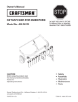
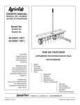
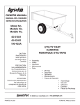
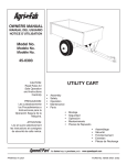
Owner's Manual
®
40" TINE DETHATCHER
Model No. 486.243152
Model No. 486.24316
CAUTION:
Before using this product, read
this manual and follow all Safety
Rules and Operating Instructions.
STOP
DO NOT RETURN TO STORE
For Missing Parts or Assembly
Questions Call 1-866-576-8388
•
•
•
•
•
Safety
Assembly
Operation
Maintenance
Parts
Sears, Roebuck and Co., Hoffman Estates, IL 60179 U.S.A.
www.sears.com/craftsman
PRINTED IN U.S.A.
FORM NO. 42107 (8/14/08)
TABLE OF CONTENTS
SAFETY RULES........................................................... 2
FULL SIZE HARDWARE CHART................................. 3
CARTON CONTENTS.................................................. 4
ASSEMBLY................................................................... 4
OPERATION................................................................. 6
MAINTENANCE/STORAGE......................................... 6
REPAIR PARTS .......................................................... 7
PARTS ORDERING/SERVICE.....................Back Cover
WARRANTY
ONE YEAR FULL WARRANTY
When operated and maintained according to the instructions supplied with it, if this Tine Dethatcher fails due to a defect in
material or workmanship within one year from the date of purchase, call 1-800-4-MY-HOME® to arrange for free repair (or
replacement if repair proves impossible).
If this product is used for commercial or rental purposes, this warranty applies for only 90 days from the date of purchase.
This warranty gives you specific legal rights, and you may also have other rights which vary from state to state.
Sears, Roebuck and Co., D817WA, Hoffman Estates, IL 60179
The model number and serial numbers will be found on a
decal attached to the dethatcher.
SERIAL NUMBER:
__________________
You should record both the serial number and the date of
purchase and keep in a safe place for future reference.
DATE OF PURCHASE:
__________________
SAFETY
Any power equipment can cause injury if operated improperly or if the user does not understand how to operate the equipment.
Exercise caution at all times when using power equipment.
• Read this owners manual carefully for operating and
service instructions before attempting to assemble or
operate this equipment. Be thoroughly familiar with
the proper use of this equipment.
• Read the vehicle owners manual and vehicle safety
rules, and know how to operate the vehicle before
using this equipment.
• Never allow children to operate the tractor or
dethatcher attachment, and do not allow adults to
operate without proper instructions.
• This dethatcher attachment has sharp tine points.
Always handle with care and wear substantial foot
wear when operating this dethatcher.
• Do not allow anyone to ride or sit on dethatcher
attachment frame or on towing vehicle.
• Keep the area of operation clear of all persons,
particularly small children, and also pets.
• Always begin with the transmission in first (low) gear
and engine at low speed, and gradually increase
speed as conditions permit.
• The vehicle braking and stability may be affected
with the attachment of this equipment. Be aware of
changing conditions on slopes. Refer to safety rules in
the vehicle owner's manual concerning safe operation
on slopes. STAY OFF OF STEEP SLOPES.
• Always operate up and down a slope, never across
the face of a slope
• This equipment should be operated at reduced speed
on rough terrain, along creeks and ditches and on
hillsides, to prevent tipping and loss of control. Do not
drive too close to a creek or a ditch.
• Do not tow this equipment on a highway or any other
public thoroughfare.
• Follow the maintenance instructions as outlined in this
owners manual.
Look for this symbol to point out important safety precautions. It means — Attention!!
Become alert!! Your safety is involved.
2
HARDWARE PACKAGE CONTENTS
SHOWN FULL SIZE
A
B
C
D
E
F
H
I
NOT SHOWN FULL SIZE
J
Ref.
Qty.
A
B
C
D
E
F
G
2
2
2
11
4
1
1
K
Description
Shoulder Bolt
Hex Bolt, 5/16" x 2" Lg.
Hex Bolt, 5/16" x 1-1/4" Lg.
Hex Bolt, 5/16" x 1" Lg.
Carriage Bolt, 5/16" x 1"
Hair Cotter Pin, 1/8"
Hitch Pin, 3/8"
3
Ref.
Qty.
H
I
J
K
19
2
4
1
Description
Nylock Nut, 5/16"
Nylock Nut, 3/8"
Angle Bracket
Grip
G
ASSEMBLY
CARTON CONTENTS
• Assemble two (tall) hitch arm mount brackets and two
(short) angle brackets to the bottom of the tine shield
at the rear. Use four 5/16" x 1" hex bolts and 5/16"
nylock nuts. Do not tighten yet. Position the brackets
as shown in figure 1.
• Assemble two angle brackets to the bottom of the tine
shield at the front. Use two 5/16" x 1" hex bolts and
5/16" nylock nuts. Do not tighten yet. Position the
brackets as shown in figure 1.
1
2
3
5
HITCH ARM
MOUNT BRACKET
6
ANGLE
BRACKET
5/16" NYLOCK
NUT
4
7
ANGLE
BRACKET
5/16" x 1"
HEX BOLT
FIGURE 1
1.
2.
3.
4.
5.
6.
7.
Hitch Mount Arms (2)
Lift Handle
Hitch Brackets (2)
Axle Bracket
Hitch Arm Mount Brackets (3)
Wheels (2)
Tine Shield Assembly
• Fasten the hitch mount arms to the outside of the front
angle brackets. Use two 5/16" x 1" hex bolts and 5/16"
nylock nuts. Tighten, then loosen the nuts slightly.
See figure 2.
• Fasten the hitch mount arms to the outside of the rear
hitch arm mount brackets. Use two 5/16" x 1" carriage
bolts and 5/16" nylock nuts. Do not tighten yet. See
figure 2.
TOOLS REQUIRED FOR ASSEMBLY
(2)1/2" wrenches
(1)9/16" wrench
(1)3/4" wrench or adjustable wrench
(1)Pliers
5/16" x 1"
CARRIAGE BOLT
5/16"
NYLOCK
NUT
REMOVAL OF PARTS FROM CARTON
• Remove all parts and hardware packages from the
carton. Lay out all parts and hardware and identify
using the illustrations on pages 3 and 4.
FIGURE 2
4
5/16"
NYLOCK
NUT
5/16" x 1"
HEX BOLT
• Assemble the front ends of the hitch mount arms
together using two 5/16" x 1-1/4" hex bolts and 5/16"
nylock nuts. Do not tighten yet. See figure 3.
• Assemble the hitch brackets to the top and bottom of
the hitch mount arms using two 5/16" x 2" hex bolts
and 5/16" nylock nuts. Do not tighten yet. See figure
3.
• Assemble the 3/8" hitch pin through the hitch brackets
and secure it with a 1/8" hair cotter pin. See figure 3.
• Assemble the wheels to the axle bracket using two
shoulder bolts and two 3/8" nylock nuts. Tighten. See
figure 5.
SHOULDER BOLT
3/8" NYLOCK NUT
5/16" NYLOCK NUT
1/8" HAIR
COTTER PIN
FIGURE 5
HITCH
BRACKET
5/16" x 1-1/4"
HEX BOLT
5/16" x 2"
HEX BOLT
• Assemble a hitch arm mount bracket to the axle
bracket using two 5/16" x 1" carriage bolts and 5/16"
nylock nuts. Do not tighten yet. See figure 6.
• Insert the lift handle down through the tine shield.
Attach it to the just assembled hitch arm mount
bracket using a 5/16" x 1" hex bolt and a 5/16" nylock
nut. Tighten. See figure 6.
• Position the hitch arm mount bracket so that there is
side tension on the lift handle when it is locked in the
up position. Tighten the nuts. See figure 6.
• Assemble the grip onto the end of the lift handle. See
figure 6.
3/8" HITCH PIN
FIGURE 3
• Tighten the bolts and nuts assembled in figure 3.
Tighten the bolts and nuts assembled in figure 1.
Tighten the rear bolts and nuts assembled in figure 2.
• Assemble the axle bracket to the outside of the rear
angle brackets using two 5/16" x 1" hex bolts and
5/16" nylock nuts. The angled ends of the axle bracket
must point as shown in figure 4. Tighten the bolts and
nuts and then loosen slightly.
GRIP
LIFT HANDLE
AXLE BRACKET
5/16" x 1"
CARRIAGE BOLT
5/16" x 1"
HEX BOLT
5/16" NYLOCK
NUT
5/16" NYLOCK NUT
5/16" x 1"
HEX BOLT
FIGURE 4
FIGURE 6
5
5/16"
NYLOCK
NUT
OPERATION
Regular removal of thatch is critical to maintenance of a
healthy lawn. Excessive thatch prevents air, water and
fertilizer from reaching the roots. To effectively dislodge
excessive thatch from your lawn, read these instructions
for proper adjustment and operation of the dethatcher.
OPERATING TIPS
• Vary the vehicle's forward speed until the best
dethatching action is achieved.
• For best results, use a crisscross pattern on your
lawn.
ADJUSTMENT OF TINE SHIELD
• Move the towing vehicle onto a level surface, such
as a driveway or garage floor and attach the tine
dethatcher to the vehicle hitch. See figure 7.
• Lower the dethatcher into operating position using the
lift handle. Loosen the two nylock nuts and carriage
bolts which fasten the hitch mount arms to the hitch
arm mount brackets at the rear of the tine shield.
Adjust the tine shield until it is level and both the front
and rear spring tines are in contact with the ground.
Retighten the hex nuts. See figure 7.
CARRIAGE BOLT
& NYLOCK NUT
• If the dethatcher appears to be "jumping" during
use, then extra weight should be added to the tine
shield. In most conditions extra weight will be needed.
Concrete patio blocks are recommended for weight
because of their low profile; however any type of
weight is suitable if it can be tied down to the shield.
Secure weight by using suitable binding material such
as rubber tie down straps or wire, fastening to the
holes in the shield flange. See figure 8.
HITCH
MOUNT
ARMS
FIGURE 8
FIGURE 7
MAINTENANCE/STORAGE
CUSTOMER RESPONSIBILITIES
• Read and follow the maintenance schedule and the maintenance procedures listed in this section.
MAINTENANCE SCHEDULE
Fill in dates as you
complete regular service.
e
us se on ge
ch ch u eas tora
a
s
e e ea y s e
for fter ver efor
e
E
B
A
B
Check for loose fasteners X
Lubrication •
•
•
•
Service Dates
X
Before each use check all nuts and bolts for tightness.
Lubricate wheels at least once a year or as needed.
If rust appears on the shield or spring tines, sand
lightly and coat with enamel paint.
Always store in a dry area, and coat exposed metal
with light oil when not in use.
• To remove a spring tine, insert a screw driver or
punch into the locking tab and pry up. Replace spring
tine and pry tab down. See figure 9.
SCREW
DRIVER
6
FIGURE 9
PARTS
40" TINE DETHATCHER MODELS 486.243152, 486.24316
15
8
15
15
6
15
4
16
3
18
4
10
16 12
12
15
16
15
9
1
1
16
5
13
19
7
16
12
15
12
5
16
16
7
16
14
2
16
DESCRIPTION
REF.
NO.
23442
23981
43783
47633
43021
24836
23914
24594
24595
24596
43029
23826
Hitch Arm Mount Bracket
Hitch Bracket
Spring Tine
Spring Alignment Wire
Wheel
Tine Shield
Hitch Mount Arm
Lift Plate
Axle Bracket
Lift Handle
Shoulder Bolt
Angle Bracket
13
14
15
16
17
18
19
20
21
* Purchase Common Hardware Locally
7
20
2
16
PART QTY.
NO.
3
2
10
2
2
1
2
1
1
1
2
4
1
16
11
13
11
REF.
NO.
1
2
3
4
5
6
7
8
9
10
11
12
17
17
PART QTY.
NO.
HA21362
43840
43063
47810
44326
43943
44180
47623
43343
42107
2
2
15
23
4
1
2
1
1
1
21
DESCRIPTION
Nylock Nut, 3/8-16
Hex Bolt, 5/16-18 x 1-1/4"
Hex Bolt, 5/16-18 x 1"
Nylock Nut, 5/16-18
Carriage Bolt, 5/16-18 x 1"
Handle Grip
Hex Bolt, 5/16-18 x 2"
Hitch Pin, 3/8" (Flat Head)
Hair Cotter Pin, 1/8"
Owner's Manual
Get it fixed, at your home or ours!
Your Home
For expert troubleshooting and home solutions advice:
www.managemyhome.com
For repair – in your home – of all major brand appliances,
lawn and garden equipment, or heating and cooling systems,
no matter who made it, no matter who sold it!
For the replacement parts, accessories and
owner’s manuals that you need to do-it-yourself.
For Sears professional installation of home appliances
and items like garage door openers and water heaters.
1-800-4-MY-HOME®
(1-800-469-4663)
Call anytime, day or night (U.S.A. and Canada)
www.sears.com
www.sears.ca
Our Home
For repair of carry-in items like vacuums, lawn equipment,
and electronics, call anytime for the location of your nearest
Sears Parts & Repair Service Center
1-800-488-1222 (U.S.A.)
www.sears.com
1-800-469-4663 (Canada)
www.sears.ca
To purchase a protection agreement on a product serviced by Sears:
1-800-827-6655 (U.S.A.)
1-800-361-6665 (Canada)
Para pedir servicio de reparación
a domicilio, y para ordenar piezas:
Au Canada pour service en français:
1-888-SU-HOGAR®
1-800-LE-FOYER MC
(1-888-784-6427)
® Registered Trademark / TM Trademark / SM Service Mark of Sears Brands, LLC
® Marca Registrada / TM Marca de Fábrica / SM Marca de Servicio de Sears Brands, LLC
MC
Marque de commerce / MD Marque déposée de Sears Brands, LLC
(1-800-533-6937)
www.sears.ca
© Sears Brands, LLC