1
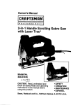
Operator's
Manual
®
55cc 2oCycie
GASOLINE
CHAIN
SAW
Model No. 316.350840
•
•
,
,
,
CAUTION:
Before using this
product,
read this manuaJ and
foJJow aJJ safety ruJes and operinstructions.
Sears,
Roebuck
and Co., Hoffman
Visit our website:
Estates,
SAFETY
ASSEMBLY
OPERATION
MAINTENANCE
PARTS LIST
[L 60179, U.S.A.
www.sears.com/craftsman
9096-31B204
date(J2/04)
Warranty
Page
2
Safety Rubs
Pages
3
OH and FueU Information
Page
Starting!Stopping
Instructions
Pages
15-21
TrouMeshooting
Page
22
9
Specifications
Page
23
Pages
1012
Repair Parts
Pages
24
Pages
13
Operation
ONE
YEAR
LIMITED
WARRANTY
Maintenance
8
and Repair
14
ON CRAFTSMAN
GAS
CHAIN
SAW
For one year from the date of purchase, when this Chain Saw is used and maintained according
operator's manual Sears will repair any defect in materia] or workmanship
free of charge.
This warranty excludes the bar, chain, spark pUug and air fluter, which are expendabb
wear out from norma] use in bss than two years.
If this Chain Saw is used for commercial
from the date of purchase.
or rental purposes,
this warranty
applies
to the
parts that can
for only 30 days
WARRANTY
SERVICE IS AVAILABLE
BY RETURNING
THiS CHAIN SAW TO THE NEAREST
SEARS STORE OR SEARS PARTS & SERVICE CENTER iN THE UNITED STATES.
This warranty
to state.
gives you specific
Sears, Roebuck
CALIFORNIA
legal rights, and you may also have other rights which vary from state
and Co., Dept. 817WA,
PROPOSITION
Hoffman
65 WARNING
Estates,
IL 60179
SPARK
ARRESTOR
NOTE
NOTE: For users on U.S° Forest Land and in the
states
THE ENGINE EXHAUST FROM THiS
PRODUCT CONTAINS CHEMICALS
KNOWN TO THE STATE OF CALIFORNIA
TO CAUSE CANCER, BIRTH
OR OTHER REPRODUCTIVE
DEFECTS
HARM.
of California,
Maine,
Oregon
and Washington,
All U.S. Forest Land and the state of California (Public
Resources Codes 4442 and 4443), Oregon and
Washington require, by law that certain internal combustion engines operated on forest brush and/or grass-covered areas be equipped with a spark arrestor, maintained in effective working order, or the engine be constructed, equipped and maintained for the prevention of
fire. Check with your state or local authorities for regulations pertaining to these requirements. Failure to follow
these requirements could subject you to liability or a
fine. This unit is factory equipped with a spark
arrestor. If it requires replacement, ask a Sears or other
qualified service dealer to install the Spark Arrestor Kit.
The purpose of safetysymbols isto attract
your attentionto possibledangers,The safetysymbols,and their
explanations,
deserveyour careful
attention
and understanding,
The safetywarningsdo notby themselves
eliminate
any danger,The instructions
or warningsthey
givearenotsubstitutes
forproperaccidentprevention
measures.
SYMBOL
SYMBOL
MEANING
MEANmNG
inJury,
NOTE: Advises you of information or instructions vital to
the operation or maintenance of the equipment.
Read the Operator's Manual(s) and follow aii warnings
and safety instructions,
Failure to do so can result in serious injury to the operator and/or bystanders,
,, IMPORTANT
SAFETY mNSTRUCTmONS ,,
READ ALL INSTRUCTIONS
PLAN AHEAD
WARNmNG: If0orrec.y
used,
the
chain saw usa
)[easant and safe work,always strictly cornwith the safety rules that are contained in
manual.
• Read the instructions carefully. Be familiar with the controis and proper use of the unit.
Do not operate tMs unit when tked, ill or under the influence of alcohol, drugs or medication.
Children must not operate the unit. Teens must be
accompanied and guided by an adult.
° Carry the chain saw with the engine stopped, the guide
bar and saw chain to the rear, and the muffler away
from your body,
When transporting your chain saw, use the appropriate
guide-bar scabbard (sheath).
• Wear protective gear. Always use steel-toed safety
footwear with non-slip soles; snug-fitting clothing;
heavy-duty non-slip gloves; eye protection such as
non-fogging, vented goggles or face screen; an
approved safety hard hat; and hearing protection.
Regular users should have hearing checked regularly as
chain saw noise can damage hearing.
OPERATE
YOUR
SAW SAFELY
• Do not operate a chain saw that is damaged, not calibrated properly or not fully assembled. Always replace
chain, bar, chain brake, and other parts immediately if
damage occurs.
• Only responsible individuals who are familiar with the
instructions may operate the chain saw (no one under
the age of 16). Provide parental supervision at all times.
Do not apply excess force to the chain saw at the end
of the cut. You may lose control of the unit when the cut
has been completed.
° Secure hair above shoulder length. Do not wear loose
clothing orjeweky; they can get caught in moving parts.
Keep all parts of your body away from the chain when
the engine is running,
Inspect the unit before use. Replace all damaged parts
prior to starting. Make sure the unit is in original operating condition before starting.
• Never start or run the unit inside a closed room or
building, Operate this unit only in a well ventilated outdoor area.
Know the controls and know how to stop the chain saw
quickly.
Use the unit only in daylight or good artificial light.
° Avoidacddentaistarting,Beinthe startingposition
whenever
pullingthe starterrope,Theoperatorandunit
mustbein a staMepositionwhib starting.See
Starting/Stopping
Instructions,
° Beforeyoustarttheengine,makesurethe areaaround
thesawis dear,Nevertryto startthe sawwhenthe
guidebaris engagedina cut.
Donotstartcuttinguntiiyouhavea clearworkarea,
securefooting,anda piannedretreatpathfromthe
fallingtree.
• Donotoperatea chainsawthatis damaged,
improperly
adjusted,or not completely
andsecurelyassembled,Be
surethatthesaw'schainstopsmovingwhenthethrottle
controltriggeris released.
° Shutoff theenginebeforesettingthechainsawdown,
° Useextremecautionwhencuttingsmall-sizedbrush
andsaplingsbecauseslendermaterialmaycatchthe
chainsawandwhiptowardsyouor causeyouto lose
control,
• Whencuttinga limbthatis undertension,bealertfor
springbacksothatyouwillnot bestruckwhenthe tensionin thewoodfibersis released,
Donotcutthroughnails,rodsinthe tree,railroadtiesor
pallets,Inspecta treethatyouaregoingto cutforforeignobjectsthatcouldcauseinjuryor damageto your
chainsaw,
Afterstrikinga foreignobject,stoptheengineandthoroughlyinspectfordamage,Repairas necessary,
Keepthehandlesdry,cleanandfreeof theoil/fuelmixture,
° Wedonot recommend
usingthechainsawin a treeor
ona ladder,
MAiNTAiNYOUR SAW iN GOOD WORKING ORDER
° When a chain saw is being used, a fire extinguisher
should be available.
° Always move at bast 10 feet (3 meters) from fueling site
before starting saw,
When re-fueling, turn the engine off and allow the saw to
cool in a non-combustible area, do not place on dry
leaves, straw, paper, etc, Slowly remove fuel cap and
refuel unit.
• Always store the unit and fuel in a cool, dry, well-ventilated space where fuel vapors cannot reach sparks or
open flames from water heaters, electric motors or
switches, furnaces, etc,
All chain saw service, other that the items listed in this
instruction manual maintenance instructions, should be
performed by a Sears or other qualified service dealer.
Use the right tool. Only use this chain saw for its intended purpose, to cut wood.
Never touch the chain or attempt to service the saw
while the engine is running. Make sure all moving parts
have stopped. Allow the chain saw to cool, as the chain
can be hot.
° Check the bar and chain at frequent intervals for proper
adjustment, Make sure the bar and chain are properly
tightened and sharpened, Visually inspect for damage.
Repair any damage before restarting or operating the
chain saw,
WARNING:
KICKBACK
occur when may
the
nose or tipofthe guide bar touches an
_ct,or when the wood closesinand
the saw chain inthe cut, Tipconact insome cases may cause a lightningfastreversereaction,
kinkingthe guide bar
• All chain saw service, other than the items listed in this
instruction manual maintenance instructions, should be
performed by a Sears or other qualified service dealer.
Make sure aii fasteners are in place and secure.
Unauthorized replacement parts or the removal of safety
devices may cause damage to the unit and possible
injury to the operator or bystanders, Use only Craftsman
accessories and replacement parts as recommended.
Never modify your saw,
When not in use, saw should be stored in a dry, highly
secure location away from children.
• When storing saw use a scabbard or carrying case.
HANDLE FUEL WiTH CAUTION
° Do not smoke while handling fuel or while operating the
saw.
Always eliminate all sources of sparks or flame in areas
where fuel is mixed or poured.
Always mix and pour fuel in an outdoor area and use an
approved, marked container for aii fuels. Always wipe
up all fuel spills before starting saw.
KICKBACK
SAFETY
PRECAUTIONS
• With a basic understanding of kickback, you can reduce
or eliminate the element of surprise. Sudden surprise
contributes to accidents. Be alert to the potential for
kickback at all times.
° Keep a good firm grip on the saw with both hands, the
right hand on the rear handle and the left hand on the
front handle, when the engine is running. Use a firm grip
with thumbs and fingers encircling the chain saw handles,
A firm grip will help you reduce kickback and maintain
control of the saw, Don't let go,
• Makesurethattheareain whichyouarecuttingisfree
fromobstructions.
Donot bt thenoseof theguidebar
contacta Hog,branch,fence,or anyotherobstruction
thatcouidbehit whib youareoperatingthesaw.
• Alwayscutwiththeenginerunningatfullspeed.FuHy
squeezethethrottbtriggerandmaintaina steadycutting speed.
• Useonlythecorrectoriginalequipmentmanufacturer
replacement
bars,chainsandotherpartsandaccessories.Theseareavailablefroma Searsor otherqualifiedservicedealer.Useof anyunauthorized
partsor
accessories
couldleadto seriousinjurytothe user,or
damageto theunit,andwiii voidyourwarranty.
• Followthemanufacturer's
sharpening
andmaintenance
instructions
forthe sawchain.
Useonlythereplacement
guidebarsandlowkickback
chainsspecifiedforyoursawto avoidinjury.
• Watchforshiftinglogsor otherforcesthatcouldpinch
or fall intochain.
Alwayshavesawat fullspeedwhenenteringa previous
cut.Alwaysusecautionwhenenteringa previouscut.
• Donot starta cutusingthetip of thesaw.
OTHER
SAFETY
PRECAUTIONS
Do not operate a chain saw with one hand! Serious
injury to the operator, helpers, bystanders, or any combination of these persons may result from one-handed
operation. A chain saw is intended for two-handed use.
• Do not operate a chain saw if you are fatigued.
• Use safety footwear; snug-fitting clothing; protective
gloves; and eye, hearing, and head protection devices.
Do not allow other persons to be near the chain saw
when starting or cutting with the chain saw. Keep
bystanders and animals out of the work area.
• Do not remove, damage or de-activate any of the safety
devices. Never use a damaged, modified, or improperly
repaired or assembled chain saw, Check their proper
operation regularly, Only use bars and chains of the
length indicated in the table herein.
Never carry out operations or repairs on your own that
are other than routine maintenance as listed in this
manual.
• Use caution when feiiing a tree. Make sure you have
planned an escape path when felling, and keep aii
bystanders away.
Be alert; stop the machine if anyone enters the cutting
area, which is usually 3 to 4 feet around the operator.
• Use caution when working in a crew to avoid injury to a
fellow worker who may enter the cutting area.
Only loan your saw to experienced users who are completely familiar with saw operation and correct use. Give
other users this manual, which they should read before
using the saw.
• Shut off the engine before setting down the saw. Do not
leave the engine running unattended.
Never store the unit, with fuel in the tank, inside a building where fumes may' reach an open flame or spark.
• Allow the engine to cool before storing or transporting
the chain saw over long distances. For example, let the
engine cool before placing the chain saw in an automobile. Also, be sure to secure the unit while transporting.
• Store the unit in a dry area, locked up, located up high
and located out of the reach of children to prevent
unauthorized use or damage.
Never douse or squirt the unit with water or any other
liquid. Keep handles dry, clean and free from debris.
Clean after each use.
• Keep these instructions. Refer to them often and use
them to instruct other users. If you loan someone this
unit, also loan them the instructions.
• Do not use the unit in the rain, in a storm or in inclement
weather.
FUEL SAFETY
Store fuel only in containers specifically designed and
approved for the storage of such materials.
• Always stop the engine and allow it to cool before
filling the fuel tank. Never remove the cap of the fuel
tank, or add fuel, when the engine is hot. Never operate
the unit without the fuel cap securely in place. Loosen
the fuei tank cap siowiy to relieve any pressure in the
tank.
• Add fuel in a clean, well-ventilated outdoor area where
there are no sparks or flames. Slowly remove the fuel
cap only after stopping engine. Do not smoke while fueling or mixing fuel. Wipe up any spilled fuel from the unit
immediately.
l_lAD_l|_l_o
Gasoline is highly
flammable, and its
vapors can explode if ignite& Take the following precautions:
_#=!
J '_ J 'Y m J 'Y %,,,,J•
• Avoid creating a source of ignition for spilled fuel. Do
not start the engine until fuel vapors dissipate.
Move the unit at bast 30 feet (9.1 m) from the fueling
source and site before starting the engine. Do not
smoke. Keep sparks and open flames away from the
area while adding fuel or operating the unit.
SAVE THESE JNSTRUC-
SAFETY
AND
_NTERNAT_ONAL
SYMBOLS
This operator's manual describes safety and international symbols and pictographs that may appear on this product.
Read the operator's manual for complete safety, assembly, operating and maintenance and repair information.
SYMBOL
SYMBOL
MEANING
• SAFETY
ALERT SYMBOL
Indicates danger, warning, or caution.
May be used in conjunction with other
symbols or pictographs.
MEANING
• ON/OFF CONTROL
ON / START / RUN
• ON/OFF CONTROL
OFF OR STOP
READ OPERATOR'S MANUAL
WARNING:
Read the
Operator's Manual(s) and follow all
warnings and safety instructions.
Failure to do so can result in serious
injury to the operator and/or
bystanders.
• WEAR EYE, HEARING AND
HARDHAT PROTECTION
WARNING:
WARNING:
Contact ofthe
guide bar tip with any object should
be avoided. Tip contact may cause
the guide bar to move suddenly
upward and backward, which may
cause serious injury.
Thrownobjects
and loud noisecan cause severeeye
injury
and hearingloss.Wear eye protectionmeeting
ANSI
Z87.1-1989 standardsand ear protectionwhen operatingthisunit.
Wear a hard hat.Use a full
faceshieJd
when needed.
• UNLEADED
GUIDE BAR
• USE BOTH HANDS
Always use both hands while operating the chain saw. Never use only one
hand to operate the saw.
FUEL
Aiwaysuseciean,ffeshunieadedfuei.
• RED CHOKE LEVER POSiTiONS
1 o FULL Choke Position
• OIL
Refer to operator's
proper type of oil.
manual for the
2 _ PARTIAL Choke Position
3 o RUN Position
7
17
22
23
13
14
15
10
11
15
CHAroN SAW COMPONENTS
SAFETY
1.
2.
GUIDE BAR
SAW CHAIN
2.
3.
4.
5.
SAW CHAIN ADJUSTMENT SCREW
SPARK ARRESTER SCREEN
CHAIN BRAKE' LEVER/HAND GUARD
3.
6.
7.
8.
FRONT HANDLE
STARTER HANDLE
SPARK PLUG
9.
10.
11.
12.
AIR CLEANER COVER
STOP SWITCH
SAFETY TRIGGER
BAR OIL RESEVOIR CAP
FEATURES
LOW KICKBACK SAW CHAIN heirs siqnificantly
reduce kickback, or the intensity of kicRback, due to
spedally designed depth gauges and guard links.
CHAIN SAW ADJUSTMENT SCREW It is normal for a
new chain saw chain to stretch after the first 30 minutes of use. Check the tension of the chain
reguhrly to ensure the best performance, see SAW
CHAIN ADJUSTMENT under MAINTENANCE AND
REPAIR INSTRUCTIONS.
13. STARTER COVER
14. FUEL TANK CAP
15. REAR HANDLE / BOOT LOOP
10. STOP SWITCH immediately stops the engine when
pushed up. Stop s?vitch must be pushed down to
start or restart engune.
16. THROTTLE LATCH
17. RED CHOKE LEVER
18. BAR RETAINING NUTS
11. SAFETY TRIGGER prevents acddentd acceleration
of the engine. Throttle trigger (19) cannot be
squeezedunless the safety trigger is depressed.
19. THROTTLE / TRIGGER
20. CHAIN CATCHER
21. CHAIN BRAKE r COVER
22. MULTI-PURPOSE TOOL
23. CARRY CASE
17. RED CHOKE LEVER aids in starting the engine.
19. THROTTLE TRIGGER controls engine speed.
20. CHAIN CATCHER reduces the danger of injury in
the event saw chain breaks or derauls during oper
ation. The chain catcher is designed to intercept a
KICKBACKSPECiFiCS
WARNING:
K_CKBACK
K okbaokoan
head
to
dangerous ioss of
control of the chain saw and result in serious
Pinch
SPECiFiCS
Kickback
Pinch kickback can occur when the saw chain is pinched
aiong the bottom or top of the guide bar.
When pinched on the bottom of the guide bar, it may puii
the saw forward, away from the operator
cause of most accidents.
KICKBACK may occur when the NOSE or TIP of the
guide bar touches an object, or when wood doses in and
pinches the saw chain in the cut.
Tip contact in some cases may cause a lightning-fast
reverse reaction, kicking the guide bar up and back
toward the operator.
Any of these reactions may cause you to lose control of
the saw, which could result in serious personal injury.
Rotationa_
When pinched aiong he top of the guide bar, it may push
the guide bar rapidiy back toward the operator.
--m-
A : Puii
B = Solid objects
Kickback
Rotational Kickback can occur when the moving
chain contacts an object at the upper tip of the guide
bar. This contact can cause the chain to dig into the
object, which stops the chain for an instant. The
result is a lightning fast, reverse reaction which kicks
the guide bar up and back toward the operator.
A
A
A = Kickback path
B = Kickback reaction zone
F_g. 1
A
--_B"
B
F_g.2
OraLAND FUEL MmXmNG mNSTRUCTmONS
To Obtain
OHdand/or impropeHy mixed fueHare the main reasons for
the unit not running property. Be sure to use fresh (Hess
than 60 days rid) dean unHeaded fuel Follow the instructions carefully for the proper fueHioiHmixture.
Thoroughly mix the proper ratio of 2-cycle engine oil with
unleaded gasoline in a separate fuel can. Use a 40:1
fuel/oil ratio. Do not mix them directly in the engine fuel
tank. See the table below for specific gas and oil mixing
ratios.
Definition
of Blended
Fuels
Today's fueHsare often a Mend of gasoHine and oxygenates such as ethanol methanol or MTBE (ether).
AHcohoH-bHendedfueHabsorbs water. As HittHeas 1% water
in the fueHcan make fueHand oH separate and Headto formation of acids during storage. When using aHcohoHMended fuel use fresh fuel
Using
Blended
Correct
Fuel Mix:
NOTE: One gallon (3.8 liters) of unleaded gasoline mixed
with one 3.2 oz. (95 ml.) bottle of
2-cycle oil makes a 40:1 fuel/oil ratio.
+
Fuels
If you choose to use a Mended fuel or its use is unavoidable, follow recommended precautions:
• Always use the fresh fuel mix explained in your operator's manual
• Always shake the fuel mix before fueling the unit
• Drain the tank and run the engine dry before storing the
unit
Using Fuel Additives
The bottle of 2-cycle oil that came with your unit contains
a fuel additive which will help inhibit corrosion and minimize the formation of gum deposits. It is recommended
that you use our 2-cycle oil with this unit.
UNLEADED GAS
2 CYCLE OIL
1 GALLON US
(3.8 UTERS)
3.2 FL OZ.
1 LITER
25 mm
MiXiNG
(95rnm)
RATIO - 40:1
If unavailable, use a good 2-cycle oil designed for
air-cooled engines along with a fuel additive, such as
STA-BIL _ Gas Stabilizer or an equivalent. Add 0.8 oz.
(23 ml.) of fuel additive per gallon of fuel according to the
instructions on the container. NEVER add fuel additives
directly to the unit's fuel tank.
I I^D IM N .
•
Add
foe,
ioao,eao,
well ventilated out-
vapors dissipate.
NOTE: Dispose of the old fuel/oil mix in accordance to
Federal, State and Local regulations.
IMPORTANT:
Operate
thisunitonly
Experience indicates that alcohol blended with fuels
(called gasohol or using ethanol or methanol) can
attract moisture which leads to separation and formation of acids during storage. Acidic gas can damage
the fuel system of an engine when in storage. To avoid
engine problems, the fuel system should be emptied
before storage for 30 days or longer. Drain the gas
tank, start the engine and let it run until fuel lines and
carburetor are empty. Use fresh fuel next season.
Never use engine or carburetor cleaner products in the
fuel tank or permanent damage can occur. See STORAGE instructions for additional information.
WARNING:
0naweDventHated
outdoor area. Carbon
monoxide exhaust fumes can be UethaU
in a
confined area.
WAR
N _ N G:
instaUUed.
BEFORE
STARTING
Never operate the saw
without the bar and
chain properUy
ENGINE
WARNING: Be sure to read the Oil and Fuel Information
.Section of this manuaH before you begin. If you do not
understand the oH and fueHinformation, do not attempt
to fueHyour unit. For more information contact your
HocaHSears service center at
1-800-4-MYHOMEC¢.
CHAIN
Be sure the chain brake is disengaged by pulling the
front hand guard back toward the front handle as far
as possible. The chain brake must be disengaged
before cutting with the saw.
WARNING: The chain brake must not move when the
engine runs at idle speed. If the chain brake moves at
idle speed, refer to CARBURETOR ADJUSTMENT in
this manual. Avoid contact with the muffler. A hot muffler can cause serious burns.
GUIDE BAR AND CHAIN OIL
The bar and chain require Hubrication. The chain oiler
provides continuous lubrication to the chain and guide
bar. Be sure to fill the bar oil tank when you fill the fuel
tank. (Capacity = 6.8 ft. oz.). Lack of oil will quickly
ruin the bar and chain. Too little oil will cause overheating with smoke coming from the chain and discoloration of the bar. For maximum guide bar and chain
life, we recommend you use Craftsman chain saw bar
oil. If Craftsman bar oil is not available, you may use a
good grade SAE 30 oil until you are able to obtain the
Craftsman brand. The oil output is automatically
metered during operation. Your saw will use approximately one tank of bar oil for every tank of fuel mix.
Always fill the bar oil tank when you fill the fuel tank.
FUEUNG
THE ENGINE
WARNING:
BRAKE
iMPORTANT
POINTS TO REMEMBER
When pulling the starter rope, do not use the full
extent of the rope as this can cause the rope to break.
Do not let starter rope snap back. Hold the handle and
let the rope rewind slowly. For cold weather starting,
start the unit at FULL CHOKE; allow the engine to
warm up before squeezing the throttle trigger.
DO NOT attempt to cut material with the choke/fast idle
lever in the FULL CHOKE position.
Remove fuel cap slowly when refueling.
This engine is certified to operate on unleaded gasoline. Before operation, gasoline must be mixed with a
good quality synthetic 2-cycle air-cooled engine oil.
We recommend Craftsman brand synthetic oil. Mix
gasoline and oil at a ratio of 40:1.40:1 ratio is
obtained by mixing 3.2 ounces of oil with 1 gallon of
unleaded gasoline. Included with this saw is a 3.2
ounce container of oil. Pour the entire contents of this
container into one gallon of gasoline to achieve the
proper fuel mixture. DO NOT use automotive oil or
boat oil. These oils will cause engine damage. When
mixing fuel, follow the instructions printed on the oil
container. Once oil is added to the gasoline, shake
container momentarily to assure that the fuel is thoroughly mixed. Always read and follow the safety rules
relating to fuel before fueling your unit.
10
STOPPmNG
mNSTRUCTmONS
1.
Release the trigger and allow the engine to return to
the idle speed.
2.
Move the STOP switch up to the STOP position (Fig.
4).
F
E
NOTE: For emergency stopping, push the Never of the
chain brake lever/hand guard (C) forward and
move the STOP switch up (Fig. 3, 4).
STARTmNG
A COLD
ENGmNE
To be sure to add the correctly mixed fuel to the fuel tank
(A) and to add bar and chain oil to the oil tank (B). Make
sure the chain brake is disengaged (C) before starting the
unit.
F_g.3
1. Slide the STOP switch down (Fig. 4). The red choke
meyer (H) has 3 positions: Positions 1, 2 and 3 (Fig. 6).
2.
Fully press and release the primer bulb (G) 10 times,
slowly. Some amount of fuel should be visible in the
primer bulb (Fig. 5). If you can't see fuel in the bulb,
press and release the bulb as many times as it takes
before you can see fuel in it.
Slider Stop Switch
F_g. 4
3. Move the red choke meyer (H) to Position 1 (Fig. 6).
NOTE: This unit will not run with the lever in Position 1.
4.
Place the saw on a firm flat surface. Hold saw firmly
as shown (Fig. 7).
NOTE: The unit uses the INOREDI-PULL TM starting
system with MAX FIRE IGNITION TM, which significantly reduces the effort required to start the engine.
You must pull the starter rope out far enough to hear the
engine attempt to start. There is no need to pull the rope
briskly-- there is no harsh resistance when pulling. Be
aware that this starting method is vastly different from
(and much easier than) what you may be used to.
FWg.5
H
5.
Hold down safety trigger (E) and squeeze the throttle
trigger (D). With thumb, press down on the throttle
latch (F). Release trigger (D) first. This will lock the
throttle into wide open position (Fig. 3). Pull the rope
with a controlled and steady motion 4 times.
6. Then move the red choke lever (H) to Position 2, being
sure to keep the throttle trigger locked. Hold saw firmly
and pull rope until saw starts. This could take 4 more
pulls,
7.
Let the saw warm up for 10 seconds, Depress and
release throttle trigger (D) for idle.
8.
Move red choke lever (H) to Position 3. If engine fails
to start, repeat these instructions. If engine does start,
begin chain brake test described on next page.
9.
If unit idles roughly, there is an idle adjustment access
hole (L)(Fig. 8). Using a Phillips or slotted screwdriver,
turn screw 1/4 to 1/2 turn clockwise (to the right). Unit
should then idle properly (Fig. 9).
F_g.6
NOTE: If chain turns while idling - turn screw back to the
left until chain stops and unit continues to idle.
STARTmNG A WARM
ENGmNE
F_g.7
11
BRAKE<_ showily
and
deHberateHy,
Keep the chain
from
touching
Activate
the
CHAHN
anything; don't Hetthe saw tip forward.
WARNmNG:
stop, turn engine off
and
take
your
unit
to
the
nearest Authorized
WARN,
NG:
nfcha'nd°es
n°t
Service Center for service.
CHAIN
1.
BRAKE
TEST
Mace saw on a dear, firm, fiat surface.
2. With the chain brake pulled back to the disengaged
position, start the engine.
3. Grasp the rear handHe (A) with your right hand (Fig. 10).
F_g. 8
4. With your Hefthand, hoHdthe front handHe (B) [not Chain
Brake(_ Hever (C)] firmHy (Fig. 10).
5. Squeeze the throttHe trigger to 1/3 throttHe, then immediateHy engage the Chain Brake(_ Heverby pushing
forward (C) (Fig. 10).
6. Chain shouHd stop abruptHy. When it does, immediateHy
reHease the throttHe/trigger.
7.
If Chain Brake(_ functions properHy, turn the engine off
and return the Chain Brake( u) to the DISENGAGED
position.
F_g. 9
Chain
Lubrication
Adequate Hubrication of the saw chain is essentiaH at aHH
times to minimize friction with the guide bar. Never starve
the bar and chain of oiL Running the saw with too HittHeoiH
wiHHdecrease cutting efficiency, shorten saw chain Hire,
cause rapid duHHingof chain, and cause excessive wear of
bar from overheating. Too HittHeoiHis evidenced by smoke,
bar discoHoration or pitch buiHd-up.
c
Fig. 10
Automatic
Oiler
Your chain saw is equipped with an automatic gear driven
oilier system. The oilier automaticaHHydeHivers the proper
amount of oiHto the bar and chain. As the engine speed
increases, so does the oiHflow to the bar pad. The amount
of oiHflowing to the bar and chain may be changed by
turning the adjustment screw (D) with a smaHHshotted
screwdriver as shown in Fig. 11. Turn the screw cHockwise
to DECREASE oiHflow and countercHockwise to INCREASE
the flow.
Fig. 11
12
Feiiing is the term for cutting down a tree. Smaii trees up
to 6-7 inches (15-18cm) in diameter are usuaiiy cut in a
singie cut. Larger trees require notch cuts. Notch cuts
determine the direction the tree wiii faii.
WARNING:
1
Never walk in front of m
WARNmNG: atree
that
has
been
notched. When felling, keep at bast 2 tree
lengths away from your fellow workers.
Make the felling cut (D) from the other side of the tree and
1.5 - 2.0 inches (3-5 cm) above the edge of the notch (C)
(Fig. 13).
and cleared as necessary before cuts are
started, The retreat path should extend back
and diagonally to the rear of the expected
line of fall, as illustrated in Fig, 12,
L__
1/4
1!
3-5 cm
NOTE: Direction of fail (B) is controlled by the notching
cut, Before any cuts are made, consider the location of larger branches and natural ban of the tree
to determine the way the tree wiii fail.
',
/
C
O
Fig. 13
Never saw completely through the trunk. Always leave a
hinge. The hinge guides the tree. If the trunk is completely
cut through, control over the feHHingdirection is Host.
WAp_jl_j
_,
Before making the
i
.......
"_'"
final cut, always recheck
the area for bystanders, animals or obstacles.
L
Insert a wedge or felling lever in the cut well before the
tree becomes unstable and starts to move, This wiii prevent the guidebar from binding in the feiiing cut if you
have misjudged the falling direction, Make sure no
bystanders have entered the range of the falling tree
before you push it over.
Felling Cut:
Fig. 12
wures; notify the utility company
g any cuts.
Normally felling consists of 2 main cutting operations,
notching (C) and making the felling cut (D) (Fig, 13),
Start making the upper notch cut (C) on the side of the
tree facing the felling direction (E). Be sure you don t make
the lower cut too deep into the trunk (Fig, 13).
The notch (C) should be deep enough to create a hinge (F)
of sufficient width and strength, The notch should be wide
enough to direct the fail of the tree for as long as possible
(Fig. 1 3).
13
1.
Use wooden or piastic wedges (G) to prevent binding
the bar or chain (H) in the cut, Wedges also control
felling (Fig, 14),
2.
When diameter of wood being cut is greater than the
bar iength, make 2 cuts as shown (Fig, 15),
stop engine, put chain saw down, and leave
area along retreat path (Fig. 12).
When bucking on a slope, always stand on the uphill side.
1.
Log supported aiong entire bngth: Cut from top (overbuck), being carefui to avoid cutting into the ground
(Fig. 17).
2.
Log supported on 1 end: First, cut from bottom
(underbuck) 1/3 diameter of Hogto avoid spiintering.
Second, cut from above (overbuck) to meet first cut
and avoid pinching (Fig. 18).
3.
Log supported on both ends: First, overbuck 1/3 diameter of Hogto avoid spiintering. Second, underbuck to
meet first cut and avoid pinching (Fig. 19).
NOTE: The best way to hold a log while bucking is to use
a sawhorse. When this is not possible, the log
should be raised and supported by the limb
stumps or by using supporting logs. Be sure the
log being cut is securely supported.
Fig. 15
UMBmNG
Limbing a tree is the process of removing the branches
from a fallen tree. Do not remove supporting iimbs (A) untii
after the Hogis bucked (cut) into bngths (Fig, 16).
Branches under tension shouid be cut from the bottom up
to avoid binding the chain saw.
Fig. 18
Fig. 19
BUOKmNG USmNG A SAWHORSE
Fig. 16
For personal safety and ease of cutting, the correct position for vertical bucking is essential (Fig. 20).
A. Hold the saw firmly with both hands and keep the saw
to the right of your body while cutting.
WARNmNG: Never
cuttree
limbs
while standing on a
tree trunk.
B. Keep the left arm as straight as possible.
BUCKmNG
C.
Bucking is cutting a falbn log into lengths, Make sure you
have a good footing and stand uphill of the log when cutting on sbping ground. If possible, the bg shouM be supported so that the end to be cut off is not resting on the
ground. If the log is supported at both ends and you must
cut in the middle, make a downward cut halfway through
the log and then make the undercut. This will prevent the
log from pinching the bar and chain. Be careful that the
chain does not cut into the ground when bucking as this
causes rapid dulling of the chain.
Fig. 17
Keep weight on both feet.
C_|
['r_"
While the saw is cut- ]
w _,Jmmvm_.
ting, besurethe
and bar are being properly lubricated,
chain /
A
14
B
Fig. 20
IV]AmNTENANCE
SCHEDULE
NOTE: Maintenance, repHacement, or repair of the emission controH devices and system may be performed by a Sears or other qualified service deabr.
Perform these required maintenance procedures at the frequency stated in the tame. These procedures shouHd aBo
be a part of any seasonaH tune-up.
NOTE: Maintenance, repHacement, or repair of the
emission controH devices and system may onHy be
performed by a Sears or other qualified service
deabr.
IAIAO_|M_ld'_,
To prevent serious
• injury, never perform
maintenance or repairs with unit running.
AJways service and repair a cooH unit.
Disconnect the spark pUugwire to ensure that
the unit cannot start.
A good preventive maintenance program of reguBr inspection and care will increase life and improve performance
chain saw. This maintenance checklist is a guide for such a program.
Cleaning, adjustment,
those indicated.
of your
and part replacement may be required, under certain conditions, at more frequent intervals than
CUSTOMER
MAINTENANCE
RESPONSiBiLiTY
CHECKLIST
HOURS
EACH USE
OF OPERATION
...................................
LT.,E.M..
..........................................
.B.E.E.O....R..E...E...A..C..H....U...,S..E.
................................................................
!.0..
............................
2..0..
..................
CHECK FOR LOOSE SCREWS/
NUTS/BOLTS
...............................................................................
_ ...............................................................................
A
..........................................
_ .................................
m.................................
J
CLEAN OR REPLACE THE AIR FILTER
REPLACE
/ FUEL
FILTER
REPLACE OIL
SPARK
PLUG
CLEAN, INSPECT
SPARK
PLUG
ARRESTOR
SCREEN
/ MUFFLER
CHECK GUIDE BAR AND CHAIN OIL,
..L!_£L_°..s.£_
.............................................................................................................................................................
CLEAN UNIT AND INSPECT DECALS
CHECK CHAIN BRAKE@ COMPONENTS
................................................................................................................................................................
t.............................................................................................................
CLEAN GUIDE BAR GROOVE
CHECK FOR DAMAGED / WORN PARTS
CHECK CHAIN TENSION
CHECK CHAIN SHARPNESS
LUBRICATE SPROCKET TIP
CHECK FUEL MIXTURE
................................................................................................................................................................
k .............................................................................................................
15
REMOVING GUIDE BAR AND CHAIN
REPLACING GUIDE
. To ensure the bar and
• chain receive oil, ONLY
USE THE ORiGiNAL STYLE BAR with the oil
passage hob (A) as illustrated in Fig. 21.
NOTE:
WARNING:
the saw chain.
!
2. Slip the chain around the sprocket (F) behind the
clutch (G). Make sure the links fit between the sprocket teeth (Fig. 25).
Remove chain brake cover (C, Fig. 22) and outer
guide bar plate 0, Fig. 27) by pulling straight out (Fig.
22).
3, Slide bar off the two bar bolts and remove chain
23),
Always use protective]
gloves when handling /
J
1. Spread chain out in a loop with cutting edges (E)
pointing CLOCKWISE around loop (Fig. 24}.
Always wear heavy gloves when handling the
saw chain.
1, Make sure the Chain Brake@ lever is pulled back into
the DISENGAGED position (Fig. 21). Remove bar
retaining nuts with supplied multi-purpose tool (Fig.
22).
2,
BAR AND CHAIN
3.
Place the slotted end of the guide bar over the two
bar bolts (D, Fig. 23). Be sure adjusting tang
(J, Fig. 23) is in lower adjusting hob of the bar.
4.
Guide the drive links into the groove (H) and around
the end of the bar (Fig. 25).
(Fig.
5. The chain will be tight so you will have to rotate the
clutch clockwise by hand so the chain engages the
bar sprocket.
A
6.
Replace the outer guide bar plate (J)so the bent
edges (top and bottom) are directed away from the
chain (Fig. 27).
7.
Install the Chain Brake@ cover (Fig. 27). Make sure
the chain does not slip off of the bar. Install the 2 bar
retaining nuts hand tight and follow instructions in
Saw Chain Tension Adjustment.
NOTE: The guide bar retaining nuts are installed only
hand tight at this point because saw chain adjustment is required. Follow instructions in Saw Chain
Tension AdJustment.
Fig. 22
Fig. 25
Fig. 23
B
Fig. 27
16
SAW CHAroN TENSION
ADJUSTMENT
WARNmNG:
Ak,
vays use protective
gloveswhen handling
the saw chain_
future adjustments
Proper tension of saw chain is extremely important and
must be checked before starting, as well as during any
cutting operation,
will lengthen quickly.
If saw chain is TOO
LOOSE oF TOO
TIGHT, the sprocket, bar, chain, and crankshaft bearings will wear more rapidly. Study
Fig. 29 for information concerning correct
cold tension (A), correct warm tension (B),
and as a guide for when saw chain needs
adjustment (C).
Taking the time to make needed adjustments to the saw
chain will result in improved cutting performance and prolonged chain life.
To adjust the saw chain:
1, Loosen the bar retaining nut(s) (B, Fig. 27). Hold nose
of guide bar up and turn adJustment screw (D)
CLOCKWISE to increase chain tension, Turning screw
COUNTERCLOCKWISE will decrease amount of tension on chain, Ensure the chain fits snugly all the way
around the guide bar (Fig. 28),
CHAIN
BRAKE
MECHANICAL
TEST
WARNING:
ated carelessly,
Your chain saw is equipped with a Chain Brake@ that
reduces possibility of injury due to kickback. The brake is
activated if pressure is applied against brake lever when,
as in the event of kickback, operator's hand strikes the
lever, When the brake is activated, chain movement stops
abruptly.
To Test the Chain Brake(e:
Fig. 28
2, After making adjustment, and while still holding nose
of bar in the uppermost position, tighten the bar
retaining nuts securely. Chain has proper tension when
it has a snug fit all around and can be pulled around
by gloved hand,
1, The Chain Brake@ is DISENGAGED (chain can move)
when BRAKE LEVER IS PULLED BACK AND
LOCKED (A, Fig. 30),
2, The Chain Braked@is ENGAGED (chain is stopped)
when brake lever is in forward position. You should
not be able to move chain (B, Fig. 30).
NOTE: If chain is difficult to rotate on guide bar or if it
binds, too much tension has been applied, This
requires minor adjustment as follows:
A.
Loosen the bar retaining nuts so they are hand tight.
Decrease tension by turning the bar adjustment screw
COUNTERCLOCKWISE slowly. Move chain back and
forth on bar. Continue to adjust until chain rotates
freely, but fits snugly. Increase tension by turning bar
adjustment screw CLOCKWISE,
A
B
B, When saw chain has proper tension, hold nose of bar
in uppermost position and tighten the bar retaining
nuts securely.
n_
Fig. 30
Fig. 29
17
MAINTENANCE
REQUIREMENTS
CHECK
FOR DAMAGED
OR WORN
PARTS
Check a Sears Service Center for repHacement of damaged or worn parts.
NOTE: It is normaH for a small amount of oiHto appear
under the saw after the engine stops. Do not confuse this
with a HeaMngoiHtank.
B
• STOP Switch - Ensure STOP switch functions properHy
by moving the switch up to the STOP position. Make sure
the engine stops; then restart engine and continue.
• FueHTank - Do not use saw if fueHtank shows signs of
damage or Heaks.
OiHTank - Do not use saw if oiHtank shows signs of
damage or Heaks.
A
CHECK FOR LOOSE FASTENERS AND PARTS
• Chain Brake Nuts
• Chain
• MuffHer
•
•
•
•
Fig. 31
FUEL FILTER
CyHinder ShieHd
Air Nter cover
HandHe Screws
Vibration Mounts
Never operate saw
without the fuel filter.
The fuel filter should be replaced after each 10
hours of use. Drain fuel tank before changing.
• Starter Housing
• Front Hand Guard
To empty fuel tank before removing fuel filter.
1.
AiR FILTER
CAUTION"
Never operate saw
• without the air filter.
Dust and dirt wil be drawn into engine and
damage it. Keep the air filter clean.
1.
Remove the top cover (A) by loosening the cover
retaining screws. Cover will lift off (Fig. 31).
2.
Clean air filter. Wash filter in clean, warm, soapy water.
Rinse in clear, cool water. Air dry completely.
Pull fuel filter (A) out of tank with a bent wire (B) or
long needle nosed pliers. Disconnect filter and discard
(Fig. 32).
NOTE: Do not pull hose completely out of tank.
2.
Install a new fuel filter on hose and push hose and filter assembly back into tank so filter is positioned in
front right corner.
3. Fill tank with fresh fuel/oil mixture. See Of and Fuel
information. Install fuel cap.
NOTE: It is advisable to have a supply of spare filters.
3.
Install air filter. Install engine / air filter cover. Make
sure cover fits properly. Tighten the cover retaining
screws securely.
B
Fig. 32
18
OraLFILTER
SPARK
NOTE: Drain oil reservoir before changing filter
NOTE: For efficient operation of saw engine, spark plug
must be kept clean and properly gapped.
1. Take the bottom plate off then use a wire with a hook
(A) and puii oii fiiter (B) from reservoir. Remove old fiiter
and replace.
2. Put filter and oil line back into oil reservoir so filter is at
Bottom of reservoir.
PLUG
1.
Push STOP switch up.
2.
Remove top Cover. Disconnect the wire connector
from the spark plug by pulling and twisting at the
same time (Fig. 35).
3.
Remove spark plug with spark plug socket wrench.
DO NOT USE ANY OTHER TOOL.
WARNmNG"•
ebctrodes.
the cylinder.
Do not sand Mast,
scrape or cban
Grit in the engine could damage
4.
Check electrode gaps with wire feeler gauge and set
gaps to .025" (.635mm) if necessary.
5.
Reinstall a new spark plug (champion RDJ8J or equivalent).
NOTE: A resistor spark plug must be used for replacement (part no. 9295-320001).
NOTE: This spark ignition system meets all requirements
of the Canadian Interferen-Causing Equipment
Regulations.
Fig. 33
SPARK ARRESTER
SCREEN
NOTE: A clogged spark arrester screen will dramatically
reduce engine performance.
1. To flatten the corners of the lock plate to be able to
access the retaining nuts. Remove 2 muffler retaining
nuts (E), Lock plate (F) and muffler cover(G) (Fig. 34).
2.
Remove spark attester screen (H) from the metal baffle
(J). Replace screen with new one.
3.
Reassemble the muffler components
securely.
and tighten nuts
Fig. 35
_
....
G
CARBURETOR
ADJUSTMENT
The carburetor was pre-set at the factory for optimum performance, If further adjustments are necessary, please
take your unit to a Sears or other qualified service dealer.
Fig. 34
19
STORmNGA CHAroNSAW
Sprocket
Tip Lubrication
CAmmT(nN:
_J
v
Never store a chain
]
saw for (onger than 30(
performing the foUowing proce° /
warranty.
Lubrication of the sprocket tip is recommended after 10 hours of use or once a
The Lube Gun (not (nduded) (s recommended for app(y(ng
grease to the guide bar sprocket tip, The Lube Gun is
equipped with a needHe nose tip which is necessary for
the efficient appHication of grease to the sprocket tip,
2, Start the enq(ne and (et (t run until the un(t stops to
remove fueH-from carburetor,
3, AHow the engine to coo( (approx, 5 minutes),
4, Using a spark pHugwrench, remove the spark pHug,
5,
36),
NOTE: Store the unit in a dry p(ace and away from possD
Me sources of ignition such as a furnace, gas hot
water heater, gas dryer, etc.
Fig. 37
To (ubr(cate the sprocket t(p:
1. Move the STOP sw(tch up.
NOTE: It is not necessary to remove the saw chain to
lubricate the guide bar sprocket tip, Lubrication
can be done on thejob,
F(g. 36
REMOVmNG A UNmT FROM
1,
2,
3,
Using the Lube Gun (not included), insert tip of lube
gun unto the lubrication hole and inject grease until it
appears at outside edge of sprocket tip (Fig. 37},
4,
Rotate saw chain by hand. Repeat lubrication procedure
until the entire sprocket tip has been greased,
oil mixture,
Never starve the bar and chain of oil, Running the saw
with too little oil will decrease cutting efficiency, shorten
saw chain life, cause rapid dulling of chain, and cause
excessive wear of bar from overheating. Too little oil is evidenced by smoke, bar discoloration or pitch build-up,
NOTE: Saw chain stretches during use, particularly when
it is new, and it will occasionally be necessary to
adjust and tighten it. New chain will require adjustment after about 5 minutes of operation,
See Oil and
GU(DE BAR MA(NTENANCE
Frequent lubrication of the guide bar (railed bar which
supports and carries the saw chain) sprocket tip is
required. Proper maintenance of the guide bar, as
explained in this section, is essential to keep your saw in
good working condition,
/ BAR LUBR(CAT(ON
Adequate (ubr(cation of the saw chain (s essential at a((
times to minimize friction with the guide bar,
Remove spark pHug.
PuU starter rope brisMy to dear excess oH from combustion chamber.
Fill fuel tank with proper fuel
Fuel Information.
Clean the guide bar sprocket tip,
SAW CHAIN
STORAGE
3, CHean and gap spark pHugor (nstaU a new spark plug
with proper gap.
4. Prepare unit for operation.
5,
2,
AUTOMATIC
O(LER
Refer to Section Other hstructions:
information on the automatic oiler,
20
Automatic OUer for
GUIDE BAR MAINTENANCE:
Chain
Most guide bar probbms can be prevented merely by
keeping the chain saw weHHmaintained,
Always make sure the automatic oiler system is working
properly. Keep the oil reservoir filled with Chain, Bar and
Sprocket Oil,
Adequate lubrication of the bar and chain during cutting operations is essential to minimize friction with the guide bar,
Never starve the bar and chain of lubricating oil, Running
the saw dry or with too little oil will decrease cutting efficiency, shorten saw chain life, cause rapid dulling of chain,
and Headto excessive wear of bar from overheating. Too
little oil is evidenced by smoke or bar discoloration,
insufficient guide bar lubrication and operating the saw with
chain that is too tight wiHHcontribute to rapid bar wear,
To help minimize bar wear, the foHHowingguide bar maintenance procedures are recommended,
BAR WEAR - Turn guide bar frequently at regular intervals
(for example, after 5 hours of use), to ensure even wear on
top and bottom of bar,
BAR GROOVES (B) Bar grooves (or rails which support
and carry the chain) should be cleaned if saw has been
used heavily or if saw chain appears dirty, Raid should
always be cbaned every time saw chain is removed,(fig,
38)
Lubrication
Chain Sharpening
Chain sharpening requires special tools to ensure that cutters are sharpened at the correct angle and depth, For the
inexperienced chain saw user, we recommend that the
saw chain be professionally sharpened by the nearest
Authorized Service Center, If you feel comfortable sharpening your own saw chain, special tools are available from
your Authorized Service Center,
OIL PASSAGES (A) Oil passages on the bar should be
cleaned to ensure proper lubrication of the bar and chain
during operation, This can be done using a soft wire small
enough to insert into the oil discharge hob.(fig, 38)
CHAIN
REPLACEMENT
Bar18"Length
Bar
iNERTiA
NOTE: The condition of the oil passages can be easily'
checked, if the passages are clear, the chain will
automatically give off a spray of oil within seconds
of starting the saw, Your saw is equipped with an
automatic oiler system,
CHAroN MAINTENANCE
Tension
Check the chain tension frequently and adjust as often as
necessary to keep the chain snug on the bar, but loose
enough to be pulled around by hand,
Breaking
in a New Saw Chain
A new chain and bar will need chain readjustment after as
few as 5 cuts, This is normal during the break-in period,
and the interval between future adjustments will begin to
lengthen quickly.
WARNING:
Drive
Links
72 DL
BRAKE®
_I Sears
Part
36514
#
ACTION
NOTE: THIS SAW iS EQUIPPED WITH AN INERTIA
CHAIN BRAKE. IF THE SAW KICKS BACK WHILE
IN USE, THE iNERTIA OF THE MOVING SAW
WILL ACTIVATE THE BRAKE, A BRAKE BAND
AROUND THE CLUTCH DRUM ACTIVATES AND
STOPS THE MOVING CHAIN,
Fig. 38
Chain
CHAIN
_
iNFORMATiON
Never
than 3 have
links more
removed
from a Hoop of chain. This could cause damage to the sprocket.
21
CAUSE
1. Incorrect starting procedures
ACTION
1. Follow instructions
2. Incorrect carburetor mixture adjustment setting
2. Have carburetor adjusted by a Sears or other
in the Starting/Stopping
section
3. Fouled spark plug
qualified service dealer
3. Clean/gap or replace plug
4. Empty fuel tank
4. Fi[[ fuel tank with properly mixed fuel
5. Primer bulb was not pressed enough
5. Press primer bulb fully and slowly 10 times
CAUSE
1. Fuel filter is plugged
2. incorrect [ever position
ACTION
1. Replace the fuel filter
2. Move to Position 3
3. Dirty spark arrestor screen
3. Replace spark arrestor screen
4. Dirty air filter
4. Remove, dean and reinstall filter
5. Incorrect carburetor mixture adjustment setting
5. Have carburetor adjusted by a Sears or other
qualified service dealer
CAUSE
1, Incorrect carburetor mixture adjustment setting
ACTION
1. Have carburetor adjusted by a Sears or other
qualified service dealer
2. Air filter is plugged
2. Replace or dean the air filter
3. Old or improperly mixed fuel
3. Drain gas tank/add fresh fuel mixture
CAUSE
1, Incorrect carburetor mixture adjustment setting
ACTION
1. Have carburetor adjusted by a Sears or other
2. Old or improperly mixed fuel
2. Drain gas tank (see Storage)/add fresh fuel mixture
qualified service dealer
3. Air filter is plugged
3. Replace or dean the air filter
4. Fouled spark plug
4. Replace or dean the spark plug
CAUSE
I,Incorrectly
gapped spark plug
ACTION
1. Clean/gap or replace plug
2. Mugged spark arrestor
2. Clean or replace spark arrestor
3. Dirty air filter
3. Clean or replace air filter
CAUSE
1, Incorrect carburetor mixture adjustment setting
ACTION
1. Have carburetor adjusted by a Sears or other
2. Incorrect fuel mixture
2. Use properly mixed fuel (40:1 mixture)
qualified service dealer
NOTE: For repairs beyond the minor adjustments listed above, contact your nearest Sears Parts & Repair center at
(1-800-4-MY-HOME®)
or other qualified service dealer for an adjustment.
22
Engine Type ................................................................................................................................................
Air-Cooled, 2-Cycle
Displacement .................................................................................................................................................
(55 cc)(3.36 cu in.)
Idle Speed RPM ........................................................................................................................................................
3,400 rpm
Operating RPM ........................................................................................................................................................
7,200+ rpm
Ignition Type ..........................................................................................................................
Electronic-MAX FBRE IGNmON TM
Ignition Switch .......................................................................................................................................................
Slide Switch
Spark Plug Gap ........................................................................................................................................
0.025 in. (0.635 mm)
Lubrication .........................................................................................................................................................
Fuel/Oil Mixture
Fuel/Oil Ratio ........................................................................................................................................................................
40:1
Carburetor .............................................................................................................................................
Diaphragm, All-Position
Starter .................................................................................................................................
Incredi-PuW M Starting Auto Rewind
Muffler ...........................................................................................................................................................
Baffled with Guard
Throttle .....................................................................................................................................................
Manual Spring Return
Fuel Tank Capacity .......................................................................................................................................
16.8 oz. (496.8 ml)
Throttle Control ...............................................................................................................................................
Finger-Tip Trigger
Approximate Unit Weight (No fuel) ..................................................................................................................
17.6 ibs. (8 kg)
Cutting Diameter ................................................................................................................................................
36 in. (91.4 cm)
_All specifications are based on the latest product information available at the time of printing. We reserve the right to
make changes at any time without notice.
23
Parts
No,
NUT
34
9014 30208
WASHER
67
9/82
310001
FILTER
31 B206
FLYWHEEL
35
908P 30201
BAFFLER
68
9/29
310004
9157
31020¸1
SEAL
36
9228 30217
MUFFLER
69
9SKKZY
4
9DB
62020¸1
BEARING
37
9SKKBY
SCRFW
70
9/24
5
9SREB
SCREW
38
921
31020
PLATE
71
9O70 31O0O2
6
9WFB
0 2
39
983
30201
SCREEN
72
9/29
310209
7
9072
31020
40
9082 310205
BAFFLER
73
90/3
3/020¸1
41
9017 3¸10204
COVER¸
74
9252
310002
42
9/58
LOCKPLA_E
75
9/3¸1 310206
NUT
76
9043
310203
PLATE¸
310202
PLATE
Item
No.
Parts
/
9NAB
2
9228
:3
5//6
Description
24
/0/24
2 75
Item
WASHER
F
CRANKCASE
LOWER
Parts
No.
Description
10124 0 5
_tem
BODY ASS'Y
10/14 0
310202
Item
No.
Description
100
9124
310209
GROMMFT
HOSF
i0
9028
310202
TRICGER
SCREW
102
9028
31020
RELEASE
BOOT_ CARB
103
9072:310203
LATCH
VALVF
104
9024
310207
SPRING
HOSE
105
9068
310203
FRAME
PLUG
106
9SGKBY
FILTER
107
9WOC
08
WASHFR
WASHER
108
9124
310205
SPACER
BAR
109
9043
310205
PLATE
FLANGE
II0
9012:33030
FUEL
DUCKBIU
Parts
0/24 0 5
TRIGGER
HIGH
IDLE
REAR
SCREW
8
9221
31000
KEY
9
9228
310203F
C'SHAFTI_
10
915531020
BEARING
43
9NAC
/I
9076
O RING
44
9/3/
3¸10203
EYELET
77
9043
12
922831O208
PUMP ASS'Y
45
90¸14 3¸10204
FLANGF
78
9SKKBY6/9
0 375
SCRFW
/11
6014
13
915431020
CONNECTOR
46
9102 3¸10202
PLATE
79
9SJKB
[ 5
SCREW
112
6182210
14
9SKKBY8116
SCREW
47
90¸14 3¸10202
GASKET
80
9228
3/B202
HAND_F
113
9O73 31020
GEAR
15
9124
31020
FITTING
48
9124 3¸10203
BOOT
81
9228
31026
COVFR
114
9WFN
0 4
WASHER
16
9072
310202F
CRANKCASE
49
9287 3¸10201
CARB
82
9SKKBY[0
SCRFW
II 5
9WDZ
0 722
WASHFR
17
90/4
3¸10212
GASKET
50
90¸14 3¸10201
FLANGF
83
9SKKBY[0il4
SCRFW
116
9155
310203
BEARING
18
9036
3¸10201
CLAM_
51
913/
3¸10204
EYELET
84
9228
310204
AIR CLEANFR
117
9228
310211
DRUM
19
9059
3¸1O201
CONDUIT¸
52
9024 3¸10202
SPRING
85
9067
310202
COVFR
118
9228310210
CLUTCH
20
9CA
0 46
RING
53
9/24
BOOT
86
92/4
3/0¸10¸1
SCREW
119
9NHC
NUT
2/
9PC
/0 32 5
PIN
54
9SREB
SCREW
87
9228
31O230
CHOKE
120
9228
22
9290
3¸1020¸1
PISTON
55
9228 3 IB208
88
9/¸14 3¸10202
ROD,
121
9SKKBY/0i14
23
9189
3¸1020¸1
RING: PISTON
56
9SKKBYI0114
SCREW
89
90/3
31O2O2
PLUG
122
0 6_5
24
9292
31020 IF
CYLINDFR
57
9WFZ
WASHER
90
9228
310213
ISO_A[ORASS'Y
123
9SKKBY10i24
25
9295
3200O1
SPARK
58
9223 3¸10201
91
9228
310214
CABLE
ASS'Y
124
9220310202
BAR /CRAFTSMAN
26
9SKKBY
SCREW
59
9183 310_02
SCREEN
92
9228
310232
COVFR
ASS'_
125
9040310225
PLATE
27
90/4
310203
FLANGE
6O
9228310205
FUELiO_L
TANK ASS'Y
93
9SKKDY8i/6
0 625
SCREW
126
9082:310204
CHAIN
28
9131
310202
FYELET
61
9/42
PRIMER¸
REMOTE
94
9SKKBV8116
/
SCREW
127
9228310245
NUT
29
9288
31020
62
9129 3102¸14
HOSF
95
90/0
310203
WIRF
128
9NAZ
30
9191
31020
STUD
63
93KKBYI0124
SCRFW
96
9228
31O222
ISOLATOR
129
9072:310206
WRENCH
3
9051
310202
CONTAC_
64
904:3 3¸10201
PLATE
97
9WFB 4 9 17
WASHER
130
9042310201
CARRY
32
9SKKBY
SCREW
65
9124 3¸10206
SPACE
98
9024
310206
SPRING
131
9120
MD0701
SCABBARD
33
9STDZY_0f24
SCREW
66
9228 310_06
CAlL
99
90/0
3/020¸1
CABLE
9017
310214
31020
0 5
0f24 0 62
CH
0f24 0 75
2 79
'ROD ASS'Y
PULSE
LINE
MPPER
WIRE
HOSE
FLEX
PLUG
IGNmON
ASS'Y
CROI INT
31O201
/0/24
3¸10204
¸10/24 / 625
MUFFLER
Description
STARTER
0 625
0 18
310O02
/
ASS'Y
FUEL
24
/2/4
14 02
0 68
ASS'Y
ASS'Y
ASS'Y
ASS'Y
CHOKE
HANDLE
ASS'Y
GROMMFT
M96A0
I
WASHFR
0
FI_ TER
09
310207
WORM
SPRKT
ASS'Y
ASS'Y
CAP OIL
SCREW
SCREW
5//6
0 5
/8
CHAIN
BRAKE
PLATE
CASE
ASS'Y
LOGO)
California
/ EPA Emission
Your Warranty
ControJ
Rights
Warranty
Statement
and Obligations
The California Air Resources Board, The EnvkonmentaH Protection Agency and Sears, Roebuck and Co., are pHeased to
expHain the emission controH system warranty on your 2005 and HatersmaHHoff-road engine. In California and the 49 states,
new smaHHoff-road engines must be designed, buiUtand equipped to meet stringent anti-smog standards. Sears must warrant the emission control system on your small off-road engine for the periods of time Histed bellow provided there has been
no abuse, negHect or improper maintenance of your smaHHoff-road engine.
Your Emission control system may include parts such as the carburetor or fueNnjection system, the ignition system, and cataHytic converter. Also included may be hoses, belts, connectors and other emission-related assemblies.
Where a warrantaMe condition exists, Sears will repair your small off-road engine at no cost to you including diagnosis, parts
and labor.
The 2005 and later small off-road engines are warranted for two years, if any emission-related
defective, the part will be repaired or replaced by Sears.
part on your engine is
Owner's Warranty
Responsibilities
• As the small off-road engine owner, you are responsible for the performance of the required maintenance listed in your
operator's manual. Sears recommends that you retain all receipts covering maintenance on your small off-road engine, but
Sears cannot deny warranty solely for the lack of receipts or for your failure to ensure the performance of all scheduled
maintenance.
, As the small off-road engine owner, you should however be aware that Sears may deny you warranty coverage if your small
off-road engine or a part has failed due to abuse, neglect, improper maintenance or unapproved modifications.
You are responsible for presenting your small off-road engine to a Sears authorized service center as soon as problem
exists. The warranty repairs should be completed in a reasonable amount of time, not to exceed 30 days.
[f you have any questions regarding your warranty rights and responsibilities,
you should call 1-800-4-MY-HOME®.
Manufacturer's
Warranty
Coverage
• The warranty period begins on the date the engine or equipment is delivered to the retail purchaser.
The manufacturer warrants to the initial owner and each subsequent purchaser, that the engine is free from defects in materid and workmanship which cause the failure of a warranted part for a period of one year.
, Repair and replacement of warranted part will be performed at no charge to the owner at an authorized Sears service center. For the nearest location please contact Sears at: 1-800-4-MY-HOME®.
, Any warranted part which is not scheduled for replacement, as required maintenance or which is scheduled only for regular inspection to the effect of "Repair or Replace as Necessary" is warranted for the period. Any warranted part which is
scheduled for replacement as required maintenance will be warranted for the period of time up to the first scheduled
replacement point for that part.
The owner will not be charged for diagnostic labor which leads to the determination
diagnostic work is performed at an authorized Sears Service Center.
• The manufacturer
warranty.
is liable for damages to other engine components
that a warranted part is defective if the
caused by the failure of a warranted part still under
, Failures caused by abuse, neglect or improper maintenance are not covered under warranty.
• The use of add-on or modified parts can be grounds for disallowing a warranty claim. The manufacturer is not liable to cover
failures of warranted parts caused by the use of add-on or modified parts.
+ In order to file a claim, go to your nearest authorized Sears Service Center. Warranty service or repairs will be provided at
all authorized Sears Service Centers.
• Any manufacturer approved replacement part may be used in the performance of any warranty maintenance or repair of
emission related parts and will be provided without charge to the owner. Any replacement part that is equivalent in performance or durability may be used in non-warranty maintenance or repair and will not reduce the warranty obligations of the
manufacturer.
• The following components are included in the emission related warranty: engine, air filter, carburetor, primer, fuel lines, fuel
pick up/fuel filter, ignition module, spark plug and muffler.
25
_._
_)u_
_-_1_
_._ _,_
14€_4,t_,HOM_
_u_ _.__ _11_pr_
_..
_ _m U._;.,_,,_,,:_1_
26