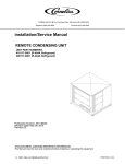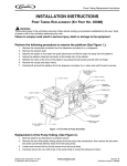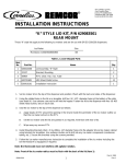
1
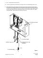
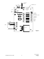
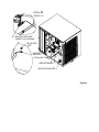
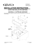
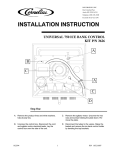
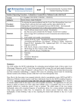
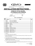
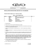
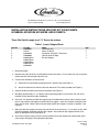
IMI CORNELIUS INC g One Cornelius Place g Anoka, MN 55303-6234
Telephone (800) 238-3600
Facsimile (800) 535-4231
INSTALLATION INSTRUCTIONS, BIN STAT KIT, P/N 631500074,
631500099, 631500108, 631500109, AND 631500116
These Bin Stat kits apply to all “X” Series Ice makers
Table 1. Loose–Shipped Parts
Item No.
1
2
3
4
5
Part No.
630000837
07578
630460162
630900895
620045454 or
620045455 or
620045456 or
620045457 or
620050327
Name
Thermostat Asy
Screw TC 08–32
Installation Instruction, Thermostat
Hex Nut 8–32 SS Keps
Bin Stat Support
Qty.
1
2
1
1
1
1. Disconnect power.
2. Remove front cover of the unit and the electrical box cover plate. For 22” wide units you will need to
remove the Grill from the right side of the unit.
3. To mount bin thermostat in electrical box:
A.
Route wires and connector through grommet in electrical box (see Figure 1).
B.
Attach bin thermostat to electrical box with two 08–32 TC screws provided (see Figure 1).
4. Connect the bin thermostat lead to the circuit board (see Figure 2).
5. Straighten approximately 12” of capillary tube to go through hole in chassis base. Re–coil the remainder. Do not disturb the tightly coiled end.
6. Insert the “1/4” diameter wire Bin Stat support into the coiled end of capillary tube. Carefully wrap 5
turns of free capillary tube tightly around the Bin Stat support. Insert the assembly through the hole
in the chassis base. Route capillary tube to follow the Bin Stat support as closely as possible (see
Figure 3).
7. Slip eye of Bin Stat support over the 8–32 weld stud in the chassis base. If a nut exists on this weld
stud remove before assembling the Bin Stat support. Secure the Bin Stat support with the 8–32
Keps nut provided in the kit (see Figure 3).
8. Any excess capillary tubing must be carefully pulled back into the compressor compartment to prevent ice from damaging it during dispenser operation.
IMI CORNELIUS INC. 2001–2003
1
October 9, 2003
630460162
Rev C
9. Seal ½” diameter hole with sealant (RTV).
10. Turn bin stat adjustment screw clockwise until it stops. Then turn it counterclockwise 1/8 of a turn.
11. Reinstall the front cover of the electrical box and the ice machine and reconnect the power. Verify
that the Bin Stat is working by holding ice on the coiled bare capillary tube. The bin stat will allow the
ice machine cycle to complete and harvest ice. Then the ice machine will shut down. Remove the ice
from the capillary tube and warm the tube with hand heat. The ice machine should start in approximately 60 seconds. Reinstall front cover and grill (22” units only).
ELECTRICAL BOX ASY
TO CIRCUIT BORD
THERMOSTAT KIT ASY
SCREW TC 08–32
631500074
COIL
TO CHASSIS BASE
Figure 1
IMI CORNELIUS INC. 2001–2003
2
October 9, 2003
630460162
Rev C
(White Lead)
Condenser Sensor
See note 1
ERROR
DELAY
PRESSURE Transducer
CLEAN
Harvest
RD
Unit
Selection
Switch
Bridge
Thickness
pot.
Off
321
On
Micro
Processor
(Manufacturing Date)
36430001
Off
S3–1
S3–2
Adjust
J9
On
Valve
#8
#7
GR
Dump
#6
GR
Comp
#4
WATER PUMP
GR
Pump
#3
HOT GAS
#2
NEUTRAL
#1
POWER
Bin
Switches
N
S
4
LH Evap.
Switch
YL
YL
3
YL
2
Plug Bin Thermostat on Top
Two Pins of Stacking Cable Plug
COMPRESSOR
GR
YL
5
FAN MOTOR (AIR COOLED)
#5
RH Evap.
N
S
DUMP VALVE
GR
Fan
GR
Gas
Switch
FILL VALVE
In
Out
Com
Transformer
Stack
Triac
1
Figure 2
IMI CORNELIUS INC. 2001–2003
3
October 9, 2003
630460162
Rev C
A
DETAIL
SCALE 1:2
BIN STAT SUPPORT
INSERT COIL AROUND
8–32 HEX
NUT
BIN STAT
SUPPORT
CAPILLARY TUBE
A
SEE DETAIL
BIN STAT SUPPORT
Figure 3