1
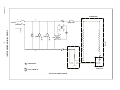
IMI CORNELIUS REMCOR INC g 500 REGENCY DRIVE g GLENDALE HEIGHTS, IL 60139–2268 Telephone (800) 551–4423 Facsimile (800) 519–4423 CHILLER (“CH” SERIES) Models: CH 250 CH 251 Operator’s Manual Part No. 620914801 February 16, 1999 Revised: August 12, 2002 Revision C THIS DOCUMENT CONTAINS IMPORTANT INFORMATION This Manual must be read and understood before installing or operating this equipment IMI CORNELIUS INC; 1999–2002 PRINTED IN U.S.A TABLE OF CONTENTS Page GENERAL INFORMATION . . . . . . . . . . . . . . . . . . . . . . . . . . . . . . . . . . . . . . . . . . . . . . . . . . 1 INTRODUCTION . . . . . . . . . . . . . . . . . . . . . . . . . . . . . . . . . . . . . . . . . . . . . . . . . . . . . . 1 UNPACKING AND INSPECTION . . . . . . . . . . . . . . . . . . . . . . . . . . . . . . . . . . . . . . . . 1 DESIGN DATA . . . . . . . . . . . . . . . . . . . . . . . . . . . . . . . . . . . . . . . . . . . . . . . . . . . . . . . . 1 DATA PLATE INFORMATION . . . . . . . . . . . . . . . . . . . . . . . . . . . . . . . . . . . . . . . . . . . 1 CHILLER INSTALLATION . . . . . . . . . . . . . . . . . . . . . . . . . . . . . . . . . . . . . . . . . . . . . . . 2 LOCATION OF CHILLER . . . . . . . . . . . . . . . . . . . . . . . . . . . . . . . . . . . . . . . . . . . . . . 2 ELECTRICAL CONNECTIONS . . . . . . . . . . . . . . . . . . . . . . . . . . . . . . . . . . . . . . . . . 2 START UP . . . . . . . . . . . . . . . . . . . . . . . . . . . . . . . . . . . . . . . . . . . . . . . . . . . . . . . . . . . . 2 PROCESS WATER FLOW, UNITS WITH PUMP AND TANK (STANDARD) . . 2 PROCESS WATER FLOW, UNITS WITHOUT RESERVOIR (OPTIONAL) . . . 3 THERMOSTAT ADJUSTMENT . . . . . . . . . . . . . . . . . . . . . . . . . . . . . . . . . . . . . . . . . . 3 STANDARD THERMOSTAT . . . . . . . . . . . . . . . . . . . . . . . . . . . . . . . . . . . . . . . . . . . . 3 CHILLER MAINTENANCE . . . . . . . . . . . . . . . . . . . . . . . . . . . . . . . . . . . . . . . . . . . . . . 4 CONDENSER . . . . . . . . . . . . . . . . . . . . . . . . . . . . . . . . . . . . . . . . . . . . . . . . . . . . . . . . 4 FAN MOTOR . . . . . . . . . . . . . . . . . . . . . . . . . . . . . . . . . . . . . . . . . . . . . . . . . . . . . . . . . 4 PUMP MOTOR . . . . . . . . . . . . . . . . . . . . . . . . . . . . . . . . . . . . . . . . . . . . . . . . . . . . . . . 4 CIRCULATION SYSTEM . . . . . . . . . . . . . . . . . . . . . . . . . . . . . . . . . . . . . . . . . . . . . . 4 FILTERS/STRAINERS . . . . . . . . . . . . . . . . . . . . . . . . . . . . . . . . . . . . . . . . . . . . . . . . 4 FLUID RECOMMENDATION . . . . . . . . . . . . . . . . . . . . . . . . . . . . . . . . . . . . . . . . . . . . . . . . 5 TROUBLESHOOTING . . . . . . . . . . . . . . . . . . . . . . . . . . . . . . . . . . . . . . . . . . . . . . . . . . . . . . 6 CHILLER DOES NOT OPERATE, CONTROL POWER LIGHT “OFF” . . . . . . . . . 6 PUMP DOES NOT OPERATE, BUT POWER LIGHT IS “ON”. . . . . . . . . . . . . . . . 6 UNIT RUNS CONTINUOUSLY, BUT IS NOT COOLING PROCESS WATER ENOUGH. . . . . . . . . . . . . . . . . . . . . . . . . . . . . . . . . . . . . . . . . . . . . . . . . . . . . . 6 WARRANTY . . . . . . . . . . . . . . . . . . . . . . . . . . . . . . . . . . . . . . . . . . . . . . . . . . . . . . . . . . . . . . 9 LIST OF FIGURES FIGURE 1. SAMPLE DATA PLATE . . . . . . . . . . . . . . . . . . . . . . . . . . . . . . . . . . . . . . . 1 FIGURE 2. EXTERNAL RESERVOIR WATER LEVEL . . . . . . . . . . . . . . . . . . . . . . 3 FIGURE 3. WIRING DIAGRAM (115V) . . . . . . . . . . . . . . . . . . . . . . . . . . . . . . . . . . . . 6 FIGURE 4. WIRING DIAGRAM (230V) . . . . . . . . . . . . . . . . . . . . . . . . . . . . . . . . . . . 7 FIGURE 4. CABINET SECTION EXPLODED VIEW . . . . . . . . . . . . . . . . . . . . . . . . 8 TABLE OF CONTENTS TABLE 1. DESIGN DATA . . . . . . . . . . . . . . . . . . . . . . . . . . . . . . . . . . . . . . . . . . . . . . . i 1 620914801 GENERAL INFORMATION INTRODUCTION The REMCOR ”CH” Series Recirculating Water Chiller is designed to provide an accurate, reliable, and user– friendly system for cooling a continuous flow of water and keep it at a constant temperature in various closed loop or tank cooling applications. The ”CH” Series Chiller consists of an air–cooled refrigeration system housed in a sturdy sheet metal frame and cabinet. A standard pump and insulated water reservoir package provides a complete liquid cooling and circulating system. The ”CH” Series Chiller is designed to operate in a clean laboratory or industrial environment where ambient temperatures range from 40 to100° F (5 to 38° C). With proper installation, operation, and maintenance, the ”CH” Series Chiller will provide years of trouble free service. UNPACKING AND INSPECTION This unit was thoroughly inspected before leaving the factory and the carrier has accepted and signed for it. Any damage or irregularities should be noted at the time of delivery and immediately reported to the carrier. Request a written inspection report from the Claims Inspector to substantiate any necessary claims. In the event that an immediate replacement is necessary, please contact REMCOR Chiller Sales at 1–800–551–4423. DESIGN DATA Table 1. Design Data CH250 CH251 Cooling Capacity: BTU/hr (W) at 80_ F(27_ C) and 70_ F (21_ C) Liquid Temperature. 3,000 (879) 3,000 (879) Compressor Horsepower .25 (.2 kW) .25 (.2 kW) 115/1/60 7.5 Amps 230/1/60 3.8 Amps R134a R134a 17.125” X 14.125” X 13.375” (43.5 cm X 35.9 cm X 34cm) 17.125” X 14.125” X 13.375” (43.5 cm X 35.9 cm X 34cm 1/2” FPT (S/S) 0.6 (2.72) 1/2I FPT (S/S) 0.6 (2.72) 225 225 Electrical Data: Voltage/Phase/Hertz/Amperage Refrigerant Type: Physical Dimensions, Width X Depth X Height Fittings: Process Connections Optimum Process Liquid Flow GPM (Liters/Min) Condenser Air Flow (CFM) DATA PLATE INFORMATION REMCOR PRODUCTS COMPANY GLENDALE HEIGHTS, IL. 60139–2268 MADE IN U.S.A. PART NO. VOLTS MODEL NO. HZ PH SERIAL NO. AMPS R134A BAR CODE FIGURE 1. SAMPLE DATA PLATE 1 620914801 When servicing a REMCOR Chiller, it is important to note the information contained on the data plate located in the upper rear of the Unit. If technical assistance is needed, the phone technician will need the Serial Number of your Chiller. That information is found on the Data Plate along with the model number, voltage requirement, and refrigerant information. The serial Number is also needed when replacement parts are being ordered or for warranty claims. See CHILLER WARRANTY PAGE. Be sure to include the serial number on any documentation or billing information. CHILLER INSTALLATION Location of Chiller THE CHILLER MUST BE LOCATED NEAR A PROPERLY GROUNDED ELECTRICAL OUTLET. THE CIRCUIT SHOULD BE FUSED AND NO OTHER ELECTRICAL APPLIANCE SHOULD BE CONNECTED TO THE CIRCUIT. ALL ELECTRICAL WIRING MUST CONFORM TO NATIONAL AND LOCAL ELECTRICAL CODES. The Chiller must be located in a well ventilated, indoor area where ambient temperatures will remain above 40_ F (5_ C) and will never increase above 100_ F (38_ C). To obtain optimum cooling capacity, the ambient temperature should be at or below 80_ F (27_ C). It is very important that the air intake and discharge sides of the chiller are not obstructed by other free standing objects. A minimum of two feet of space on all four sides of the chiller will be sufficient to prevent air flow obstructions. It is also important to direct any hot air discharge from other equipment away from the air intake side of the chiller. Condenser air entering the “CH” unit should be below 100_ F (38_ C) .Condenser air temperatures above 100_ F (38_ C) can cause the high pressure safety control to shut down the unit. Electrical Connections (see Figure 3) All wiring must conform to the National Electric Code and any applicable local codes. The Chiller must be permanently wired by means of electrical conduit to a properly fused disconnect of proper amperage or wired to a properly rated power cord and plugged into an outlet with the appropriate disconnect and amperage rating. The electrical junction box, located on the back panel of the Chiller, includes a four terminal strip for power supply connection. The data plate, located next to the junction box, includes the actual voltage, phase, and amperage of the Chiller. START UP WARNING: Never operate the Chiller with it’s panels removed. Always use the power switch to turn off the Chiller when it is not being used. Always ensure that all air inlets and outlets are free from obstruction. Be sure that the reservoir is filled with fluid prior to powering up the unit (see Fluid Recommendations page). Process Water Flow, Units with Pump and Tank (Standard) Follow standard plumbing practices and local codes in making water connections. The Chiller inlet and outlet connections are 3/4”. Flexible hose and fittings are recommended for plumbing the system. A No. 20 mesh strainer should be installed on the Chiller inlet to prevent foreign particles from entering the system and should be cleaned monthly. Lines should be routed with as few bends as possible. Prevent lines from running near 620914801 2 radiators, hot water pipes, etc. Any lengths of tubing that are exposed to high ambient temperatures should be insulated to prevent condensation and/or significant liquid heat loss. After ensuring that the system is free from the obstruction, that all valves are open, and the reservoir when available is full, push the CONTROL POWER switch to the “ON” position. The pump should now be operating. Process Water Flow, Units Without Reservoir (Optional) Follow standard plumbing practices and local codes in making water connections. The Chiller inlet and outlet connections are 3/4”. Flexible hose and fittings are recommended for plumbing the system. A No. 20 mesh strainer should be installed on the Chiller inlet to prevent foreign particles from entering the system and should be cleaned monthly. Lines should be routed with as few bends as possible. Prevent lines from running near radiators, hot water pipes, etc. Any lengths of tubing that are exposed to high ambient temperatures should be insulated to prevent condensation and/or significant water heat loss. Proper priming of the water lines is essential to prevent pump cavitation. Be certain all air has been purged from the lines before operating the pump for an extended period of time. Be sure to remove any loops in the lines that may trap air. The pump must have a supply of water with the level of the water above the inlet of the Chiller. The supply tank must feed the Chiller from the side of the tank below the water level (see Figure 2). CHILLER INLET LINE WATER LEVEL EXTERNAL RESERVOIR CHILLER W/O TANK CORRECT CHILLER INLET LINE CHILLER INLET LINE WATER LEVEL CHILLER W/O TANK WATER LEVEL EXTERNAL RESERVOIR CHILLER W/O TANK CHILLER INLET LINE CHILLER W/O TANK WATER LEVEL EXTERNAL RESERVOIR EXTERNAL RESERVOIR WATER LEVEL IS BELOW CHILLER INLET AIR CAN BE TRAPPED IN CHILLER INLET INCORRECT INCORRECT WATER FEEDING FROM TOP OF TANK INCORRECT FIGURE 2. EXTERNAL RESERVOIR WATER LEVEL THERMOSTAT ADJUSTMENT Standard Thermostat The following procedure should be followed to adjust the standard thermostat: 3 620914801 1. Push the “SET” button located to the right of the digital display. The current set-point will be displayed. 2. Push the “UP” or “DOWN” button until the desired set-point is displayed. 3. After approximately 3 seconds, the display will show the system water temperature. The set-point can be viewed at any time by pressing the “SET” button. The thermostat has a range that has been pre-set at the factory. The range is 40° F (5° C) to 100° F (38° C). If operation outside of this range is required, please contact the Remcor Technical Service Department. UP 5F DOWN SET CHILLER MAINTENANCE WARNING: Disconnect electrical power to the Chiller to prevent personal injury before attempting any internal maintenance. Only qualified personnel should service the internal components or electrical wiring. Condenser On air–cooled Chillers, the CONDENSER FINS should be cleaned by blowing compressed air through the condenser from the fan side. Dirt and debris accumulate on the condenser fins over time, and this build up can severely reduce the performance of the Chiller. Cleaning of the CONDENSER COIL FINS should be done approximately every three months, depending upon cleanliness of your application. Fan Motor On air–cooled Chillers, the condenser FAN MOTOR should be lubricated every 6 months with a few drops of SAE 10 oil. Pump Motor The PUMP MOTOR should be lubricated with thirty drops of SAE 20 oil once a year. Circulation System The CIRCULATION SYSTEM should be drained and flushed periodically to avoid build up and a possible flow restriction caused by contaminants. Filters/Strainers The STRAINER at the Chiller inlet should be removed and cleaned monthly. The “Y” STRAINER, located inside the unit at the inlet of the pump, should be cleaned periodically depending on applications. If a reduction in flow or cavitation of the pump occurs, remove the strainer, flush it out with water, then replace. 620914801 4 FLUID RECOMMENDATION Remcor Chillers are designed to operate with water to provide maximum performance for temperatures of 40_F–100_F. Distilled Water Acceptable De–Ionized Water (1–5 MEG/OHMS) Acceptable De–Ionized Water (5+MEG/OHMS) Acceptable with Stainless Steel & PVC only *No Copper or Brass Propylene Glycol (Lab & Industrial Grade) Acceptable – 30% Glycol/70% Water *For Applications with Temperatures below 40_F Lab & Industrial Grade Ethylene Glycol Acceptable – 30% Glycol/70% Water *For Applications with Temperatures below 40_F Mineral/Hydraulic Oils (Viscosity<50 Centistrokes) Acceptable Ethylene Glycol (Commercial/Automotive Antifreeze) NOT Acceptable *Silicate Rust Inhibitors in Automotive/Commercial Antifreeze will damage pump seals and housing which lead to failure. Acidic/Basic Solutions (Above 8/Below 6 PH) Not Acceptable Mineral/Hydraulic Oils (Viscosity>50 Centistrokes) Not Acceptable For questions regarding special or other fluids contact IMI Cornelius Remcor at 800–551–4423. To Purchase Lab or Industrial Glycol contact: Hubbard Hall (800) 648–3412 – Dow Therm SR1 available in 5 gallon IMI Cornelius (800) 551–4423 – Part# 111521000 5 gallons 5 620914801 TROUBLESHOOTING WARNING: Disconnect electrical power to the Chiller to prevent personal injury before attempting any internal maintenance. Only qualified personnel should service internal components or electrical wiring. If repairs to the Chiller must be made, disconnect electrical power to the unit, then shut off the water source. TROUBLE CHILLER DOES NOT OPERATE, CONTROL POWER LIGHT “OFF” PUMP DOES NOT OPERATE, BUT POWER LIGHT IS “ON”. UNIT RUNS CONTINUOUSLY, BUT IS NOT COOLING PROCESS WATER ENOUGH. PROBABLE CAUSE REMEDY A. No Power To Unit. A. Check Main disconnect fuses, wiring, and power lead to unit. B. Defective Control Power Switch. B. Replace Switch C. Defective Control Transformer. C. Replace Transformer D. Wrong Voltage Supplied to Unit. D. Supplied Voltage Must be within ± 10% of nameplate rating. A. Line to or from Chiller is restricted. A. Inspect lines and remove any obstructions. B. Internal or external filter is blocked with debris. B. Remove and clean strainer, then replace. C. Pump Contactor is defective. C. Replace Contactor. D. Damaged pump motor or impeller. D. Replace pump motor or impeller. A. Condenser is restricted. A. Clean condenser. B. Unit low on refrigerant. B. Call Service. C. Inefficient compressor. C. Call Service. D. Unit is undersized for application. D. Call REMCOR Chiller Sales Rep. NOTE: When servicing a REMCOR Chiller, it is important to note all information provided on the DATA PLATE located in the upper rear of the unit. If technical assistance is needed, the REMCOR Service Technician will need this information along with any description of the problem(s) you are encountering. The serial number and other information will also be required when ordering replacement parts and any other Warranty Claims. 620914801 6 COMPRESSOR 1 3 115/1/60 PUMP C M FAN 115V 5 1 8 9 OVERLOAD M 6 24V 7 4 M S R M COMPRESSOR LIGHT, POWER ON START RELAY START CAPACITOR ELECTRICAL WIRING DIAGRAM FIGURE 3. WIRING DIAGRAM (115V) 7 620914801 620914801 COMPRESSOR 3 1 230/1/60 C M OVERLOAD 2 5 1 8 9 8 FIGURE 4. WIRING DIAGRAM (230V) M 6 PUMP 4 FAN 230V 24V 7 M S R M COMPRESSOR START RELAY LIGHT, POWER ON ELECTRICAL WIRING DIAGRAM START CAPACITOR 4 17 2 16 1 6 3 14 15 7 5 18 8 10 11 12 13 9 FIGURE 5. CABINET SECTION EXPLODED VIEW Item No. Part No. Item No. Name Part No. Name 1 32386 Temperature Controller 10 31962 Fan Motor 2 31934 Power Switch 11 31488 Fan Blade 3 61014 Evaporator 12 620023503 Panel, Right Side 4 620023502 Wrapper Panel 13 60576 Condenser 5 51882 Priming Reservoir Ass’y 14 33082 Relay 6 24388 Panel, Left Side 15 32378 Transformer 7 60992 Compressor 16 32588 Temperature Probe 8 31955 Pump 17 620023504 Panel, Front 9 24390R Base Ass’y 18 24389 Shroud, Condenser 9 620914801 WARRANTY IMI Cornelius Inc. warrants that all equipment and parts are free from defects in material and workmanship under normal use and service. For a copy of the warranty applicable to your Cornelius, Remcor or Wilshire product, in your country, please write, fax or telephone the IMI Cornelius office nearest you. Please provide the equipment model number, serial number and the date of purchase. IMI Cornelius Offices AUSTRALIA D P.O. 210, D RIVERWOOD, D NSW 2210, AUSTRALIA D (61) 2 533 3122 D FAX (61) 2 534 2166 AUSTRIA D AM LANGEN FELDE 32 D A-1222 D VIENNA, AUSTRIA D (43) 1 233 520 D FAX (43) 1-2335-2930 BELGIUM D BOSKAPELLEI 122 D B-2930 BRAASCHAAT, BELGIUM D (32) 3 664 0552 D FAX (32) 3 665 2307 BRAZIL D RUA ITAOCARA 97 D TOMAS COELHO D RIO DE JANEIRO, BRAZIL D (55) 21 591 7150 D FAX (55) 21 593 1829 ENGLAND D TYTHING ROAD ALCESTER D WARWICKSHIRE, B49 6 EU, ENGLAND D (44) 789 763 101 D FAX (44) 789 763 644 FRANCE D 71 ROUTE DE ST. DENIS D F-95170 DEUIL LA BARRE D PARIS, FRANCE D (33) 1 34 28 6200 D FAX (33) 1 34 28 6201 GERMANY D CARL LEVERKUS STRASSE 15 D D-4018 LANGENFELD, GERMANY D (49) 2173 7930 D FAX (49) 2173 77 438 GREECE D 488 MESSOGION AVENUE D AGIA PARASKEVI D 153 42 D ATHENS, GREECE D (30) 1 600 1073 D FAX (30) 1 601 2491 HONG KONG D 1104 TAIKOTSUI CENTRE D 11-15 KOK CHEUNG ST D TAIKOKTSUE, HONG KONG D (852) 789 9882 D FAX (852) 391 6222 ITALY D VIA PELLIZZARI 11 D 1-20059 D VIMARCATE, ITALY D (39) 39 608 0817 D FAX (39) 39 608 0814 NEW ZEALAND D 20 LANSFORD CRES. D P.O. BOX 19-044 AVONDALE D AUCKLAND 7, NEW ZEALAND D (64) 9 8200 357 D FAX (64) 9 8200 361 SINGAPORE D 16 TUAS STREET D SINGAPORE 2263 D (65) 862 5542 D FAX (65) 862 5604 SPAIN D POLIGONO INDUSTRAIL D RIERA DEL FONOLLAR D E-08830 SANT BOI DE LLOBREGAT D BARCELONA, SPAIN D (34) 3 640 2839 D FAX (34) 3 654 3379 USA D ONE CORNELIUS PLACE D ANOKA, MINNESOTA D (763) 421-6120 D FAX (763) 422-3255 LD004 4/21/98 620914801 10 IMI CORNELIUS INC. CORPORATE HEADQUARTERS: One Cornelius Place Anoka, Minnesota 55303-6234 (763) 421-6120 (800) 238-3600 9 620914801


![Service Manual VA13 Carbonator [ 002818 ]](http://vs1.manualzilla.com/store/data/006013608_1-0f8f87056a0ab013b1dd01dac3912d47-150x150.png)