1
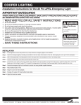
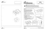
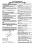
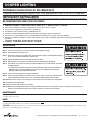
COOPER LIGHTING
Installation Instructions for the StairLite II
Fluorescent Motion Sensing Emergency Light. Field adjustable to Bi-Level or All On/All Off operation.
IMPORTANT SAFEGUARDS
WHEN USING ELECTRICAL EQUIPMENT, BASIC SAFETY PRECAUTIONS SHOULD ALWAYS
BE OBSERVED INCLUDING THE FOLLOWING:
1.
2.
3.
4.
5.
6.
7.
8.
READ AND FOLLOW ALL SAFETY INSTRUCTIONS
Do not use in hazardous locations, in plenum areas, or near gas or electric heaters.
Do not use this equipment for other than the intended use.
Installation is to be performed only by qualified personnel.
Install in accordance with National Electric Code and local regulatory agency requirements.
The use of accessory equipment not recommended by the manufacturer may cause an unsafe condition.
Equipment should be mounted in locations and at heights where it will not readily be subjected to tampering by unauthorized
personnel.
SAVE THESE INSTRUCTIONS
INSTALLATION
Step 1 Turn off power supply where unit is to be installed
Step 2 Loosen the screws that secure the end caps and remove both end caps.
Step 3 Remove both lenses from the unit.
Step 4 Remove the channel cover. Unplug the connector from the charger circuit board that attaches
to the sensor circuit board inside the channel cover.
Step 5 Remove appropriate knockout to bring power into the fixture.
Step 6 Mount the unit securely in place through the four holes provided in the backplate.
Step 7 The StairLite 2 is sent from the factory configured for bi-level (one on with motion, one always
on) lamp operation.
• To change from bi-level lamp operation to all on/all off with motion, remove the hot wire on
ballast B from the hot pigtail. Add this wire to the wire nut containing the hot wire from
ballast A, and the switched lead from the PCB.
Step 8 Connect the battery plug to the printed circuit board
Step 9 Connect the power supply in accordance to local codes. Wire connections as follows: Green
lead to ground, Black lead to hot (see step 7 and wiring diagram), White lead to neutral.
Step 10 Install channel cover, be sure to plug the connector from the sensor PCB to the charger PCB.
Step 11 Install the lens and endcaps.
Step 12 Turn on power, and operate the test button.
Step 13 Adjust the sensitivity and time delay to satisfy installation requirements. For maximum energy conservation, turn the timer to the
minimum. For maximum lamp life and occupant convenience, set the timer to maximum.
MAINTENANCE
Replace the batteries every 8 to 10 years according to ambient conditions. However, we recommend that the equipment be tested regularly in
accordance with local codes.
NOTE
Servicing of any parts should be performed by qualified personnel. ONLY use replacement parts and batteries supplied by Cooper Lighting.
For replacement lamps, battery, or PC board, see the fixture label.
CAUTION: When performing service on the unit that requires removing the channel cover, the battery should be unplugged, as well as removing
AC power, to avoid damaging the circuit board.
Customer First Center 1121 Highway 74 South Peachtree City, GA 30269
4/07
11677542
COOPER LIGHTING
OPERATION
Step 1 Lamps or one lamp (bi-level unit) should come on with motion and stay on during a preset amount of time set by the installer.
Step 2 To test, depress test switch. One lamp should come on to simulate power failure.
Step 3 Release switch and lamp should extinguish.
Wiring Diagram for Bi-Level Operation
LAMP B
SWITCHED
SWITCHED
PCBA
HOT WIRE (BLACK)
BATTERY
ORANGE
(277V)
HOT
NEUTRAL
BLACK
(120V)
BALLAST A
WHITE
(NEUTRAL)
TRANSFORMER
HOT
NEUTRAL
BALLAST B
NEUTRAL WIRE (WHITE)
LAMP A
TROUBLESHOOTING
This unit is equipped with a led indicators for diagnostics purposes.
The following diagram shows the failure indications:
1
2
3
Ac Sense
4
5
TEST
Failure indicators on:
Solution:
Area of Sensor
Recognition
1. Top Lamp Failure . . . . . . . . . . . . . . . . . . . . . . Replace top lamp
2. Bottom Lamp Failure . . . . . . . . . . . . . . . . . . . Replace bottom lamp
3. Sensor Failure . . . . . . . . . . . . . . . . . . . . . . . . Assure that the sensor board is
connected to the charger board.
Replace if connected.
30° **
There are two other LED indicators for reference:
4. Power Indicator . . . . . . . . . . . . . . . . . . . . . . . On when power is supplied
5. Motion Indicator . . . . . . . . . . . . . . . . . . . . . . . Blinks on/off with motion detection
Mounting Height
7.5’
20’ **
Customer First Center 1121 Highway 74 South Peachtree City, GA 30269
4/07
11677542