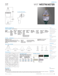
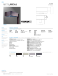
1
POLES
SSA SQUARE STRAIGHT ALUMINUM
8'—35' MOUNTING HEIGHT
4
ACCESSORIES [Base with hand hole and door]
MH
(mounting height)
3
Bolt cover at
all four anchor
bolt locations
(force fit)
Bolt cover (shown in place)
flush with casting surface
S P E C I F I C AT I O N F E AT U R E S
1 ... 356-T6 cast aluminum alloy shoe base with aluminum
alloy knock-in bolt covers.
2 ... 2" x 4" flush hand hole assembly with internal reinforcing
frame (4" Shaft). 2 1/2" x 4" flush hand hole assembly
(5", 6", and 6 3/4" shaft). Ground lug located opposite
hand hole opening drilled & tapped for 3/8" 16NC-2
grounding screw.
2
handhole
12 5/16 "
1
4 ... Drilled or Tenon (specify).
5 ... Anchor bolt per ASTM A576 with (1) nut, (1) flat washer,
and (2) shims. Nuts, washers and threaded portion of bolt
are hot dip galvanized.
3 ... Straight square shaft 6005-T6 aluminum alloy polished
finish.
B
F O U R B O LT A N C H O R A G E [ S e e o r d e r i n g i n f o r m a t i o n ]
BC=Bolt Circle
BP=Bolt Projection
AB=Bolt Dimensions
D=Bolt Diameter
H=Bolt Dimensions
Base View
S
BC
FINISH COLORS [See ordering information. Other finish colors available.]
D
BP
5
AB
H
B=Clear Anodized
C=Dark Bronze Anodized
D=Black Anodized
E=Medium Bronze Anodized
F=Dark Bronze Powder Coat
V=Grey Powder Coat
W=White Powder Coat
X=None (natural aluminum)
Y=Black Powder Coat
WARNING: THE USE OF UNAUTHORIZED ACCESSORIES SUCH AS BANNERS, SIGNS OR PENNANTS FOR WHICH THE POLE WAS NOT DESIGNED FOR VOIDS THE COOPER LIGHTING
WARRANTY AND MAY RESULT IN POLE FAILURE CAUSING SERIOUS INJURY OR PROPERTY DAMAGE. COOPER LIGHTING'S POLE WARRANTY IS ALSO VOIDED IF
LUMINAIRE IS NOT INSTALLED AT TIME OF POLE INSTALLATION.
178 S T R E E T W O R K S O u t d o o r L i g h t i n g S o l u t i o n s
Cooper Lighting
SQUARE STRAIGHT ALUMINUM POLES
O R D E R I N G I N F O R M AT I O N
SAMPLE NUMBER: SSA4T08WXM1XG
Square
S
Straight
S
Shaft
Dia.
(at base)
4
Aluminum
A
Wall
Thickness
T
Mounting
Height
(Ft.)
08
Base
Type
W
Fixture
Mounting
& Type
M
Finish
X
No. &
Location
of Arms
1
Arm
Lengths
X
Accessories
(Ground
Lug)
G
Catalog
Number 3
Shaft
Size
(In.)
B
Wall
Thickness
(In.)
Bolt
Proj.
(In.)
BP
Bolt
Circle
Dia.
(In.)
BC
Anchor Bolt
D x AB x H
(In.)
AB
Net.
Wt.
(Lbs.)
8
SSA4T08WX
4
.125
1 3/4
9
3/4 x 17 x 3
23
25.0 18.6 14.0 10.7
21.0 15.5 11.6 8.9
350
10
SSA4T10WX
4
.125
1 3/4
9
3/4 x 17 x 3
28
19.0 13.7 10.0 7.3
16.5 11.8 8.6
6.3
260
12
SSA4T12WX
4
.125
1 3/4
9
3/4 x 17 x 3
32
24.0 17.5 13.2 10.0
20.8 15.2 11.3 8.6
260
15
SSA4T15WX
4
.125
1 3/4
9
3/4 x 17 x 3
39
12.9 8.9
11.3 7.8
200
15
SSA4M15WX
4
.188
1 3/4
9
3/4 x 17 x 3
55
15
SSA5T15WX
5
.125
2
11
3/4 x 17 x 3
18
SSA4T18WX
4
.125
1 3/4
9
18
SSA4M18WX
4
.188
1 3/4
9
18
SSA5T18WX
5
.125
2
18
SSA5M18WX
5
.188
20
SSA4M20WX
4
.188
20
SSA5T20WX
5
.125
Mtg.
Height
(Ft.)
MH
EPA (Sq. Ft.) 2, 4
At Pole Top
70
80
90
6.1
Max. Fixture
EPA (Sq. Ft.) 2, 4
Load—Include
18" Above Pole Top Bracket (Lbs.)
100 70
80
90
100
4.2
5.4
3.7
20.7 15.0 11.0 8.1
18.5 13.0 9.7
7.2
200
52
23.0 16.4 11.7 8.5
20.3 14.5 10.5 7.6
260
3/4 x 17 x 3
46
8.3
5.1
2.9
1.3
7.6
4.6
2.6
1.2
100
3/4 x 17 x 3
66
14.3 9.7
6.5
4.2
13.0 8.8
5.9
3.8
150
11
3/4 x 17 x 3
61
15.9 10.5 6.9
4.3
14.4 9.5
6.2
3.9
150
2
11
3/4 x 17 x 3
85
25.6 18.2 13.0 9.2
23.5 16.4 11.6 8.3
260
1 3/4
9
3/4 x 17 x 3
72
11.0 6.9
4.1
2.1
10.0 6.3
3.7
1.9
150
2
11
3/4 x 17 x 3
66
12.3 7.5
4.2
1.9
11.1 6.8
3.9
1.7
100
20
SSA5M20WX
5
.188
2
11
3/4 x 17 x 3
94
21.0 14.3 9.7
6.3
19.5 13.2 8.8
5.8
150
25
SSA5M25WX
5
.188
2
11
3/4 x 17 x 3
115
11.6 6.5
--
10.8 6.0
--
100
25
SSA6M25WX
6
.188
2
12 1/2
1 x 36 x 4
140
21.5 13.4 7.6
3.4
20.0 12.4 7.1
3.4
260
30
SSA6X30WX
6
.250
2
12 1/2
1 x 36 x 4
215
18.7 10.8 5.4
1.5
17.6 10.0 5.0
1.4
260
2.8
2.6
30
SSA9X30WX
6 3/4
.250
2 3/4
14 1/4
1 x 36 x 4
237
30.0 19.0 11.6 6.2
28.0 18.0 11.0 6.0
260
35
SSA6X35WX 1
6
.250
2
12 1/2
1 x 36 x 4
249
11.9 4.9
--
--
11.0 4.5
--
--
100
35
SSA9X35WX 1
6 3/4
.250
2 3/4
14 1/4
1 x 36 x 4
274
17.5 8.6
2.5
--
16.7 8.3
2.3
--
150
NOTES: 1 Factory installed vibration dampeners.
2 The above E.P.A. capacities are based on loading from (1994) and pole drag coefficients from (2001) American Association of State Highway and Transportation Officials Specification.
3 Catalog item includes one set of anchor bolts, single nuts and (2) leveling shims.
4 EPAs based on shaft properties with wind normal to flat. EPAs calculated using base wind velocity as indicated plus 30% gust factor.
D R I L L I N G PAT T E R N
Type “M” [RCL, Landau, Galleria and Vision]
Type “E” [Concourse III]
2 13/16''
2 5/16''
2 7/16''
3/4'' dia.
hole
Type “Z” [Credenza and Cirrus]
4" [102mm]
3/4'' dia.
hole
2 7/16" [62mm]
7/8''
4 7/8" [124mm]
4 7/8''
3 7/8''
(2) 3/8"
dia. holes
(2) 5/8''
dia. holes
9/16" [14mm]
dia. hole (3)
M A C H I N I N G F O R R E C TA N G U L A R A R M S [ A d d a s s u f f i x ]
Designation
Letter & Number
M1
M2
M3
M4
M5
Designation
Letter & Number
E1
E2
E3
E4
E5
Designation
Letter & Number
Z1
Z2
Z3
Z4
Z5
Quantity
& Location
Single
2 @ 180°
3 @ 120°
4 @ 90°
2 @ 90°
NOTES: Refer to Fixture Drilling Options on page 160.
MOUNTING OPTIONS [Add as suffix]
Fixed Tenon
Designation
Number
2
5
4
O.D.
LENGTH
ACCESSORIES
O.D.
(In.)
2 3/8
3
4
Length
(In.)
4
4
6
A=1/2" tapped hub 1
B=3/4" tapped hub 1
G=Grounding lug (max. wire #8 AWG)
H=Additional hand hole and cover—
12" below pole top—90° from hand hole.
V=Vibration Damper
NOTES: 1 Location is 3' above base–90° from hand hole.
NOTE: Specifications and dimensions subject to change without notice.
Cooper Lighting
STREETWORKS Outdoor Lighting Solutions
179