1
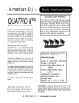
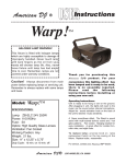
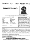
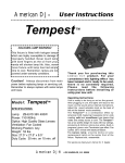
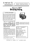
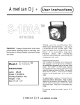
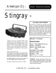
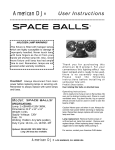
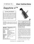
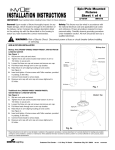
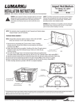
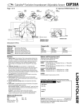
Epic/Wall Mounted
Fixtures
TM
INSTALLATION INSTRUCTIONS
Sheet 1 of 4
10/18/05
IMPORTANT: Read carefully before installing fixture. Retain for future reference.
General: Upon receipt of fixture thoroughly inspect for any
freight damage, which should be brought to the attention of
the delivery carrier. Compare the catalog description listed
on the packing slip with the fixture label on the housing to
assure you have received the correct merchandise.
IMI-658
Safety: This fixture must be wired in accordance with
the national electrical code and applicable local codes
and ordinance. Proper grounding is required to insure
personal safety. Carefully observe grounding procedure
under installation section. All work should be done by a
qualified electrician.
WARNING: Risk of Electric Shock. Disconnect power at fuse or circuit breaker before installing
or servicing.
ARM INSTALLATION
Bishop Arm
Bishop Arm (SA6001-SA6002, SA6050-SA6051, SA6101-SA6102
& SA6150-SA6151)
See Figure 1.
1. Secure arm mount flush with wall using 3/8” hardware supplied
by others.
2. Remove wireway cover screws and wireway cover.
3. Mount arm to arm mount positioning service leads in wireway.
Insert and tighten four screws to 80 in/lbs.
4. Pull fixture leads through arm.
5. Align locating pin and socket when raising fixture to arm.
See Figure 2.
6. Insert and tighten 4 fixture screws with Teflon washers, provided
in polybag, to 80 in/lbs.
7. Connect fixture leads to service leads in wireway.
8. Resecure wireway cover with wireway cover screws tightened to
50 in/lbs.
Traditional Arm (SA6003-SA6004, SA6052-SA6053, SA6103SA6104 & SA6152-SA6153)
See Figure 3.
1. Secure arm mount flush with wall using 3/8” hardware supplied
by others.
2. Remove wireway cover screw and wireway cover.
3. Mount arm to arm mount positioning service leads in wireway.
Insert and tighten set screw to 80 in/lbs.
4. Pull fixture leads through arm.
5. Align locating pin and socket when raising fixture to arm.
See Figure 2.
6. Insert and tighten 4 fixture screws with Teflon washers, provided
in polybag, to 80 in/lbs.
7. Connect fixture leads to service leads in wireway.
8. Resecure wireway cover with wireway cover screw tightened to
50 in/lbs.
Backplate Med
Bishop Wall
Fixture Screws (4)
Teflon Washer (4)
(4) 3/8-16 x 1-1/4
Button Head Cap
Screws
(4) 3/8" Lag Bolts
(supplied by others)
Wireway Cover
Wireway Cover
Srews (2)
Fig. 1
Modern Top
Aligning Pin
Aligning Socket
Fig. 2a
These instructions do not claim to cover all details or variations in the equipment, procedure, or process described, nor to provide directions for meeting every possible
contingency during installation, operation or maintenance. When additional information is desired to satisfy a problem not covered sufficiently for user’s purpose, please
contact your nearest representative.
Customer First Center • 1121 Hwy 74 South • Peachtree City, GA 30269
IMI-658
ADW051684
TM
INSTALLATION INSTRUCTIONS
IMPORTANT: Read carefully before installing fixture. Retain for future reference.
Epic/Wall Mounted
Fixtures
Sheet 2 of 4
10/18/05
FIXTURE MAINTENANCE
A. Relamping
IMI-658
Classical Top
Horizontally lamped
1. Loosen two door screws.
2. Lower door to tethered resting position. See Figure 4.
3. Install suitable lamp. Consult re-lamp label and lamp
instructions for details. Do not overtighten.
4. Raise door and secure with screws.
Aligning Socket
Aligning Pin
Vertically lamped
1. Loosen and remove ring retaining screws globe retaining
ring and globe. Components are not tethered.
See Figure 5. (closeup of lowered globe and ring)
2. Install suitable lamp. Consult re-lamp label and lamp
instructions for details. Do not overtighten.
3. Reinstall ring retaining screws securing globe retaining ring
and globe. In the case of type 3 refractive glass globe, use
the mark on globe bottom for orientation.
Fig. 2b
B. Starter and Fuse Replacement (Where applicable)
Traditional Arm
Arm Mount
Horizontally lamped
1. Loosen two door screws.
2. Lower door to tethered resting position. See Figure 4.
3. Loosen thumbscrew until rectangular washer can be rotated
90 degrees. See Figure 6.
4. Rotate reflector faceplate to release from screws using key
hole slots.
5. Unplug optic quick-disconnect.
6. Remove two screws on ballast cover followed by ballast
cover. See Figure 7.
7. For starter replacement, remove the plug-in starter from
receptacle and replace.
For fuse replacement, unscrew fuse holder cap and replace
fuse. Resecure fuse holder cap.
8. Resecure the ballast cover with the two screws.
9. Plug optic quick-disconnect and secure reflector by keyhole
slots and thumbscrew.
10. Raise door and secure with screws.
Mounting Hardware
(supplied by others)
Fixture Screws
Wireway Cover Screws
Teflon Washers
Wireway Cover
Fig. 3
Options
Flat Lens or Sag Lens
Fig. 4a
Door Screws
Customer First Center • 1121 Hwy 74 South • Peachtree City, GA 30269
IMI-658
ADW051684
TM
INSTALLATION INSTRUCTIONS
IMPORTANT: Read carefully before installing fixture. Retain for future reference.
Epic/Wall Mounted
Fixtures
Sheet 3 of 4
10/18/05
IMI-658
WARNING: Risk of Electric Shock. Disconnect power at fuse or circuit breaker before installing
or servicing.
Vertically lamped
1. Loosen and remove ring retaining screws globe retaining ring
and globe. Components are not tethered.
See Figure 5.
2. Remove two screws on ballast cover followed by ballast
cover. See Figure 7.
3. Unplug optic quick-disconnect.
4. For starter replacement, remove the plug-in starter from
receptacle and replace.
For fuse replacement, unscrew fuse holder cap and replace
fuse. Resecure fuse holder cap.
5. Plug optic quick-disconnect.
6. Resecure the ballast cover with the two screws.
7. Reinstall ring retaining screws securing globe retaining ring
and globe. In the case of type 3 refractive glass globe, use the
mark on globe bottom for orientation.
Fig. 4b
Options
Flat Lens or Sag Lens
Tether
Door Screws
Option MA
C. Power Pack Replacement
Horizontally lamped
1. Loosen two door screws.
2. Lower door to tethered resting position. See Figure 4.
3. Loosen thumbscrew until rectangular washer can be rotated
90 degrees. See Figure 6.
4. Rotate reflector faceplate to release from screws using key
hole slots.
5. Unplug optic quick-disconnect.
6. Remove two screws on ballast cover followed by ballast
cover. See Figure 7.
7. Unplug service quick-disconnect.
8. Holding the handle, loosen the two screws holding the power
pack to the fixture housing. See Figure 8.
9. Holding the handle, rotate the power pack until free and lower.
10. Holding replacement power pack by handle, raise onto screw
heads and rotate.
11. Tighten the two screws while holding power pack in position.
12. Plug together the service quick-disconnect.
13. Resecure the ballast cover with the two screws.
14. Reconnect optic quick-disconnect and secure reflector by
keyhole slots and thumbscrew.
15. Raise door and secure with screws.
Ring Retaining Screws
Globe Retaining Ring
Fig. 5a
Globe
Options
3R & 5R
Ring Retaining Screws
Globe Retaining Ring
Fig. 5b
Globe
These instructions do not claim to cover all details or variations in the equipment, procedure, or process described, nor to provide directions for meeting every possible
contingency during installation, operation or maintenance. When additional information is desired to satisfy a problem not covered sufficiently for user’s purpose, please
contact your nearest representative.
Customer First Center • 1121 Hwy 74 South • Peachtree City, GA 30269
IMI-658
ADW051684
Epic/Wall Mounted
Fixtures
TM
INSTALLATION INSTRUCTIONS
Sheet 4 of 4
10/18/05
IMPORTANT: Read carefully before installing fixture. Retain for future reference.
IMI-658
WARNING: Risk of Electric Shock. Disconnect power at fuse or circuit breaker before installing
or servicing.
Vertically lamped
1. Loosen and remove ring retaining screws globe retaining
ring and globe. Components are not tethered.
See Figure 5.
2. Remove two screws on ballast cover followed by ballast
cover. See Figure 6.
3. Unplug optic quick-disconnect.
4. Unplug service quick-disconnect.
5. Loosen the two screws holding the power pack to the
fixture housing. See Figure 7.
6. Holding the power pack by the handle, rotate the power
pack until free and lower.
7. Holding replacement power pack by handle, raise onto
screw heads and rotate.
8. Tighten the two screws while holding power pack in
position.
9. Plug together the service quick-disconnect.
10. Plug together the optic quick-disconnect.
11. Resecure the ballast cover with the two screws.
12. Reinstall ring retaining screws securing globe retaining ring
and globe. In the case of type 3 refractive glass globe, use
the mark on globe bottom for orientation.
Ballast Cover
Screws
Optic
QuickDisconnect
Fig. 7a
Fuse
Starter
Handle
Service
Quick-Disconnect
Fig. 7b
Keyhole Slot
Rectangular Washer
Reflector
Removal
Thumbscrew
Screws
Fig. 6
Power Pack Removal
Fig. 8
These instructions do not claim to cover all details or variations in the equipment, procedure, or process described, nor to provide directions for meeting every possible
contingency during installation, operation or maintenance. When additional information is desired to satisfy a problem not covered sufficiently for user’s purpose, please
contact your nearest representative.
Customer First Center • 1121 Hwy 74 South • Peachtree City, GA 30269
IMI-658
ADW051684