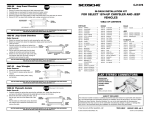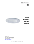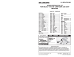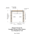
1
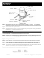
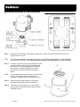
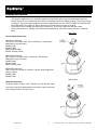
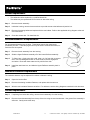
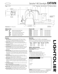
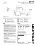
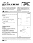
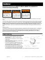
Portfolio ®
Installation Instructions for MD6xT6, MD6xT4, MD6CPxT6 and MD6CPxT4
Commercial Recessed Housings
Risk Of Electrical Shock
Risk Of Fire
Risk Of Fire.
Disconnect power at fuse or
circuit
breaker
before
installing or servicing.
Supply conductors (power
wires) connecting the fixture
must be rated minimum
90°C. If uncertain, consult an
electrician.
Do not install insulation
within 3 inches (76 mm) of
any part of the fixture or in a
way that may entrap heat.
CAUTION: To avoid possible electrical shock, be sure that power supply is turned off before installing or servicing this
fixture.
CAUTION: Metal halide lamps have arc tubes that operate at extremely high temperatures and may shatter unexpectedly
as a result of misapplication, system failure or internal factors. This violent failure could cause extremely hot glass
and lamp parts to discharge into the surrounding environment, creating a risk of personal injury, fire or property
damage. Therefore, it is incumbent on the user to use common sense and good judgment in anticipation of these
potential violent failures. Never use or operate this fixture without safety glass or lens properly installed and secured in
place.
Reduction of Risk
The potential of violent failure can be significantly reduced by relamping at or before the rated end of life. In applications
where the lamps burn continuously, the lamps should be turned off for a period of 15 minutes at least once per week
which will cause lamps nearing their end of life to fail passively upon relighting. Careful adherence to the above
precautions may not eliminate all possible risks associated with the use of Metal Halide lamps, but it will reduce the
likelihood of personal injury or property damage.
Rough-In Mounting
•
•
•
•
•
This fixture should be supported by main runners or
other structure that is capable of supporting fixture
weight of 17lbs.
The junction box will accept both ½” and ¾” trade size
metal conduit.
Review fixture labeling to make sure it is rated for the
voltage installation being used.
The housing is designed for installation where it will
not come in contact with insulation. Thermal insulation
must be kept a minimum of three inches (3”) away
from the housing sides, top and junction box.
This housing/trim is designed to be used with T6/T4.5
Ceramic Metal Halide lamps for the specified wattages
only. These lamps can cause serious skin burn and
eye inflammation from shortwave ultraviolet radiation if the envelope of the lamp is broken or punctured.
704530 Rev. A
-1-
Customer First Center · 1121 Highway 74 South · Peachtree City, GA 30269
Portfolio ®
Step 1.
Install fixture into ceiling cavity using ½” electrical conduit, ¾” channel, 1½” channel or “ x ½” bar stock as
mounting rails (furnished by others) by inserting them into hanger brackets at both ends of the fixture as shown.
Step 2.
Secure mounting rails to support structures.
Step 3.
Adjust fixture so bottom of plaster ring is flush with finished ceiling line, using screws securing hanger brackets.
Hanger bracket is reversible for a total adjustment of 5”.
Electrical Connection
CAUTION: Make certain no bare wires are exposed outside of wire nut connectors.
Step 4.
Provide electrical service according to the “National Electrical Code” or your local electrical code to the junction
box (located on the plaster frame). Supply wire insulation must be rated for at least 90° C. The junction box is
also rated for a maximum of 12 No. 12 AWG Branch Circuit conductors suitable for at least 90°C.
Step 5.
Remove junction box cover.
Step 6.
Remove appropriate round pryout and connect conduit to junction box with proper connector (not included).
Step 7.
Connect supply lead wires to junction box lead wires (line, neutral and ground) in fixture using properly sized
wire nuts (not included). Be careful not to leave any bare conductors outside of the wire nut connectors.
Step 8.
120V or 277V AC Supply: Connect white to white, black to black and green (from electrical service) to the bare
copper wire in the junction box. See the appropriate wiring diagram for more detail.
Place all connections and excess wiring into the junction box and replace cover.
704530 Rev. A
-2-
Customer First Center · 1121 Highway 74 South · Peachtree City, GA 30269
Portfolio ®
Distribution Selection & Trim Installation
Step 1.
Install the proper lamp type and wattage into the socket. Make sure the new lamp does not have any
fingerprints, dust, lint, etc.
NOTE:
The lamp-socket assembly is installed onto the trim in one of three possible positions. These are labeled
Narrow, Medium and Wide. The selected position determines the light distribution from the fixture.
Step 2.
As shown in figure at right, the trim assembly includes
six plastic lockout inserts. Remove and discard the
two lockouts from the desired distribution positions.
For example, if a Medium distribution is desired,
remove the two lockouts closest to the “Medium”
labels.
NOTE:
It is intended that the remaining plastic lockouts remain
in place. This will help avoid any inadvertent
distribution changes during re-lamping in the future.
Step 3.
Secure the lamp-socket assembly in the desired
distribution position with the two thumbscrews.
Step 4.
Install the trim into the housing. The trim’s torsion
springs pass through slots in torsion spring receivers
inside the housing.
704530 Rev. A
-3-
Customer First Center · 1121 Highway 74 South · Peachtree City, GA 30269
Portfolio ®
Lamping Information
•
•
•
The electronic ballast has a very important shutdown timing feature that turns off the ballast output after time
periods ranging from 2 minutes up to 30 minutes if a lamp does not start or operate properly or if the fixture wiring
is improper. For proper system diagnosis and at lamp replacement time, the INPUT POWER TO THE BALLAST
MUST BE RESET (turn power off, wait 10 seconds, turn power back on) to start a new lamp.
Take proper care in handling and disposing of the old lamp. Do not touch glass bulb with bare hands.
Lamp contains Mercury. Manage in accordance with disposal laws. See www.lamprecycle.org or 1-866-6666850.
Main Lamp
Ceramic Metal Halide Lamp
MD6xT6G12 Housings
G12 socket for one 20W, 39W, 70W or 150W lamp. Generic lamp
designations (lamp by others):
M156/E (20W)
M130/E (39W)
M98/E, M139/E (70W)
M102/E, M142/E (150W)
MD6xT4G85 Housings
G8.5 socket for one 20W, 39W, or 70W lamp. Generic lamp
designations (lamp by others):
M156/E (20W)
M130/E (39W)
M98/E, M139/E (70W)
MD6xT4G65 Housings
GU6.5 socket for one 20W or 39W lamp. Generic lamp designations
(lamp by others):
M156/E (20W)
M130/E (39W)
Quartz Lamp
Quartz Restrike Lamp
The Quartz lamp is a 100W, 120V, T4 Bulb with a “DC Bayonet” base.
This housing may be re-lamped either from below or above the ceiling.
Allow sufficient time for the lamp to cool.
704530 Rev. A
-4-
Customer First Center · 1121 Highway 74 South · Peachtree City, GA 30269
Portfolio ®
To re-lamp from below the ceiling:
Step 1.
Remove the lower trim by gently pulling the trim
down until the torsion spring stops are reached.
Remove the trim from the torsion spring receivers.
Step 2.
Remove the socket assembly from the top of the
trim using the two thumbscrews. Use gloves if the
assembly is still warm. Gently remove the old
lamp. Dispose the old lamp according to local
recycling code.
Step 3.
Install the new lamp. Make sure the new lamp
does not have any fingerprints, dust or lint.
Step 4.
Re-assemble the socket assembly back onto the
trim. Be sure to re-assemble the lamp
assembly in the same distribution as before
(Narrow, Medium or Wide). Secure with the two
thumbscrews.
Step 5.
Install the trim back into the housing using the
torsion springs.
To re-lamp from above the ceiling:
Step 1.
Remove the top cover.
Step 2.
Remove the socket assembly from the top of the
trim using the two thumbscrews. Use gloves if the
assembly is still warm. Gently remove the old
lamp. Dispose the old lamp according to local
recycling code.
Step 3.
Install the new lamp. Make sure the new lamp
does not have any fingerprints, dust or lint.
Step 4.
Re-assemble the socket assembly back onto the
trim. Be sure to re-assemble the lamp
assembly in the same distribution as before
(Narrow, Medium or Wide). Secure with the two
thumbscrews.
Step 5.
Install the trim back into the housing using the torsion springs.
704530 Rev. A
-5-
Customer First Center · 1121 Highway 74 South · Peachtree City, GA 30269
Portfolio ®
Ballast Replacement
•
•
The ballast should be replaced by a qualified electrician.
The ballast may be replaced either from below or above the ceiling.
Step 1.
Remove the trim assembly.
Step 2.
Inside the housing, remove the access door to provide access to the ballast and junction box.
Step 3.
Remove the existing ballast and replace with the new ballast. Refer to the applicable wiring diagram at the end
of this document.
Step 4.
Close the access door. Re-install the trim.
Lens Maintenance & Replacement
Do not operate without the lens in place. These lamps require the containment
provided by the lens. These lamp types can only be used in enclosed luminaires, for
which the lens is required.
Step 1.
Remove the trim assembly from the housing.
Step 2.
Slide the Upper Reflector assembly off of the Lower Reflector assembly.
Step 3.
To Clean Lens: Gently wipe with a soft, clean, dry, lint free cloth to remove
dust. Use mild detergent solution on a soft cloth to remove fingerprints
and stains. Rinse with clean water and dry with lint free cloth.
Step 4.
Install the new/clean lens, and slide the Upper Reflector assembly back in
place.
Insulation Detector Replacement
The insulation detector may be replaced from above or below the ceiling.
Step 1.
Open the Junction Box.
Step 2.
Remove the existing Insulation Detector, and replace with the new one.
Step 3.
Wire the new Insulation Detector as before. For reference, see the wiring diagrams contained in this document.
Socket Replacement
Step 1.
If replacing from below the ceiling, remove the trim assembly from the housing.
Step 2.
Remove the socket assembly from the top of the trim using the two thumbscrews. Use gloves if the assembly is
still warm. Gently remove the lamp.
704530 Rev. A
-6-
Customer First Center · 1121 Highway 74 South · Peachtree City, GA 30269
Portfolio ®
Step 3.
Remove the socket from the bracket by removing the two Philips screws which secure it in place.
Step 4.
Install the new socket using the original screws.
Step 5.
Install the lamp. Make sure the lamp does not have any fingerprints, dust or lint.
Step 6.
Re-assemble the socket assembly back onto the trim. Be sure to re-assemble the lamp assembly in the
same distribution as before (Narrow, Medium or Wide). Secure with the two thumbscrews.
Step 7.
Install the trim back into the housing using the torsion springs.
Wiring Diagrams
1. For Housings with Ballasts requiring dedicated voltage input. Includes Catalog Numbers MD6xxx1E and MD6xxx2E.
704530 Rev. A
-7-
Customer First Center · 1121 Highway 74 South · Peachtree City, GA 30269
Portfolio ®
2. For Housings with Ballasts requiring dedicated voltage input, and a Quartz Restrike System. Includes Catalog
Numbers MD6xxx1EQ and MD6xxx2EQ.
3. For Housings with Ballasts requiring dedicated voltage input, and an Emergency Circuit Quartz Lamp. Includes
Catalog Numbers MD6xxx1EX and MD6xxx2EX.
704530 Rev. A
-8-
Customer First Center · 1121 Highway 74 South · Peachtree City, GA 30269
Portfolio ®
4. For Housings with Universal voltage input, 120-277V, with Advance Ballast (70W). Includes Catalog Numbers
MD6xxxG12E, MD6xxxG85E and MD6xxxG65E.
5. For Housings with Universal voltage input, 120-277V, with Advance Ballast (70W) and a Quartz Restrike System.
Includes Catalog Numbers MD6xxxG12EQ, MD6xxxG85EQ and MD6xxxG65EQ.
704530 Rev. A
-9-
Customer First Center · 1121 Highway 74 South · Peachtree City, GA 30269
Portfolio ®
6. For Housings with Universal voltage input, 120-277V, with Advance Ballast (70W) and an Emergency Circuit Quartz
Lamp. Includes Catalog Numbers MD6xxxG12EX, MD6xxxG85EX and MD6xxxG65EX.
7. For Housings with Universal voltage input, 120-277V, with Vossloh Schwabe Ballast (20W or 39W). Includes Catalog
Numbers MD6xxxG12E, MD6xxxG85E and MD6xxxG65E.
704530 Rev. A
- 10 -
Customer First Center · 1121 Highway 74 South · Peachtree City, GA 30269
Portfolio ®
8. For Housings with Universal voltage input, 120-277V, with Vossloh Schwabe Ballast (20W or 39W) and a Quartz
Restrike System. Includes Catalog Numbers MD6xxxG12EQ, MD6xxxG85EQ and MD6xxxG65EQ.
9. For Housings with Universal voltage input, 120-277V, with Vossloh Schwabe Ballast (20W or 39W) and an Emergency
Circuit Quartz Lamp. Includes Catalog Numbers MD6xxxG12EX, MD6xxxG85EX and MD6xxxG65EX.
704530 Rev. A
- 11 -
Customer First Center · 1121 Highway 74 South · Peachtree City, GA 30269