1
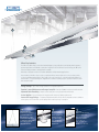
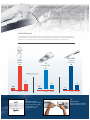
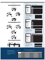
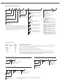
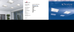
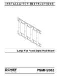
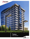
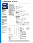
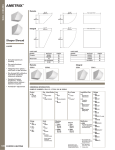
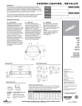
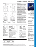
Micro-Bay
Luminaire
1
3
4
5
2
Micro-Bay luminaire
The MB series (Micro-Bay) is a functional and multi-purpose low profile fluorescent high bay that incorporates
premium performance and durable construction. Designed for T5 and T8 fluorescent technology, the MB series
offers both high performance and application versatility.
Micro-Bay is designed for narrow or medium distributions in high mounting applications.
Row mounting of the Micro-bay is easily accomplished with an external rigid section connector that provides
excellent row alignment through the entire length of the row. Suspension is convenient and flexible with the SS
Aircraft Cable “Y” Toggle Mounting Kits. Adjustment for luminaire mounting height is provided at luminaire rather
than structure height.
Energy Savings – Up to 70% energy reduction for comparable light levels.
Superior Lumen Maintenance and Longer Lamp Life – Rated at 25,000+ hours based on 10 hour starts.
Improved Color Rendering – Improves visual acuity for a more pleasant work environment.
Instant Ignition – Easy and inexpensive integration with emergency lighting requirements.
Increased Energy Savings – Programmed Rapid Start ballasts and pre-wired configuration allow for utilization
of Occupancy Sensors with Photo Control ability, further reducing energy consumption.
1
Cable Mounting Kit
Suspension is convenient
and flexible with the SS
Aircraft Cable “Y” Toggle
Mounting Kits. Adjustment
for luminaire mounting height
is provided at luminaire
rather than structure.
2
Occupancy Sensor
Integral occupancy
sensor available and
provides from 600
sq. ft. up to 1250 sq.
ft. of coverage in a
maximum mounting
height of 40'.
3
Reflectors
Highly specular reflectors
for precise light control.
Three optical distribution
patterns are available:
Focus - SC < .9
Task - .9 ≤ SC < 1.2
Normal - 1.2 ≤ SC ≤ 1.4
System Performance
The Micro-Bay series delivers high performance in a streamlined package. The Micro-Bay’s large assortment of
optical distributions meet a wide range of mounting heights and aisle configurations – providing unmatched uniformity
performance. The Micro-Bay is the solution to improving visibility while delivering the lowest watts/sq. ft.
Micro-Bay
PSMH
400 Watt
1 Lamp T8
Focus Beam
I5
30
30
4 Lamp, T5HO
25
Based on: 120' x 10' aisle,
25' mounting height
8
6
2.88
Watts/Sf.ft.
1.51
Horizontal (Avg.) Vertical (5 ft.)
Footcandles
Footcandles
Watts/Sf.ft.
4
Rigid Exterior Connector
Rigid exterior connector/coupling
with pre-punched holes facilitates
easy installation of coupled
sections up to 32' long.
6
.8
Horizontal (Avg.) Vertical (5 ft.)
Footcandles
Footcandles
Watts/Sf.ft.
Horizontal (Avg.) Vertical (5 ft.)
Footcandles
Footcandles
5
Plug-In Connectors
Optional pre-wired factory installed
multiple circuit plug-in connectors.
Dimensions
Photometrics
Coefficients of Utilization
T5 Lamp Configurations
Focus Beam, 1 or 2 Lamp
⊥
X
1-31/32" [51mm]
3-9/32"
[84mm]
X=2-11/16"
[69mm]
1"
[26mm]
4-5/16"
[110mm]
||
Task Beam, 2 Lamp
Task Beam, 1 Lamp
X
X
1"
[26mm]
5-7/8"
[150mm]
1-31/32" [51mm]
3-9/32"
[84mm]
X=2-11/16"
[69mm]
4-5/16"
[110mm]
7-7/32" [184mm]
Normal Beam, 1 or 2 Lamp
X
4-5/16"
[110mm]
Focus Beam, 1 Lamp
Focus Beam, 2 Lamp
X
4-3/16"
[107mm]
1-1/8"
[29mm]
||
29/32"
[24mm]
8-5/8"
[220mm]
Task Beam, 1 or 2 Lamp
X
3-3/8"
[86mm]
29/32"
[24mm]
7-9/16"
[193mm]
105
84
69
57
49
42
37
32
29
26
24
100
87
75
66
59
53
48
44
40
37
34
Zone
0-30
0-40
0-60
0-90
0-180
Lumens
722
1133
2012
2679
2682
%Lamp
25.3
39.8
70.6
94.0
94.1
100
84
71
61
53
46
41
37
34
31
28
100
81
67
56
48
41
36
32
29
26
24
%Fixture
26.9
42.3
75.0
99.9
100.0
3-11/32"
[85mm]
29/32"
[24mm]
7-3/32"
[181mm]
||
Top View
7/8" [23mm] K.O. (3)
Ceiling Stand-Off
Embossments
20%
70
113
102
93
84
77
70
65
60
56
53
49
113
97
84
73
65
58
52
47
43
40
37
113
93
77
65
56
49
43
39
35
32
29
113
89
71
59
49
42
37
33
29
26
24
106
91
79
69
61
55
49
45
41
38
35
106
88
73
62
54
47
42
37
34
31
28
30%
30 10
50
106
85
69
57
48
42
36
32
29
26
24
101
87
76
66
59
53
48
43
40
37
34
101
84
71
61
53
46
41
37
33
30
28
101
82
67
56
48
41
36
32
29
26
23
Zonal Lumen Summary
Zone
0-30
0-40
0-60
0-90
0-180
Lumens
700
1104
2001
2707
2711
%Lamp
24.6
38.7
70.2
95.0
95.1
%Fixture
25.8
40.7
73.8
99.9
100.0
2-11/16"
[69mm]
(8’) 91-3/4" [2330mm]
(4’) 48" [1220mm]
(8’) 96" [2438mm]
Illuminance Estimator
Choose the spacing and mounting
height to determine the average
footcandle and watts per square
foot values.
20%
70
115
108
101
95
88
82
77
72
67
62
58
115
105
96
87
79
72
66
61
56
51
47
115
102
91
81
73
65
59
64
49
44
40
MB-132-FB-UNV-EBT1
Electronic Ballast
(1) 32W T8 Lamp, 2850 lumens
Spacing criterion: (II) 1.2 x mounting
height, (⊥) 0.5 x mounting height
Efficiency 96.8%
Test Report: 09363
1-3/4" x 3-1/4" K.O. (1)
Ground Screw Bump
(4’) 43-3/4" [1112mm]
Effective floor cavity reflectance
80%
50%
50 30 10
50 30 10
rc
rw
RCR
0
1
2
3
4
5
6
7
8
9
10
X
4' and 8'
105
87
73
62
54
47
42
38
34
31
28
Coefficients of Utilization
Normal Beam, 1 or 2 Lamp
X=2-11/16"
[69mm]
105
90
78
69
61
55
49
45
41
38
35
Zonal Lumen Summary
MB-132-TB-UNV-EB81
Electronic Ballast
(1) 32W T8 Lamp, 2850 lumens
Spacing criterion: (II) 1.2 x mounting
height, (⊥) 1.0 x mounting height
Efficiency 95.1%
Test Report: 10266
9-1/16" [231mm]
X=2-11/16"
[69mm]
112
88
71
59
50
43
37
33
29
26
24
Effective floor cavity reflectance
80%
50%
50 30 10
50 30 10
rc
rw
RCR
0
1
2
3
4
5
6
7
8
9
10
X
X=2-11/16"
[69mm]
X=2-11/16"
[69mm]
112
92
77
65
56
49
43
39
35
32
29
30%
30 10
50
Coefficients of Utilization
1-7/16"
[37mm]
T8 Lamp Configurations
5-11/16"
[145mm]
112
97
84
73
65
58
52
47
43
40
37
20%
1-31/32" [51mm]
3-9/32"
[84mm]
X=2-11/16"
[69mm]
112
101
92
84
76
70
65
60
56
52
49
MB-132-NB-UNV-EB81
Electronic Ballast
(1) 32W T8 Lamp, 2850 lumens
Spacing criterion: (II) 1.2 x mounting
height, (⊥) 1.2 x mounting height
Efficiency 94.1%
Test Report: 10267
1-3/16"
[31mm]
X=2-11/16"
[69mm]
Effective floor cavity reflectance
80%
50%
70 50 30 10
50 30 10
rc
rw
RCR
0
1
2
3
4
5
6
7
8
9
10
115
99
87
76
68
60
54
49
44
39
36
108
99
91
83
76
69
64
59
54
49
46
108
97
87
78
71
64
58
53
48
43
40
50
108
95
84
75
66
59
53
48
43
39
35
103
95
88
81
74
68
62
57
53
48
45
30%
30 10
103
94
85
77
69
63
57
52
47
43
39
103
92
82
73
66
59
53
48
43
39
35
Zonal Lumen Summary
0-30
0-40
0-60
0-90
0-180
1251
1758
2535
2759
2759
43.9
61.7
88.9
96.8
96.8
45.3
63.7
91.9
100.0
100.0
Illuminance Levels (FC) & Watts Per Sq. Ft. (LPD)
Micro-Bay
Based on 120 ft. x 10 ft. Aisle
20 ft
25 ft
30 ft
35 ft
40 ft
Qty
FC
LPD
Qty
FC
LPD
Qty
FC
LPD
Qty
FC
LPD
Qty
FC
LPD
MB-132-NB
30
31
0.8
38
32
1.01
44
31
1.17
52
31
1.39
58
30
1.55
MB-154-NB
17
31
0.84
21
31
1.03
24
35
1.18
28
30
1.38
32
30
1.57
MB-232-FB
16
31
0.76
19
30
0.90
23
31
1.09
26
30
1.24
30
30
1.43
MB-254-FB
11
32
0.99
13
31
1.17
16
32
1.44
18
31
1.62
20
30
1.80
MB Ordering Information for T5 and T8
S A M P L E N U M B E R : M B - 1 5 4 T 5 - F B - U N V- E B T 1- U
Voltage
UNV=Universal
120-277 Voltage
UNC=Universal
347/480 Voltage (9)
Blank=4' Length
8T=8' Tandem
Length
Series
MB= Micro-Bay
Options
GL=Single Element Fuse
GM=Double Element Fuse
EL=Emergency Installed (2)
Number of Lamps
1=1 Lamp
2=2 Lamps
Lamp Types
32=32W T8 (48")
54T5=54W T5HO (48")
Reflector
FB=Focus Beam
TB=Task Beam (Medium)
NB=Normal Beam
NOTES: (1) Products also available in non-US voltages and frequencies for international
markets. (2) Voltage to be specified with emergency ballast option.(3) Voltage must be
specified when ordered with plugs, motion or emergency ballasts. (4) Cannot be combined
with PI/CPI option. See below. (5) 2 lamp ballast configurations only in UNC versions.
(6) Not for use in high abuse applications such as gymnasiums. (7) Must ship as accessory
separately. (8) For use with T5HO Focus, Normal or Wide Beam optics only. (9) UNC option
available on select T8 ballast systems. Consult factory.
Ballast Type (1)
T5 Systems
EBT =T5 Linear Electronic Program Rapid
Start. Total Harmonic Distortion < 10%(5)
No. of Ballast
1 or 2
EHT =T5 Linear Electronic Program Rapid Start
High Ambient.
Total Harmonic Distortion < 10%(5)
No. of Ballast
1 or 2
DIM=Dimming
T8 Systems (9)
EB8 =T8 Electronic Instant Start. (5)
Total Harmonic Distortion < 10%
No. of Ballast
1 or 2
EB8 /PLUS= T8 Electronic Instant Start.(5)
High Ballast Factor >1.15.
No. of
Total Harmonic Distortion < 10%
Ballast
1 or 2
ER8 =T8 Electronic Program Rapid Start.
Total Harmonic Distortion < 10%
No. of Ballast
1 or 2
ER8 /PLUS= T8 Electronic Program Start.
High Ballast Factor >1.15.
No. of
Total Harmonic Distortion < 10%
Ballast
1 or 2
DIM=Dimming
Options
PI/CPI=Plug-In (1, 2 or 3)
Specify Circuit
Packaging
U=Unit Pack
(see PI Ordering Information Below)
C3=3' Power Cord (4)
C6=6' Power Cord (4)
PC3-=3' Power Cord & Plug(3), (4)
(Specify Voltage)
PC6-=6' Power Cord & Plug(3), (4)
(Specify Voltage)
Accessories (order separately)
AYC-CHAIN/SET/U=(2) Hooks, 36" Chain
Sets w/S-Hooks (6)
GRIPPLE-Y- =Y Mounting Toggle, #2 Cable
(Specify 10' or 30')
GRIPPLE-TOGGLE- =Single Toggle, #2 Cable
(Specify 10' or 30')
MB-EXT-LONG-CONN-KIT-U= Rigid Connector
Support for Continuous Channel Installation
MS=Aisle Coverage Motion Sensor (3), (7)
MSO=360˚ Coverage Motion Sensor (3), (7)
MB-SENSOR-KIT-CTR/MT-U=Aisle Coverage
Motion Sensor , Center Mount Hardware,
120/277V
MB-SENSOR-KIT-END/MT-U=Aisle Coverage
Motion Sensor , End Mount Hardware,
120/277V
MB-SENSOR-KIT-CTR/480V-U=Aisle Coverage
Motion Sensor , Center Mount Hardware,
480V
MB-SENSOR-KIT-END/480V-U=Aisle Coverage
Motion Sensor, End Mount Hardware, 480V
WG/MB-4FT-T5-NB-B=Wireguard for T5HO(8)
PI Ordering Information
Catalog
Number
Suffix
PI 1 BLK
PI 2 BLU
PI 2 BLK
Number of
Circuits
1
2
2
Circuit
Wired To
Ballast
Black
Blue
Black
PI 3 RED
PI 3 BLU
PI 3 BLK
3
3
3
Red
Blue
Black
Catalog Numbering System
The PI System is available in sections up to 8' in length for continuous row wiring by simply plugging the
sections together. Each PI section is factory wired to the ballast leads. Color coding of wires is as follows:
PI-1 = One Circuit - 2 Wires: one black, one white
PI-2 = Two Circuits - 3 Wires: one black, one blue, one white
PI-3 = Three Circuits - 4 wires: one black, one blue, one red, one white
When ordering the PI2/PI3 System it is necessary to specify the number of fixtures required for each circuit.
Each circuit in fixture must be ordered as a separate line item, with a different hot wire color specified.
All wiring to external feeds, using cord or cord & plug, are responsibility of installing licensed contractor. Cord
and cord & plug sets must be ordered separately if PI option is chosen.
PI1 - Single Circuit Plug-In
P I 2 - Tw o C i r c u i t P l u g - I n
SAMPLE NUMBER: PI1BLK-WG
SAMPLE NUMBER: PI2BLK-WG
PI1= Single
Circuit
BLK=Black Hot
NG= No Ground (ground provided
by fixture body)
WG= With Ground (separate
ground wire in harness)
SAMPLE NUMBER: PI3BLK-WG
BLK=Black Hot
BLU=Blue Hot
RED=Red Hot
Leave Blank=Single
Neutral
/WHT=White Neutral
/GRY=Gray Neutral
BLK=Black Hot
BLU=Blue Hot
Leave Blank=Single
Neutral
/WHT=White Neutral
/GRY=Gray Neutral
PI3 - Three Circuit Plug-In
PI3= Three
Circuit
PI2= Two
Circuit
Leave Blank=Single
Neutral
2NEU=Two Neutrals
NG= No Ground (ground provided
by fixture body)
WG= With Ground (separate
ground wire in harness)
For complete product data, reference the Fluorescent Specification binder. Specifications & dimensions subject to change without notice. Consult your Cooper Lighting Representative for availability
and ordering information.
Leave Blank=Single
Neutral
2NEU=Two Neutrals
NG= No Ground
(ground provided by
fixture body)
WG= With Ground
(separate ground wire
in harness)
Cooper Lighting
Customer First Center
1121 Highway 74 South
Peachtree City, GA 30269
International Sales, USA
Cooper Lighting
1121 Highway 74 South
Peachtree City, GA 30269
P: 770-486-4800
F: 770-486-4801
P: 770-486-4800
F: 770-486-4801
www.cooperlighting.com
Canada
Cooper Lighting
5925 McLaughlin Road
Mississauga, Ontario L5R 1B8
P: 905-507-4000
F: 905-568-7049
Domestic Facilities
Cranbury, New Jersey
Elk Grove Village, Illinois
Irving, Texas
Ontario, California
Peachtree City, Georgia
Canadian Facility
Calgary, Alberta T2E 7V9
Cooper Lighting, Metalux and F-Bay are valuable trademark of Cooper Industries in the United States and other countries.
You are not permitted to use the Cooper Trademarks without the prior written consent of Cooper Industries.
Cooper Lighting
1121 Highway 74 South
Peachtree City, GA 30269
P: 770-486-4800
www.cooperlighting.com
ADF081052
Printed in USA
The Cooper Lighting Family
Halo
Metalux
Lumark
Sure-Lites
Neo-Ray
Corelite
Portfolio
Iris
Shaper
io
Lumière
Invue
McGraw-Edison
Streetworks
Fail-Safe
MWS
DLS
RSA
Ametrix