1
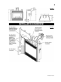
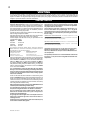
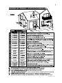
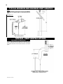
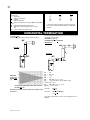
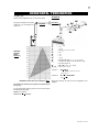
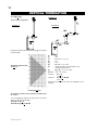
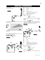
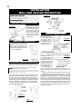
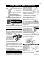
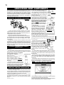
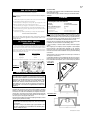
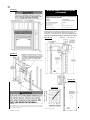
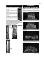
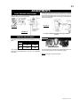
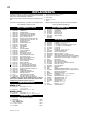
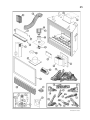
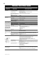
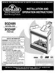
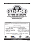
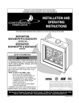
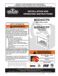
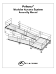
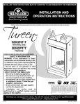
1
W415-0327 / B / 12.07.07
$10.00
W415-0327 / B / 12.07.07
2
TABLE of CONTENTS
PG 2-5
6 - 13
14 - 19
Framing
Minimum Mantel and Enclosure Clearances
Nailing Tab Installation
INTRODUCTION
Warranty
General Instructions
General Information
Care of Glass & Plated Parts
Installation overview
VENTING
Venting Lengths
Minimum Air Terminal Location Clearances
Typical Minimum and Maximum Vent Lengths
Special Vent Installations
Venting Application Flow Chart
Venting Specifics
Horizontal Termination
Vertical Termination
INSTALLATION
Wall and Ceiling Protection
Vent Heat Shield Installation
Horizontal Installation
Adjustable Firestop Installation
Vertical Installation
Using Flexible Vent Components
Horizontal air terminal installations
Vertical air terminal installations
Fireplace Vent Connection
Using Rigid Vent Components
Restricting Vertical Vents
Gas Installation
Optional wall switch installation
Mobile Home Installation
19-20 FINISHING
Log Placement
Charcoal Embers
Vermiculite
Glowing Embers
Logo Placement
Louvre Installation
21
OPTIONAL BLOWER INSTALLATION
21
OPTIONAL FAN INSTALLATION /
GD36 THERMOSTATIC SENSOR CONTROL
22
OPERATION / MAINTENANCE
Operating Instructions
Maintenance
23
ADJUSTMENTS
Pilot Burner Adjustment
Venturi Adjustment
24-25 REPLACEMENTS
Ordering Replacement Parts
Replacement Parts
Vent Kits
Terminal Kits
Accessories
26-27 TROUBLE SHOOTING GUIDE
28
NOTES
PLEASE RETAIN THIS MANUAL
RETAIN THIS MANUAL FOR FUTURE REFERENCE
!
WARNING
• Do not burn wood or other materials in this fireplace.
• Adults and especially children should be alerted to the hazards of high surface temperatures and should stay away to avoid
burns or clothing ignition. Supervise young children when they are in the same room as the fireplace.
• Clothing or other flammable material should not be placed on or near the fireplace.
• Due to high temperatures, the fireplace should be located out of traffic and away from furniture and draperies.
• Ensure you have incorporated adequate safety measure to protect infants/toddlers from touching hot surfaces.
• Even after the fireplace is out, the glass and/or screen will remain hot for an extended period of time.
• Check with your local hearth specialty dealer for safety screens and hearth guards to protect children from hot surfaces. These
screens and guards must be fastened to the floor.
• Any safety screen or guard removed for servicing must be replaced prior to operating the fireplace.
• It is imperative that the control compartments, burners and circulating blower and its passageway in the fireplace and venting
system are kept clean. The fireplace and its venting system should be inspected before use and at least annually by a qualified
service person. More frequent cleaning may be required due to excessive lint from carpeting, bedding material, etc. The fireplace
area must be kept clear and free from combustible materials, gasoline and other flammable vapours and liquids.
• Under no circumstances should this fireplace be modified.
• This fireplace must not be connected to a chimney flue pipe serving a separate solid fuel burning appliance.
• Do not use this fireplace if any part has been under water. Immediately call a qualified service technician to inspect the fireplace
and to replace any part of the control system and any gas control which has been under water.
• Do not operate the fireplace with the glass door removed, cracked or broken. Replacement of the glass should be done by a
licensed or qualified service person.
• Do not strike or slam shut the fireplace glass door.
• This fireplace uses and requires a fast acting thermocouple. Replace only with a fast acting thermocouple supplied by Wolf
Steel Ltd.
• Pressure relief doors must be kept closed while the fireplace is operating to prevent exhaust fumes containing carbon monoxide, from entering into the home. Temperatures of the exhaust escaping through these openings can also cause the surrounding
combustible materials to overheat and catch fire.
• Only doors / optional fronts certified with the unit are to be installed on the appliance.
W415-0327 / B / 12.07.07
3
CONTINENTAL® products are manufactured under the
strict Standard of the world recognized
ISO 9001 : 2000 uality
Q
Assurance Certificate.
CONTINENTAL® products are designed with superior components and materials, assemble
d by trained craftsmen
who take great pride in their work. The burne
r and valve assembly are leak and test-fir
ed at a qua
lity test tation.
s
Once assembled the completefireplace is thoroughly inspected by a qualified technician before packaging
ensure
to
that you, the customer, receives the quality product that you expect
m WOLF
fro
STEEL Ltd..
CONTINENTAL® GAS FIREPLACE PRESIDENT'S LIFETIME LIMITED WARRANTY
The following materials and workm
work
manship
anship in your newCONTINENTAL® gas fireplace are
warranted against defects for as long as you
ownn owthe fir
e place. This
covers: combusti
combustio
combusti
onn
fireplace.
Th
is covers:
steel burner, phazer™
phazer™ logs
chamber, heat exchanger, stainlesssteel
logs and
and embers,
embers, ceramic
ceramic glass
ssglass
gla
(thermal breakage only), gold plated
plate
d parts
parts
against tarnishing,
tarnishing, porcelainized
porcelainized enamelled
enamelled compocompoarts
p against
nents and aluminium extrusion trims.
Electrical (110V and millivolt) mponents
compo
co nents and wearable parts suchas asblowers,
blowers,gasgasva
lves,
valves,
thermal switch, switches, wirin
g, remote controls, igniter,
gask
eting, and
are
wi
ring,
igni
ter, gasketing,
and pilot
pilot assembly
assemb
ly are
covered and WOLF STEEL LTD. will provide replacement parts free of charge during the
first year of the limited warr
anty.
Any labour related to warranty repair is not covered.
CONDITIONS AND LIMITATIONS
WOLF STEEL LTD. warrants its products against manufacturing defects to the original purchaser only -- i.e., the individual or legal entity (registered customer) whose name appears
on the warranty registration card filed with WOLF STEEL Ltd. -- provided that the purchase was made through an authorized CONTINENTAL® dealer and is subject to the following
conditions and limitations:
This factory warranty is nontransferable and may not be extended whatsoever by any of our representatives.
The gas fireplace must be installed by a licenced, authorized service technician or contractor. Installation must be done in accordance with the installation instructions included with
the product and all local and national building and fire codes.
This limited warranty does not cover damages caused by misuse, lack of maintenance, accident, alterations, abuse or neglect and parts installed from other manufacturers will nullify
this warranty.
This limited warranty further does not cover any scratches, dents, corrosion or discolouring caused by excessive heat, abrasive and chemical cleaners nor chipping on porcelain
enamel parts, mechanical breakage of PHAZER™ logs and embers, nor any venting components used in the installation of the fireplace.
WOLF STEEL Ltd. warrants its stainless steel burners against defects in workmanship and material for life, subject to the following conditions: During the first 10 years WOLF STEEL
Ltd. will replace or repair the defective parts at our option free of charge. From 10 years to life, WOLF STEEL LTD. will provide replacement burners at 50% of the current retail price.
In the first year only, this warranty extends to the repair or replacement of warranted parts which are defective in material or workmanship provided that the product has been operated
in accordance with the operation instructions and under normal conditions.
After the first year, with respect to this President's Limited Lifetime Warranty, WOLF STEEL LTD. may, at its discretion, fully discharge all obligations with respect to this warranty
by refunding to the original warranted purchaser the wholesale price of any warranted but defective part(s).
WOLF STEEL Ltd. will not be responsible for installation, labour, or any other costs or expenses related to the reinstallation of a warranted part, and such expenses are not covered
by this warranty.
Notwithstanding any provisions contained in this President's Limited Lifetime Warranty, WOLF STEEL’S responsibility under this warranty is defined as above and it shall not in
any event extend to any incidental, consequential or indirect damages.
This warranty defines the obligations and liability of WOLF STEEL Ltd. with respect to the CONTINENTAL® gas fireplace and any other warranties expressed or implied with respect
to this product, its components or accessories are excluded.
WOLF STEEL Ltd. neither assumes, nor authorizes any third party to assume, on its behalf, any other liabilities with respect to the sale of this product. WOLF STEEL Ltd. will not
be responsible for: over-firing, downdrafts, spillage caused by environmental conditions such as rooftops, buildings, nearby trees, hills, mountains, inadequate vents or ventilation,
excessive venting configurations, insufficient makeup air, or negative air pressures which may or may not be caused by mechanical systems such as exhaust fans, furnaces, clothes
dryers, etc.
Any damages to fireplace, combustion chamber, heat exchanger, brass trim or other component due to water, weather damage, long periods of dampness, condensation, damaging
chemicals or cleaners will not be the responsibility of WOLF STEEL Ltd.
The bill of sale or copy will be required together with a serial number and a model number when making any warranty claims from your authorized dealer. The warranty registration
card must be returned within fourteen days to register the warranty.
WOLF STEEL Ltd. reserves the right to have its representative inspect any product or part thereof prior to honouring any warranty claim.
ALL SPECIFICATIONS AND DESIGNS ARE SUBJECT TO CHANGE WITHOUT PRIOR NOTICE DUE TO ON-GOING PRODUCT IMPROVEMENTS. CONTINENTAL® IS A REGISTERED
TRADEMARK OF WOLF STEEL LTD. PATENTS U.S. 5.303.693.801 - CAN. 2.073.411, 2.082.915. © WOLF STEEL LTD.
W415-0327 / B / 12.07.07
4
GENERAL INSTRUCTIONS
THIS GAS FIREPLACE SHOULD BE INSTALLED AND SERVICED BY
A QUALIFIED INSTALLER to conform with local codes. In absence
of local codes, install the BCDV48 to the current National Fuel Gas
Code, ANSI Z223.1, or the current CAN/CGA B149, Installation
Codes.
Installation practices vary from region to region and it is important
to know the specifics that apply to your area, ie: in Massachusetts
State:
• The fireplace damper must be removed or welded in
the open position prior to installation of a fireplace insert or
gas log.
• The appliance off valve must be a “T” handle gas cock.
• The flexible connector must not be longer than 36".
• The appliance is not approved for installation in a bedroom
or bathroom unless unit is direct-vent.
• WARNING: This product must be installed by a licensed
plumber or gas fitter when installed within the commonwealth of Massachusetts.
Mobile home installation must conform with local codes or in the absence
of local codes, install to the current standard for gas equipped mobile
housing CAN/CSA ZA240 MH Series in Canada or the Manufactured
Home Construction and Safety Standard, Title 24 CFR, Part 3280, or
the Fire Safety Criteria for Manufactured Home Installations, Sites and
Communities Standard ANSI/NFPA 501A in the United States.
The fireplace and its individual shut off valve must be disconnected
from the gas supply piping system during any pressure testing of that
system at test pressures in excess of 1/2 psig (3.5 kPa). The fireplace
must be isolated from the gas supply piping system by closing its
individual manual shut off valve during any pressure testing of the
gas supply piping system at test pressures equal to or less than 1/2
psig (3.5 kPa).
When the fireplace is installed directly on carpeting, vinyl tile or
other combustible material other than wood flooring, the fireplace
shall be installed on a metal or wood panel extending the full width
and depth.
If the optional fan or blower is installed, the junction box must be
electrically connected and grounded in accordance with local codes.
In the absence of local codes, use the current CSA C22.1 CANADIAN
ELECTRICAL CODE in Canada or the ANSI/NFPA 70 NATIONAL
ELECTRICAL CODE in the United States.
GENERAL INFORMATION
FOR YOUR SATISFACTION, THIS FIREPLACE HAS BEEN TESTFIRED TO ASSURE ITS OPERATION AND QUALITY! Maximum input
is 36,000 BTU/hr for natural gas and 36,000 BTU/hr for propane.
When the fireplace is installed at elevations above 4,500ft, and in the
absence of specific recommendations from the local authority having
jurisdiction, the certified high altitude input rating shall be reduced at
the rate of 4% for each additional 1,000ft.
Maximum output is 23,500 BTU/hr at an efficiency of 65%. The maximum A.F.U.E. (annual fuel utilization efficiency) rating is 62%.
Minimum inlet gas supply pressure is 4.5" water column for natural
gas and 11" water column for propane. Maximum inlet gas pressure
is 7" water column for natural gas and 13" water column for propane.
Manifold pressure under flow conditions is 3.5" water column for
natural gas and 10" water column for propane.
This fireplace is approved for bathroom, bedroom and bed-sitting
room installations and is suitable for mobile home installation.
No external electricity (110 volts or 24 volts) is required for the
gas system operation.
Expansion / contraction noises during heating up and cooling
down cycles are normal and are to be expected.
W415-0327 / B / 12.07.07
CARE OF GLASS, AND PLATED PARTS
Do not use abrasive cleaners to clean plated parts. Buff lightly with
a clean dry cloth. The BCDV48 is factory equipped with tempered
glass. The glass thickness is 3/16". Use only replacement glass
available from your Continental® dealer. DO NOT SUBSTITUTE
MATERIALS. Clean the glass after the first 10 hours of operation
with a recommended gas fireplace glass cleaner. Thereafter clean
as required. DO NOT CLEAN GLASS WHEN HOT! If the glass is not
kept clean permanent discolouration and / or blemishes may result.
Use only accessories designed for and listed with your specific fireplace.
Provide adequate ventilation air. Provide adequate accessibility clearance for servicing and operating the fireplace. Never
obstruct the front opening of the fireplace.
For safe and proper operation of the fireplace follow the venting
instruction exactly.
Deviation from the minimum vertical vent length can create difficulty in burner start-up and/or carboning.
Provide a means for visually checking the vent connection to
the fireplace after the fireplace is installed.
In order to avoid the possibility of exposed insulation or vapour
barrier coming in contact with the fireplace body, it is recommended that the walls of the fireplace enclosure be 'finished',
(i.e. drywall/sheetrock) as would any other outside wall of the
home. This will ensure that clearance to combustibles is maintained within the cavity.
Vent lengths that pass through unheated spaces (attics, garages,
crawl spaces) should be insulated with the insulation wrapped
in a protective sleeve to minimize condensation.
Objects placed in front of the fireplace must be kept a minimum
of 48" away from the front face of the unit.
5
FIGURE 1
INSTALLATION OVERVIEW
FIGURE 2
W415-0327 / B / 12.07.07
6
VENTING
For safe and proper operation of the fireplace follow the venting instruction exactly. Deviation from the minimum vertical vent length can
create difficulty in burner start-up and/or carboning. Provide a means for visually checking the vent connection to the fireplace after the
fireplace is installed. Vent lengths that pass through unheated spaces (attic, garages, crawl spaces) should be insulated with the insulation
wrapped in a protective sleeve to minimize condensation.
VENTING LENGTHS
Use only Wolf Steel, Simpson Dura-Vent, Selkirk Direct Temp or
American Metal Amerivent venting components.Minimum and
maximum vent lengths, for both horizontal and vertical installations,
and air terminal locations for either system are set out in this manual
and must be adhered to. For Simpson Dura-Vent, Selkirk Direct Temp
and American Metal Amerivent, follow the installation procedure
provided with the venting components.
All outer pipe joints of these venting systems must be sealed using
Red RTV Hight Temperature Sealant.
Wolf Steel, Simpson Dura-Vent, Selkirk Direct Temp and American
Metal Amerivent venting systems must not be combined.
A starter adaptor must be used and may be purchased from the
corresponding supplier:
Supplier
5&8 ZC
Dura-Vent
W175-0170
Amerivent
4DSC-N2
Direct Temp
5DT-AA
For Simpson Dura-Vent, Selkirk Direct Temp and American
Metal Amerivent, follow the installation procedure found on
the website for your venting supplier:
VENTING SUPPLIER
WEBSITE ADDRESS
Simpson Dura-Vent
www.duravent.com
Selkirk Direct Temp
www.selkirkcorp.com
American Metal Amerivent
www.americanmetalproducts.com
When using Wolf Steel venting components, use only approved Wolf
Steel rigid / flexible components with the following termination kits:
WALL TERMINAL KIT GD422, or 1/12 TO 7/12 PITCH ROOF TERMINAL KIT GD410, 8/12 TO 12/12 ROOF TERMINAL KIT GD411,
FLAT ROOF TERMINAL KIT GD412 or PERISCOPE KIT GD401 (for
wall penetration below grade). With flexible venting, in conjunction
with the various terminations, use either the 5 foot vent kit GD420
or the 10 foot vent kit GD430.
It is recommended to attach the Wolf Steel 45º rigid adaptor
directly to the unit when terminating horizontally off the back
of the unit. This must be done before attaching the desired vent
system. Once this transition has been made, venting systems
must not be combined.
These vent kits allow for either horizontal or vertical venting of the
fireplace. FIGURES 3 & 4. The maximum allowable horizontal run is
20 feet. The maximum allowable vertical vent length is 40 feet. The
maximum number of 5" vent connections is two horizontally or three
vertically (excluding the fireplace and the air terminal connections)
when using aluminium flexible venting.
When terminating vertically, restrictor plate W500-0205 must be
installed. (Refer to Restricting Vertical Vents).
For optimum flame appearance and fireplace performance,
keep the vent length and number of elbows to a minimum.
The air terminal must remain unobstructed at all times. Examine the air terminal at least once a year to verify that it is
unobstructed and undamaged.
Purge all gas lines with the glass door of the fireplace removed.
Assure that a continuous gas flow is at the burner before reinstalling the door.
Under extreme vent configurations, allow several minutes (5-15)
for the flame to stabilize after ignition.
W415-0327 / B / 12.07.07
A terminal shall not terminate directly above a sidewalk or
paved driveway which is located between two single family
dwellings and serves both dwellings. Local codes or regulations
may require different clearances.
Do not allow the inside liner to bunch up on horizontal or vertical runs and elbows. Keep it pulled tight. A 1¼" air gap all
around between the inner liner and outer liner is required for
safe operation. Use a firestop when penetrating interior walls,
floor or ceiling.
HORIZONTAL VENT SECTIONS: A minimum clearance of 2" all
around the vent pipe in all horizontal runs to combustibles is required.
Use firestop spacer W010-1778 (supplied).
VERTICAL VENT SECTIONS: A minimum of 1" all around the vent
pipe on all vertical runs to combustibles is required. Use firestop
spacer W500-0028 (not supplied).
Horizontal runs may have a 0" rise per foot in all cases using
Wolf Steel rigid or flexible vent components or Simpson
Dura-Vent, Selkirk Direct Temp or American Metal Amerivent
vent components.
For optimum performance it is recommended that all horizontal
runs have a 1" rise per foot when using Wolf Steel flexible vent
components.
7
MINIMUM AIR TERMINAL LOCATION CLEARANCES
FIGURE 3
W415-0327 / B / 12.07.07
8
TYPICAL MINIMUM AND MAXIMUM VENT LENGTHS
NOTE:
When terminating vertically, the restrictor plate W5000205 must be installed. Refer to Restricting Vertical
Vents.
FIGURES 4 a-b
SPECIAL VENT INSTALLATIONS
PERISCOPE TERMINATION
Use only GD401 periscope kit to locate the air termination above
grade. The periscope must be installed so that when final grading
is completed, the bottom air slot is located a minimum of 12" above
grade.
FIGURE 5
W415-0327 / B / 12.07.07
9
VENTING APPLICATION FLOW CHART
HORIZONTAL
TERMINATION
vertical rise
is equal to
or greater
than the
horizontal
run
horizontal
run + vertical rise to
maximum
of 40 feet
VERTICAL
TERMINATION
vertical rise
is less than
horizontal
run
vertical rise
is equal to
or greater
than the
horizontal
run
vertical rise
is less than
horizontal
run
h o r i zo n t a l
run + vertical rise to
maximum of
24.75 feet
horizontal
run + vertical rise to
maximum
of 40 feet
horizontal
run + vertical rise to
maximum
of 40 feet
4.2 times the
vertical rise
equal to or
greater than
the horizontal run
3 times the
vertical
rise equal
to or greater than the
horizontal
run
W415-0327 / B / 12.07.07
10
DEFINITIONS
for the following symbols used in the venting calculations and
examples are:
> - greater than
> - equal to or greater than
< - less than
< - equal to or less than
HT - total of both horizontal vent lengths (HR) and offsets (HO)
in feet
HR - combined horizontal vent lengths in feet
HO - offset factor: .03(total degrees of offset - 135°*) in
feet
VT - combined vertical vent lengths in feet
ELBOW VENT LENGTH VALUES
feet
0.03
0.45
0.9
1.35
2.7
1°
15°
30°
45°*
90°*
inches
0.5
6.0
11.0
16.0
32.0
* the first 45º and 90° offset has a zero value and is shown
in the formula as -45° and -90º respectively or -135º when
combined.
HORIZONTAL TERMINATION
when (HT) < (VT)
Simple venting configuration (only one 45º and 90° elbow)
90°
For vent configurations requiring more than one 45º and 90° elbow,
the following formulas apply:
Formula 1: HT < VT
Formula 2: HT + VT < 40 feet
Example 1:
90°
H2
FIGURE 6
V1
FIGURE 7
45º
45º
H1
REQUIRED
VERTICAL
RISE IN FEET
(VT)
CALCULATED HORIZONTAL VENT RUN PLUS OFFSETS IN FEET (HT)
The shaded area within the lines represents acceptable values
for HT and VT .
90°
= 8 ft
V1
VT
= V1 = 8 ft
H1
= 2.5 ft
= 2 ft
H2
HR = H1 + H2 = 2.5 + 2 = 4.5 ft
HO = .03 (one 45º elbow + two 90º elbows - 135º)
=0.3(225-135º) = 2.7ft
HT
= HR + HO = 4.5 + 2.7 = 7.2 ft
HT + VT = 7.2 +8 =15.2ft
Formula 1:
Formula 2:
H T < VT
7.2 < 8
HT + VT < 40 feet
15.2 < 40
Since both formulas are met, this vent configuration is acceptable.
W415-0327 / B / 12.07.07
11
HORIZONTAL TERMINATION
when (HT) > (VT)
Simple venting configuration (only one 45º and 90° elbow)
See graph to determine the required
vertical rise VT for the required horizontal run HT.
FIGURE 8
Example 2:
90°
90°
FIGURE 9
90°
H1
H3
H4
V2
H2
V1
90°
45°
REQUIRED
VERTICAL
RISE IN
INCHES (VT)
V1
V2
VT
H1
H2
H3
H4
HR
HO
HT
HT + VT
= 4 ft
= 1.5 ft
= V1 + V2 = 4 ft + 1.5 ft = 5.5 ft
= 2 ft
= 1 ft
= 1 ft
= 1.5 ft
= H1 + H2 + H3 + H4 = 2 + 1 + 1 + 1. 5 = 5.5 ft
= .03 (one 45º elbow + four 90º elbows -135º)
=.03 (405-135)=8.1ft
= HR + HO = 5.5 + 8.1 = 13.6ft
= 13.6 + 5.5 = 19.1 ft
Formula 1:
Formula 2:
HORIZONTAL VENT RUN PLUS OFFSETS IN FEET
HT < 4.2 VT
4.2 VT = 4.2 x 5.5 = 23.1 ft
13.6 < 23.1
HT + VT < 24.75 feet
19.1 < 24.75
Since both formulas are met, this vent configuration is acceptable.
The shaded area within the lines represents acceptable values
for HT and VT .
For vent configurations requiring more than one 45º and 90° elbow
the following formulas apply:
Formula 1: HT < 4.2 VT
Formula 2: HT + VT < 24.75 feet
W415-0327 / B / 12.07.07
12
VERTICAL TERMINATION
when (HT) < (VT)
Example 3:
Simple venting configurations
V2
FIGURE 10
FIGURE 11
90°
H2
90°
V1
45°
45°
H1
90°
See graph to determine the required vertical rise VT for the required
horizontal run HT.
V1
V2
VT
H1
H2
HR
HO
REQUIRED VERTICAL RISE
IN FEET (VT)
HT
HT + VT
= 5 ft
= 10 ft
= V1 + V2 = 5 + 10 = 15 ft
= 3 ft
= 2.5 ft
= H1 + H2 = 3 + 2.5 = 5.5 ft
= .03 (one 45º elbow + three 90º elbows - 135º)
= .03(45+90+90+90-135)=5.4
= HR + HO = 5.5 + 5.4 = 10.9 ft
= 10.9 + 15 = 25.9 ft
H T < VT
10.9 < 15
Formula 2:
HT + VT < 40 feet
25.9 < 40
Since both formulas are met, this vent configuration is acceptable.
Formula 1:
HORIZONTAL VENT RUN PLUS
OFFSETS IN FEET (HT)
The shaded area within the lines represents acceptable values
for HT and VT.
For vent configurations requiring more than one 45º and one 90°
elbow , the following formulas apply:
Formula 1: HT < VT
Formula 2: HT + VT < 40 feet
W415-0327 / B / 12.07.07
13
VERTICAL TERMINATION
V1
V2
VT
H1
H2
HR
HO
= 1 ft
= 1.5 ft
= V1 + V2 = 1 + 1.5 = 2.5 ft
= 6 ft
= 2 ft
= H1 + H2 = 6 + 2 = 8 ft
= .03 (one 45º elbow + three 90º elbow - 135º)
= .03(45 + 90 + 90 + 90 - 135) = 5.4 ft
HT
= HR + HO = 8 + 5.4 = 13.4 ft
HT + VT = 13.4 + 2.5 = 15.9 ft
when (HT) > (VT)
Simple venting configurations
FIGURE 12
HT < 3VT
3VT = 3 x 2.5 = 7.5 ft
13.4 > 7.5
Since this formula is not met, this vent configuration is unacceptable.
Formula 2:
HT + VT < 40 feet
15.9 < 40
Since only formula 2 is met, this vent configuration is unacceptable and a new fireplace location or vent configuration will
need to be established to satisfy both formulas.
Example 5:
Formula 1:
See graph to determine the required vertical rise VT for the required
horizontal run HT.
REQUIRED
VERTICAL
RISE IN
FEET (VT)
90°
HORIZONTAL VENT RUN PLUS OFFSET IN FEET (HT)
H1 V1 45°
90°
H2
V2
90°
FIGURE 14
V1
V2
VT
H1
H2
H3
HR
HO
H1
H3
90°
For vent configurations requiring more than one 45º and one 90°
elbow , the following formulas apply:
Formula 1: HT < 3VT
Formula 2: HT + VT < 40 feet
45°
H2
45°
The shaded area within the lines represents acceptable values
for HT and VT.
Example 4:
V2
HT
HT + VT
= 1.5 ft
= 8 ft
= V1 + V2 = 1.5 + 8= 9.5 ft
= 1 ft
= 1 ft
= 10.75 ft
= H1 + H2 + H3 = 1 + 1 + 10.75 = 12.75 ft
= .03 (three 90° elbows + two 45° elbow - 135°)
= .03(90 + 90 + 90 + 45 + 45 - 135) = 6.75 ft
= HR + HO = 12.75 + 6.75 = 19.5 ft
= 19.5 + 4.5= 29 ft
HT < 3VT
3VT = 3 x 9.5 = 28.5 ft
19.5 < 28.5
Formula 2:
HT + VT < 40 feet
29 < 40
Since both formulas are met, this vent configuration is acceptable.
Formula 1:
V1
90°
90°
FIGURE 13
W415-0327 / B / 12.07.07
14
INSTALLATION
WALL AND CEILING PROTECTION
HORIZONTAL VENT SECTIONS: A minimum clearance of 2" all
around the vent pipe in all horizontal runs to combustibles is required.
Use firestop spacer W010-1778 (supplied).
VERTICAL VENT SECTIONS: A minimum of 1" all around the vent
pipe on all vertical runs to combustibles is required. Use firestop
spacer W500-0028 (not supplied).
FIGURE 17c
VENT HEAT SHIELD INSTALLATION
The vent heat shield must be
installed only when terminating horizontally with no vertical
rise. Remove the two screws
nearest the vent collars on
the top of the fireplace. Align
the vent heat shield (supplied) and secure. Adjust the
vent heat shield to touch the
firestop spacer.
FIGURE 15
HORIZONTAL INSTALLATION
This application occurs when venting
through an exterior wall. Having determined the air terminal location, cut and
frame a hole in an exterior wall. The
recommended framed opening is 147/16"
W x 161/4" H. See figure16.
FIGURE 16
ADJUSTABLE FIRESTOP INSTALLATION
Apply a bead of caulking all around and place the firestop top, so
that the vent shield covers the top of the vent within the opening.
NOTE: THE FIRESTOP ASSEMBLY MUST BE INSTALLED
WITH THE VENT SHIELD TO THE TOP.
The length of the vent shield may be cut shorter for combustible
walls that are less than 8 1/2" thick but the vent shield must extend
the full depth of the combustible wall.
Place the firestop bottom against the firestop top and secure the
two together. Adjust the assembly to ensure it is tight to the vent.
Secure firestop to wall. This restricts cold air from being drawn
into the room or around the fireplace. Ensure that both spacer and
shield maintain the required clearance to combustibles. Once the
vent pipe is installed in its final position, apply high temperature
sealant W573-0002 (not supplied) between the pipe and the firestop spacer. See figures 17a-c.
VENT
SHIELD
FIRESTOP
TOP
FIGURE 17a
FIRESTOP
BOTTOM
W415-0327 / B / 12.07.07
FIGURE 17b
VERTICAL INSTALLATION
This application occurs
when venting through
a roof. Installation kits
for various roof pitches
are available from your
Continental® dealer. See
Accessories to order the
specific kit required.
FIGURE 18
1. Determine the air
terminal location, cut and frame
123/4" x 123/4" openings in the ceiling and the roof to provide the
minimum 1" clearance between the fireplace pipe / liner and any
FIGURE 19
combustible material. Try
to centre the vent pipe location midway between two
joist to prevent having to
cut them. Use a plumb bob
to line up the centre of the
openings. DO NOT FILL
THIS SPACE WITH ANY
TYPE OF MATERIAL.
A vent pipe shield will
prevent any materials such as insulation, from filling up the 1" air
space around the pipe. Nail headers between the joist for extra
support.
2. Apply a bead of caulking (not supplied) to the framework or
to the Wolf Steel vent pipe shield plate or equivalent (in the case
of a finished ceiling), and secure over the opening in the ceiling.
FIGURE 19. A firestop must be placed on the bottom of each framed
opening in a roof or ceiling that the venting system passes through.
Apply a bead of caulking all around and place a firestop spacer over
the vent shield to restrict cold air from being drawn into the room or
around the fireplace. Ensure that both spacer and shield maintain
the required clearance to combustibles. Once the vent pipe / liner is
installed in its final position, apply sealant between the pipe / liner
and the firestop spacer.
15
USING FLEXIBLE VENT COMPONENTS
Do not allow the inside flexible
vent pipe to bunch up on
ELBOW
horizontal or vertical runs and
elbows. Keep it pulled tight.
A 1 1/4" air gap between the
inner and the outer vent pipe
SPACERS
all around is required for safe
operation. A spacer is required
at the start, middle and end of each elbow to
ensure this gap is maintained.
For safe and proper operation of the fireplace, follow the venting instructions exactly.
All inner exhaust and outer intake vent pipe
joints may be sealed using either Red RTV high
temp silicone sealant or Black high temp Mill
Pac with the exception of the fireplace exhaust flue collar
which must be sealed using Mill Pac (not supplied).
FIGURE 20
Use only approved flexible vent pipe kits marked:
"Wolf Steel Approved Venting" as identified by the stamp only on the 8” outer
vent pipe.
For safe and proper operation of the fireplace, follow the venting
instructions exactly.
NOTE: Eight (8”) inches is the minimum bend radius allowed for
the 8” diameter flexible vent pipe.
HORIZONTAL AIR TERMINAL INSTALLATION
1. Secure the terminal to the terminal extension plate (see figure
21).
2. Stretch the 5" diameter flexible vent pipe to the required length
taking into account the additional length needed for the finished wall
surface. Slip the liner a minimum of 2" over the inner sleeve of the
air terminal and secure with
CAULKING
3 #8 screws. Apply a heavy
bead of the high tempera- #10x2½"
SCREWS
CAULKING
ture sealant W573-0002
(not supplied).
5"FLEX
PIPE
3. Using the 8" diameter
flexible vent pipe, slide over
8" FLEX
PIPE
2" OVERLAP
the outer combustion air
sleeve of the air termiHI-TEMP
SEALANT
nal and secure with 3 #8
TERMINAL
EXTENSION
screws. Seal as before.
FIGURE 21
PLATE
The air terminal mounting
plate may be recessed into the exterior wall
or siding by 1½", the depth of the return flange.
4. Insert the vent pipe assembly through the firestop maintaining
the required clearance to combustibles. Holding the air terminal
(lettering in an upright, readable position), secure to the exterior
wall and make weather tight by sealing with caulking (not supplied).
5. Apply a heavy bead of the high temperature sealant, W573-0007
(not supplied) to the inside of the 5" vent pipe approximately 1" from
the end. Slip the vent pipe a minimum of 2" over the fireplace vent
collar and secure with 3 #8 screws.
6. Using the 8" diameter flexible vent pipe, apply high temperature
sealant W573-0002 (not supplied), slide a minimum of 2" over the
fireplace combustion air collar and secure with 3 #8 screws.
AT
TE
C
A U NT
T I I ON
O
N
C
H
AU
H
D
O
T
VERTICAL AIR TERMINAL INSTALLATION
1. Fasten the roof support to the roof using the screws provided. The
roof support is optional. In this case the venting is to be adequately
supported using either an alternate method suitable to the authority
having jurisdiction or the optional roof support.
2. Stretch the 5" flexible vent pipe to
the required length. Slip the vent pipe a
minimum of 2" over the inner sleeve of
the air terminal connector and secure
with 3 #8 screws. Seal using a heavy
bead of the high temperature sealant.
3. Repeat using 8" diameter flexible
vent pipe.
4. Thread the air terminal connector/
pipe assembly down through the roof. The air
terminal must be located vertically and plumb.
Attach the air terminal connector to the roof support, ensuring that a minimum 16" of air terminal
will penetrate the roof when fastened.
FIGURE 22
FIGURE 23
DO NOT CLAMP THE FLEXIBLE VENT
PIPE.
5. Remove nails from the shingles, above and
to the sides of the chimney. Place the flashing
over the air terminal and slide it underneath the
sides and upper edge of the shingles. Ensure
that the air terminal connector is properly centred within the flashing,
giving a 3/4" margin all around. Fasten to the roof. Do not nail through
the lower portion of the flashing. Make weather-tight by sealing with
caulking. Where possible, cover the sides and top edges of the flashing with roofing material.
6. Aligning the seams of the terminal and air terminal connector, place the terminal over the air terminal connector making sure
the inner pipe goes into the hole in the terminal. Secure screws
provided.
FIGURE 24
7. Apply a heavy bead of weatherproof caulking 2" above the flashing.
Note: Maintain a minimum 2" space
between the air inlet base and the storm
collar. Install the storm collar around the
air terminal and slide down to the caulking. Tighten to ensure that a weathertight seal between the air terminal and
the collar is achieved.
8. If more vent pipe needs to be used
to reach the fireplace, couple them together as illustrated in Figure
25. The vent system must be supported approximately every 3 feet
for both vertical and horizontal runs. Use noncombustible strapping
to maintain a clearance to combustibles of 1".
FIGURE 25
FIREPLACE VENT CONNECTION
1. Install the 5" flexible
vent pipe to the fireplace.
Secure with 3 screws and flat
washers. Seal the joint and
screw holes using the high
temperature sealant W5730007 (not supplied).
2. Install the 8" flexible
vent pipe to the fireplace.
Attach and seal with high
temperature sealant W573-0002 (not supplied).
FIGURE 26
W415-0327 / B / 12.07.07
16
USING RIGID VENT COMPONENTS
The vent system must be supported approximately every 3 feet for
both vertical and horizontal runs. Use Wolf Steel vent spacers or
equivalent every 3 feet and either side of each elbow to maintain
the minimum 1¼" clearance between the outer and inner vent pipes.
Use Wolf Steel support ring assembly or equivalent noncombustible
strapping to maintain the minimum clearance to combustibles for
both vertical and horizontal runs.
HORIZONTAL AIR TERMINAL INSTALLATION
FIGURE 27
CAULKING
#10x2½"
SCREWS
CAULKING
5" PIPE
AT
TE
C
A U NT
T I I ON
O
N
C
H
AU
H
D
O
T
8" PIPE
2" OVERLAP
MP
HI-TE T
N
SEALA
TERMINAL
EXTENSION
PLATE
HI-TEMP
SEALANT
1. Move the fireplace into position. Measure the vent length
required between terminal and fireplace taking into account the
additional length needed for the finished wall surface and any 1¼"
overlaps between venting components.
2. Secure the terminal to the terminal extension plate.
3. Apply high temperature sealant W573-0007 (not supplied) to
the outer edge of the 5" inner collar of the fireplace. Attach the first
vent component and secure using 3 self tapping screws. Repeat
using 8" piping.
4. Holding the air terminal (with the air deflectors to the top and
the lettering in an upright, readable position) insert into both vent
pipes with a twisting motion to ensure that both the terminal sleeves
engage into the vent pipes and sealant. Secure the terminal extension plate to the exterior wall and make weather tight by sealing with
caulking (not supplied).
EXTENDED HORIZONTAL AIR TERMINAL
INSTALLATION
1. Follow the instructions for "Horizontal Air Terminal Installations",
items 1 to 4.
2. Continue adding components alternating inner and outer venting.
Ensure that all 5" venting and elbows have sufficient vent spacers
attached and each component
is securely fastened to the one
prior. Attach the 5" telescopic
sleeve to the vent run.
Repeat using a 8" telescopic
sleeve. Secure and seal as
before. To facilitate completion,
attach 5" and 8" couplers to the FIGURE 28
air terminal.
3. Install the air terminal. See item 4 of the
Horizontal Air Terminal Installation. Extend the
5" telescopic sleeve; connect to the air terminal
assembly. Fasten with self tapping screws and
seal. Repeat using the 8" telescopic sleeve.
4. Apply high temperature sealant W5730002 (not supplied) to the outer edge of the
of the outside sleeve of the air terminal. Slip
FIGURE 29
a 8" diameter coupler over the sleeve and
secure as before. Trim the 8" coupler even
with the 5" coupler end.
5. Thread the air terminal pipe assembly
down through the roof support and attach,
ensuring that a minimum 16" of air terminal
will penetrate the roof when fastened. If the
attic space is tight, we recommend threading the Wolf Steel vent pipe collar or
equivalent loosely onto the air terminal
assembly as it is passed through the
attic. The air terminal must be located
vertically and plumb.
6. Remove nails from the shingles,
above and to the sides of the chimney.
Place the flashing over the air terminal
and slide it underneath the sides and
upper edge of the shingles. Ensure
that the air terminal is properly cenFIGURE 30
tred within the flashing, giving a 3/4"
margin all around. Fasten to the roof.
Do NOT nail through the lower portion of the flashing. Make weathertight by sealing with caulking. Where possible, cover the sides and
top edges of the flashing with roofing material.
7. Aligning the seams of the terminal and air terminal connector,
place the terminal over the air terminal connector making sure the
inner sleeve goes into the hole in the terminal. Secure with the 3
screws provided.
FIGURE 31
8. Apply a heavy bead of weatherproof
caulking 2" above the flashing. Note:
Maintain a minimum 2" space between
the air inlet base and the storm collar.
Install the storm collar around the air
terminal connector and slide down to
the caulking. Tighten to ensure that
a weather-tight seal between the air
terminal connector and the collar is
achieved.
9. Continue adding rigid venting sections, sealing and securing
as above. Attach a 5" collapsed telescopic pipe to the last section
of rigid piping. Secure with screws and seal. Repeat using a 8"
telescopic pipe.
10. Run a bead of high temperature sealant around the outside
of the 5" collar on the fireplace. Pull the adjustable pipe a minimum
of 2" onto the collar. Secure with 3 screws. Repeat with the 8" telescopic pipe.
11. In the attic, slide the vent pipe collar down to cover up the open
end of the shield and tighten. This will prevent any materials, such as
insulation, from filling up the 1" air space around the pipe.
RESTRICTING VERTICAL VENTS
FIGURE 32
VERTICAL VENTING INSTALLATION
TOP OF THE
FIREBOX
1. Move the fireplace into position.
2. Fasten the roof support to the roof using the screws provided.
The roof support is optional. In this case the venting is to be adequately supported using either an alternate method suitable to the
authority having jurisdiction or the optional roof support.
3. Apply high temperature sealant W573-0002 (not supplied) to the
outer edge of the inner sleeve of the air terminal. Slip a 5" diameter coupler a minimum of 2" over the sleeve and secure using 3
screws.
FLUE COLLAR
W415-0327 / B / 12.07.07
RESTRICTOR PLATE
Vertical terminations display a very active flame. The vent exit must
be restricted using restrictor plate, W500-0205.
Remove the two screws on either side of the exhaust collar inside the
firebox. Install the plate as shown. Replace the screws.
17
GAS INSTALLATION
Proceed once the vent installation is complete.
NOTE: All gas connections must be contained within the fireplace
when complete.
1. Move the fireplace into position and secure to the floor through
the 1/4" holes located at either side of the base.
2. The fireplace is designed to accept 3/8" gas supply line. The
fireplace is equipped with a 3/8" manual shut-off valve.
3. Connect the gas supply in accordance to local codes. In the
absence thereof, install according to the National Installation Code.
4. When flexing any gas line, support the gas valve so that the lines
are not bent or kinked.
5. Check for gas leaks by brushing on a soap and water solution.
DO NOT USE OPEN FLAME.
Purge all gas lines with the glass door of the stove removed.
Assure that a continuous gas flow is at the burner before re-installing the door.
OPTIONAL WALL SWITCH
INSTALLATION
For ease of accessibility, an optional remote wall switch may be installed
in a convenient location. A 20’ length of millivolt wire is connected to
the gas valve for the wall switch. However if a greater length is required
route 2-strand (solid core) millivolt wire through the electrical hole located at the bottom left side of the unit. The recommended maximum
lead length depends on wire size:
WIRE SIZE
MAX. LENGTH
14 gauge
100 feet
16 gauge
60 feet
18 gauge
40 feet
Attach the two leads to terminals 1 and 3 located on the gas valve.
Conversion Kits
The mobile home appliance is field convertible between Natural Gas
(NG) and Propane (LP).
To convert from one gas to another consult your Continental dealer/
distributor.
FRAMING
Minimum clearance to combustible construction
from fireplace and vent surfaces:
Framing
0" to stand-offs
Finishing
0" to rear, sides and bottom
Non-combustible finishing
8" to top
All around the vent pipe
2"
Recessed depth
23"
Enclosure top
55" from bottom of unit
Clearance to ceiling
84" from bottom of unit
Note: In order to avoid the possibility of exposed insulation or vapour
barrier coming in contact with the fireplace body, it is recommended that
the walls of the fireplace enclosure be “finished” (ie: drywall/sheetrock),
as you would finish any other outside wall of a home. This will ensure
that clearance to combustibles is maintained within the cavity.
It is best to frame your fireplace after it is positioned and the vent system
is installed. Use 2x4's and frame to local building codes.
It is not necessary to install a hearth extension with this fireplace
system.
When roughing in the fireplace, raise the fireplace to accommodate
for the thickness of the finished floor materials, i.e. tile, carpeting,
hard wood, which if not planned for will interfere with the opening of
the lower access door and the installation of many decorative flashing
accessories.
Objects placed in front of the fireplace should be kept a minimum of
48" away from the front face.
Combustible materials may be installed flush with the front of the fireplace but must not cover any of the black face areas of the fireplace.
Non-combustible material (brick, stone or ceramic tile) may protrude
in these areas.
FIGURE 34
FIGURE 33
51 1/2"
4
72 8 /
"
/"
1 2
6
11 1
MOBILE HOME INSTALLATION
This appliance is certified to be installed as an OEM (Original Equipment Manufacturer) installation in a manufactured home or mobile
home and must be installed in accordance with the manufacturer’s
instructions and the Manufactured Home Construction and Safety
Standard, Title 24 CFR, Part 3280, in the United States or the
Mobile Home Standard, CAN/CSA Z240 MH Series, in Canada.
This appliance is only for use with the type(s) of gas indicated on
the rating plate. A conversion kit is supplied with the mobile home
appliance.
This Mobile/Manufactured Home Listed appliance comes factory
equipped with a means to secure the unit. The fireplace is equipped
with two 1/4” diameter holes located in the front left and right corners
of the base. For mobile home installations, the fireplace must be fastened in place. Use #10 hex head screws, inserted through the holes
in the base to secure. Always turn off the pilot and the fuel supply at
the source, prior to moving the mobile home.
After moving the mobile home and prior to lighting the fireplace, ensure
that the logs are positioned correctly.
FIGURES 35a-b
This appliance is certified to be installed in an aftermarket permanently located, manufactured (mobile) home, where not prohibited
by local codes.
This fireplace is only for use with the type of gas indicated on the
rating plate. This fireplace is not convertible for use with other gases,
unless a certified kit is used.
W415-0327 / B / 12.07.07
18
FIGURE 36
MINIMUM MANTEL AND ENCLOSURE
CLEARANCES
Minimum clearance to combustible construction from
fireplace and vent surfaces:
Framing
0" to stand-offs
Finishing
0" to rear, sides and bottom
Non-combustible finishing
8" to top
All around the vent pipe
2"
Recessed depth
23"
Enclosure top
55" from bottom of unit
Clearance to ceiling
84" from bottom of unit
Combustible mantel clearance can vary according to the mantel depth.
Use the graph to help evaluate the clearance needed. Curtains, above
the fireplace, must not be positioned lower than the 2" distance required for the 2" combustible mantel. These same requirements apply to any combustibles protruding on either side of the fireplace.
FIGURE 38a
FIGURES 37
FIGURE 38b
FIGURE 38c
The fireplace requires a minimum enclosure height of 55“. For temperature requirements, the enclosure space around and above the fireplace
must be left unobstructed.
W415-0327 / B / 12.07.07
* See venting section
19
FINISHING
NAILING TAB INSTALLATION
1) Attach the nailing tabs to the corner posts using the 2
sheet metal screws supplied. Secure through the
centre of the top and bottom slots in the nailing
FIGURE 39
tab and then through the existing holes in the
corner posts.
If there are no existing holes, follow these
instructions:
Position the nailing tab so that the front face
is offset with the front edge of the corner post
(approx. ½"). Centre the nailing tab vertically
on the corner post.
Figure 40 a.
NAILING
TAB
LOG PLACEMENT / GLOWING EMBERS
PHAZERTM logs and glowing embers, exclusive to Continental® Fireplaces, provide a unique and realistic glowing effect that is different
in every installation. Take the time to carefully position the glowing
embers for a maximum glowing effect. Log colours may vary. During
the initial use of the fireplace, the colours will become more uniform as
colour pigments burn in during the heat activated curing process.
FIGURES 41a-h
#1
Drill through the centre of the top and bottom
slots in the nailing tab. Secure using the two
sheet metal screws supplied. This allows the
nailing tab to slide back and forth for desired
framing. Figure 40 b.
2) To determine the final location of the nailing tab
you must first determine the thickness of your finishing
material (i.e. drywall). This will determine the dimension from
the front edge of the corner post to the nailing tab. Once the nailing
tab is in the desired location, drill through the centre hole of the nailing
tab. Secure with a sheet metal screw*. Figure 40 c.
1. Center the rear log (#1) behind the rear burner and onto the log
support.
#2
#3
* Additional set screws may be installed.
FIGURES 40a-c
CORNER
POST
NAILING
TAB
TOP SLOT
2. Place log#2 and log#3 onto the locating pins. The logs should sit
flat on the burner.
A
#4
B
FINISHING
MATERIAL
3. Place the locating hole on the underside of log#4 onto the locating
pin on top of log#3. The notch at the opposite end of log#4 sits on
the third grate post in from the right.
#5
CENTRE
HOLE
C
W415-0327 / B / 12.07.07
20
4. Place the small branch of log#5 into the notch on log#3. The notch
on the charred edge of log#5 sits on the outer left grate post.
#6
5. Place the small end of log#6 into the front notch of log#4. Place
the locating hole in the large end of log#6 onto the locating pin on
top of log#2.
#7
GLOWING EMBERS
Tear the embers into pieces and place along the front row of ports
covering all of the burner area in front of the small logs (#2 & #3). Care
should be taken to shred the embers into thin, small irregular pieces
as only the exposed edges of the fibre hairs will glow. The ember
material will only glow when exposed to direct flame; however,
care should be taken to not block the burner ports.
Blocked burner ports can cause an incorrect flame pattern, carbon
deposits and delayed ignition. PHAZERTM logs glow when exposed
to direct flame. Use only certified "glowing embers" and PHAZERTM
logs available from your Continental® dealer.
LOGO PLACEMENT
Remove the backing of the logo
supplied and place on the glass
viewing door, as indicated.
½"
LOGO
½"
FIGURE 42
LOUVRE INSTALLATION
6. Place log#7 onto the pin located on top of log#6. The log should
sit in the notch on log#2, and the bottom should rest on the outer
right grate post.
The protective wrap is best removed when the assembly is at room
temparature but this can be improved if the assembly is warmed,
using a hair dryer or similar heat source.
#8
A
7. Place the large end of log#8 into the rear notch of log#4.
The small branch of log#8 sits in the notch located on top of log#1.
FIGURE 43
#10
B
#9
8. Place log#9 onto the grate as though it had burnt off log#5. Place
log#10 onto the locating pin on log#1. Again, log#10 should be aligned
as though it has burnt off of log#7.
CHARCOAL EMBERS
Randomly place the charcoal embers along the front and sides of
the log support tray in a realistic manner. Fine dust found in the
bottom of the bag should not be used.
VERMICULITE
Sprinkle vermiculite around the charcoal embers.
Note: Both charcoal embers and vermiculite are not to be
placed on the burner.
W415-0327 / B / 12.07.07
SLOT
UPPER LOUVRES
Insert the louvre tabs into the slots
located at the top left and right corners of the unit.
TAB
A
B
HINGE
CLIP
SLOT
LOWER LOUVRES
Insert the hinge clips into the slots
located at the bottom left and right
corners of the unit.
To remove the louvres, pull the
back tabs of the clips forward, while
pushing the louvre assembly back.
Lift the clip.
21
OPTIONAL BLOWER INSTALLATION
FIGURE 44
INSTALLATION TO BE
DONE BY A QUALIFIED
INSTALLER and must
be electrically connected
and grounded in accordance with local codes.
In the absence of local
codes, use the current
CSA C22.1 CANADIAN ELECTRICAL CODE in Canada
or the ANSI/NFPA 70
NATIONAL ELECTRICAL CODE
in the United States
If the fireplace was not previously equipped
with a blower: route a grounded 2-wire,
60hz power cable to the receptacle / junction box. At this point, it must be strain
relieved and insulated.
The three slots on the blower mounting bracket allow ease of adjustment
when attaching the blower. For a quiet
FIGURE 45
running blower, do not allow the assembly to sit on the firebox base.
Slide the vibration reducing pad (A) into the clip (C) and up against
the threaded stud (B) at the other end. The blower must be able to
be positioned
FIGURE 47
FIGURE 46
entirely onto
the pad.
B
Tilt the blower
onto its side.
Slide it past
C
A
the controls
and into the
clip (C). Secure to the
threaded stud using the lock washer and wing nut provided. Ensure
that the blower does not touch the fireplace base or the firebox.
Attach the connectors from the black
and white wires to the thermodisc and
secure the thermodisc bracket to the
securing stud at the bottom left of the
unit using a lock washer and wing nut.
Ensure that the thermodisc touches
the firebox wall.
Attach the connectors from the black
and red wires to the blower.
Attach and secure the variable speed switch using the nut
provided. Plug the harness
cord into the receptacle.
FIGURE 50
FIGURE 51
The wire harness provided in this
kit is a universal harness. When
installed, ensure that any excess
wire is contained, preventing it from making contact with moving or hot objects.
Because the blower is thermally activated,
when turned on, it will automatically start
approximately 10 minutes after lighting
the fireplace and will run for approximately
30-45 minutes after the fireplace has been
turned off. Use of the fan increases the output of heat.
Drywall dust will penetrate into the blower bearings, causing irreparable damage. Care must be taken to prevent drywall dust from coming
into contact with the blower or its compartment. Any damage resulting
from this condition is not covered by the warranty policy.
OPTIONAL FAN INSTALLATION
ELECTRICAL INSTALLATION
TO BE DONE BY A QUALIFIED INSTALLER and must
be connected and grounded in
accordance with local codes. In
the absence of local codes, use
the current CSA C22.1 CANADIAN
ELECTRICAL CODE in Canada or the
ANSI/NFPA 70 NATIONAL ELECTRICAL CODE in the United States.
To safely install the fan, turn off
the electricity first.
If the fireplace was not previously equipped with a fan:
FIGURE 48
route a grounded 2-wire, 60hz power cable to the junction box. At
this point, it must be strain relieved and insulated.
The wire harness provided in this kit is a universal harness. When
installed, ensure that any excess wire is contained, preventing it from
making contact with moving or hot objects.
To ease installation of the fan, remove the hinge screen and valve
control door (lower louvres) from the base of the fireplace.
Position the vibration reducing pad into the clip and onto the threaded
stud at the other end, piercing a hole into the pad. The fan assembly
must be able to be positioned entirely onto the pad.
Slide the fan assembly past the controls and into the clip. Secure
using the lock washer and nut provided.
Plug the harness cord into the receptacle.
GD36 THERMOSTATIC SENSOR CONTROL
This optional kit is meant to be used only in conjunction with the GD65
Fan Kit, shown above, which may
be ordered from your Wolf Steel /
Continental® dealer.
With the thermostatic sensor option, the fan, when turned on, becomes thermally activated, and will
automatically run approximately
15-30 minutes after the fireplace
has been lit and for approximately
FIGURE 49
30-45 minutes after the fireplace
has been turned off.
Use of the fan increases the output of heat.
Unplug the power cord from the receptacle. Connect all wires as
shown.
Attach and secure the sensor assembly bracket to the securing stud
located next to the
receptacle/junction
box at the bottom left
of the unit using the
lock washer and wing
nut. Ensure that the
thermodisc touches
the firebox wall.
FIGURE 52
Plug the power cord
back into the receptacle.
When installed, ensure that any excess wire is contained, preventing
it from making contact with moving or hot objects.
W415-0327 / B / 12.07.07
22
OPERATION / MAINTENANCE
When lit for the first time, the fireplace will emit a slight odour for a
few hours. This is a normal temporary condition caused by the curing
of the logs and the "burn-in" of internal paints and lubricants used in
the manufacturing process and will not occur again.
After extended periods of non-operation such as following a vacation
or a warm weather season, the fireplace may emit a slight odour for
a few hours. This is caused by dust particles in the heat exchanger
burning off. In both cases, open a window to sufficiently ventilate
the room.
Purge the gas line with the glass door removed. Assure that
a continuous gas flow is at the burner before reinstalling the
door.
FOR YOUR SAFETY READ BEFORE LIGHTING:
WHAT TO DO IF YOU SMELL GAS
OPERATING INSTRUCTIONS
A. This fireplace is equipped with a pilot which must be lit by hand
while following these instructions exactly.
B. Before operating smell all around the fireplace area for gas and
next to the floor because some gas is heavier than air and will
settle on the floor
C. Use only your hand to turn the gas control knob. Never use tools.
If the knob will not turn by hand, do not try to repair it. Call a qualified service technician. Force or attempted repair may result in
a fire or explosion.
D. Do not use this fireplace if any part has been under water. Immediately call a qualified service technician to inspect the fireplace
and replace any part of the control system and any gas control
which has been under water.
•
•
•
•
Turn off all gas to the fireplace.
FIGURE 53
Open windows.
Do not try to light any appliance.
Do not touch any electric switch; do not use
any phone in your building.
GAS KNOB
• Immediately call your gas supplier from a neighbour's phone. Follow the gas supplier's instructions.
• If you cannot reach your gas supplier, call the fire department.
FIGURE 54
LIGHTING INSTRUCTIONS
WARNING: The gas valve has an interlock device which will not
allow the pilot burner to be lit until the thermocouple has cooled.
Allow approximately 60 seconds for the thermocouple to cool.
When lighting and relighting, the gas knob cannot be turned from
pilot to off unless the knob is depressed slightly.
1. Stop! Read the above safety information on this label.
2. Turn off all electric power to the fireplace.
3. Turn the gas knob clockwise to off.
4. Wait five (5) minutes to clear out any gas. If you smell gas including near the floor. Stop! Follow "B" in the above safety information
on this label. If you don't smell gas go the next step.
5. Turn gas knob counter-clockwise to pilot.
6. Depress slightly and hold gas knob while lighting the pilot with
the push button igniter. Keep knob depressed for one minute, then
release. If pilot does not continue to burn, repeat steps 3 through
5.
7. With pilot lit, depress and turn gas knob counter-clockwise to
on.
8. If equipped with remote on-off switch/thermostat, main burner
may not come on when you turn valve to on. Remote switch must
be in the on position to ignite burner.
9. Turn on all electric power to the fireplace.
TO TURN OFF GAS
1. Turn off all electric power to the fireplace if service is to be
performed.
MAINTENANCE
Turn off the gas and electrical power before servicing the
fireplace.
CAUTION: Label all wires prior to disconnection when servicing
controls. Wiring errors can cause improper and dangerous operation.
Verify proper operation after servicing. This fireplace and its venting
system should be inspected before use and at least annually by a
qualified service person. The fireplace area must be kept clear and
free of combustible materials, gasoline or other flammable vapours
and liquids. The flow of combustion and ventilation air must not be
obstructed.
1. In order to properly clean the burner and pilot assembly, remove
the logs to expose both assemblies.
2. Keep the control compartment, logs, burner, air shutter opening
and the area surrounding the logs clean by vacuuming or brushing,
at least once a year.
W415-0327 / B / 12.07.07
2. Push in gas control knob slightly and turn clockwise to off. Do
not force.
3. Check to see that all burner ports are burning. Clean out any of
the ports which may not be burning or are not burning properly.
4. Check to see that the pilot flame is large enough to engulf the
thermocouple and thermopile and reaches toward the burner with
the third jet.
5. Replace the cleaned logs.
6. Check to see that the main burner ignites completely on all openings when the gas knob for the burner is turned on. A 5 to 10 second
total light-up period is satisfactory. If ignition takes longer, consult
your Continental® dealer / distributor.
7. Check that the gasketing on the sides, top and bottom of the door
is not broken or missing. Replace if necessary.
23
ADJUSTMENTS
PILOT BURNER ADJUSTMENT
Adjust the pilot screw to provide properly sized flame. Turn in a
clockwise direction to reduce the gas flow.
Closing the air shutter will cause a more yellow flame, but can lead
to carboning. Opening the air shutter will cause a more blue flame,
but can cause flame lifting from the burner ports. The flame may not
appear yellow immediately; allow 15 to 30 minutes for the final flame
colour to be established.
FIGURE 57
FIGURE 55
FIGURE 56
Air shutter adjustment must only be done by a qualified
installer!
VENTURI ADJUSTMENT
FIGURE 58
Air shutters have been factory set open according to the chart
below:
FRONT
NG
LP
/
3
/16"
1 "
8
REAR
/32"
3 "
/8
7
These settings are for the maximum horizontal vent run.- Adjustment may be required depending on fuel type, vent configuration
and altitude.
VENTURI COVER
To access the air shutter, remove the two screws that secure the cover
to the air housing, taking care not to damage the gasket.
NOTE: Ensure burner is seated onto orifice
W415-0327 / B / 12.07.07
24
REPLACEMENTS
Contact your dealer or the factory for questions concerning prices
and policies on replacement parts. Normally all parts can be ordered
through your Continental® dealer or distributor.
When ordering replacement parts always give the following information:
1.
2.
3.
4.
5.
FOR WARRANTY REPLACEMENT PARTS, A PHOTOCOPY OF THE ORIGINAL INVOICE
* IDENTIFIES ITEMS WHICH ARE NOT ILLUSTRATED. FOR FURTHER INFORMATION,
CONTACT YOUR CONTINENTAL® DEALER.
WILL BE REQUIRED TO HONOUR THE CLAIM.
ROOF TERMINAL KITS
REPLACEMENT PARTS
1
W357-0001
PIEZO IGNITER
2
W680-0004
THERMOPILE
3
W680-0005
THERMOCOUPLE **
4
W010-0796
NATURAL GAS PILOT ASSEMBLY
4
W010-0797
PROPANE GAS PILOT ASSEMBLY
5*
W573-0008
HIGH TEMPERATURE SEALANT
6*
W660-0005
ON/OFF TOGGLE SWITCH
7
W455-0070
NATURAL GAS PILOT INJECTOR - #62
7
W455-0068
PROPANE GAS PILOT INJECTOR - #35
8
W725-0025
NATURAL GAS VALVE
8
W725-0026
PROPANE VALVE
9*
W385-0334
CONTINENTAL® LOGO
10* W750-0051
20FT OF WIRE
11
W010-0978
PAN BURNER
12 W100-0078
TUBE BURNER
13 GL-660
LOG SET
14* W361-0016
GLOWING EMBERS
15* W550-0001
CHARCOAL EMBERS
16 W135-0163
REAR LOG (#1)
17 W135-0164
RIGHT MIDDLE LOG (#2)
18 W135-0165
LEFT MIDDLE LOG (#3)
19 W135-0168
FRONT CROSSOVER LOG (#4)
20 W135-0167
LEFT FRONT LOG (#5)
21 W135-0169
MIDDLE CROSSOVER LOG (#6)
22 W135-0166
RIGHT FRONT LOG (#7)
23 W135-0170
REAR CROSSOVER LOG (#8)
24 W135-0171
FRONT CHUNK (#9)
25 W135-0172
REAR CHUNK (#10)
26 W010-0907
BLACK DOOR C/W GLASS
27 W455-0065
#45 REAR NATURAL GAS ORIFICE
#47 FRONT NATURAL GAS ORIFICE
28 W455-0048
27 W455-0050
#55 REAR PROPANE GAS ORIFICE
28 W455-0047
#56 FRONT PROPANE GAS ORIFICE
29* W361-0014
VERMICULITE
30 W010-1778
ADJUSTABLE FIRESTOP
31 W500-0206
TERMINAL EXTENSION PLATE
32 W500-0205
RESTRICTOR PLATE
33* FC-12
FLEXCONNECTOR C/W VALVE
34 W585-0138
VENT HEAT SHIELD, TOP PIECE
35 W655-0222
VENT HEAT SHIELD, BOTTOM PIECE
** WARNING: THIS IS A FAST ACTING THERMOCOUPLE. IT IS AN INTEGRAL SAFETY COMPONENT. REPLACE ONLY WITH A FAST ACTING
THERMOCOUPLE SUPPLIED BY WOLF STEEL LTD.
FLEXIBLE VENT KITS
GD420 (5 FT)
36*
W010-0772
37*
W730-0012
5" FLEXIBLE VENT PIPE
- (5 FT) C/W SPACERS
8" FLEXIBLE VENT PIPE - (5 FT)
GD430 (10 FT)
38*
39*
W730-0013
W010-0773
8" FLEXIBLE VENT PIPE - (10 FT)
5" FLEXIBLE VENT PIPE - (10 FT) C/W SPACERS
40*
W010-0810
WALL SUPPORT ASSEMBLY
41
42*
PERISCOPE
WALL TERMINAL KIT
ROOF TERMINAL KITS:
1/12 TO 7/12 PITCH
8/12 TO 12/12 PITCH
FLAT ROOF
TERMINAL KITS
43*
44*
45*
W415-0327 / B / 12.07.07
MODEL & SERIAL NUMBER OF FIREPLACE
INSTALLATION DATE OF FIREPLACE
PART NUMBER
DESCRIPTION OF PART
FINISH
-GD401
- GD422
- GD410
- GD411
- GD412
46
47
48*
49
50
51
W490-0074/
W670-0007
W120-0015
W170-0063
W010-0453
W263-0054 /
W263-0055 /
W263-0056
5/8 INNER/OUTER SLEEVE
5/8 TERMINAL
VERTICAL CAP
STORM COLLAR
ROOF SUPPORT
ROOF FLASHING
ACCESSORIES
52*
52*
53*
53*
54*
55*
56
57*
58*
59*
59*
60*
61*
61*
62
63*
64*
65*
66
67
68
69*
70*
71*
72*
73*
74*
75
76*
76*
76*
77*
77*
78*
78*
79*
GD48-3SS
GD48-3PB
GD48-4SS
GD48-4PB
W175-0166
W175-0002
L48K
W573-0008
W690-0001
W660-0010B
W660-0011B
W660-0013
GD825N
GD825P
GD501
W585-0096
W010-0810
W175-0170
W170-0086
W585-0092
GZ550-1KT
GD65
GD36
W500-0033
KB35
MBP48
W690-0005
GA-70
GDOI48BG
GDOI48K
GDOI48G
W175-0208
W175-0207
ANI-K
ANI-G
W730-0019
3" TRIM KIT - BRUSHED STAINLESS STEEL
3" TRIM KIT - POLISHED BRASS
4" - 3D TRIM KIT - BRUSHED STAINLESS STEEL
4" - 3D TRIM KIT - POLISHED BRASS
5" COUPLER
8" COUPLER
LOUVRE KIT - UPPER & LOWER - BLACK
HI-TEMPERATURE SEALANT
MILLIVOLT THERMOSTAT
REMOTE CONTROL - ADVANTAGE
REMOTE CONTROL - ADVANTAGE PLUS™
MODULATING THERMOSTATIC HAND HELD REMOTE
MODULATING VALVE REGULATOR FOR W660-0013 - NG
MODULATING VALVE REGULATOR FOR W660-0013 - P
HEAT GUARD
SOFFIT HEAT SHIELD
WALL SUPPORT ASSEMBLY
DURA-VENT ZERO CLEARANCE ADAPTOR
VENT PIPE COLLAR
VENT PIPE SHIELD
BLOWER KIT
FAN KIT
THERMOSTATIC SENSOR CONTROL KIT FOR USE WITH GD65 ONLY
VARIABLE SPEED SWITCH WALL MOUNTING PLATE
VARIABLE SPEED SWITCH
METAL BRICK PANELS
THERMOSTAT - 110V FOR USE WITH GA-566 ONLY
EXTENSION KIT - 5 FT
ORNAMENTAL INSET - BRUSHED GOLD
ORNAMENTAL INSET - BLACK
ORNAMENTAL INSET - GOLD
CONVERSION KIT - NG-LP
CONVERSION KIT - LP-NG
ANDIRON - PAINTED BLACK
ANDIRON - GOLD PLATED
45º RIGID ELBOW
25
W415-0327 / B / 12.07.07
26
TROUBLE SHOOTING GUIDE
BEFORE ATTEMPTING TO TROUBLESHOOT, PURGE YOUR UNIT AND INITIALLY LIGHT THE PILOT AND THE MAIN BURNER WITH THE GLASS DOOR REMOVED.
SYMPTOM
Main burner goes out;
pilot stays on.
PROBLEM
Pilot flame is not large enough or
not engulfing the thermopile
- turn up pilot flame.
- replace pilot assembly.
Thermopile shorting
- clean thermopile connection to the valve. Reconnect.
- replace thermopile / valve.
- shorten wire to correct length or wire gauge.
Remote wall switch wire is too
long; too much resistance in the
system.
Faulty thermostat or switch.
Main burner goes out;
pilot goes out.
Pilot goes out when the
gas knob is released.
The gas valve has
an interlock device
which will not allow
the pilot burner to be
lit until the thermocouple has cooled.
Allow approximately
60 seconds for the
thermocouple to
cool.
Pilot burning; no gas
to main burner; gas
knob is on 'HI'; wall
switch / thermostat
is on.
Pilot will not light.
Vent is blocked
- check for vent blockage.
Vent is re-circulating
- check joint seals and installation.
5" flexible vent has become disconnected from fireplace.
- reattach to fireplace.
System is not correctly purged.
- purge the gas line with the glass door removed.
Out of propane gas.
- fill the tank.
Pilot flame is not large enough
- turn up the pilot flame.
Pilot flame is not engulfing the - gently twist the pilot head to improve the flame pattern around the thermothermocouple.
couple.
Thermocouple shorting / faulty.
-
Faulty valve.
- replace.
Themostat or switch is defective.
- connect a jumper wire across the wall switch terminals; if main burner lights,
replace switch / thermostat.
Wall switch wiring is defective.
- disconnect the switch wires & connect a jumper wire across terminals 1 & 3; if
the main burner lights, check the wires for defects and / or replace wires.
Main burner orifice is plugged.
- remove stoppage in orifice.
Faulty valve.
- replace.
No spark at pilot burner
-
Spark gap is incorrect
No gas at the pilot burner
W415-0327 / B / 12.07.07
- replace.
Refer to "MAIN BURNER GOES OUT; PILOT STAYS ON"
Out of propane gas
Pilot goes out while
standing; Main burner
is in 'OFF' position.
TEST SOLUTION
Gas piping is undersized.
loosen and tighten thermocouple.
clean thermocouple and valve connection.
replace thermocouple.
replace valve.
check if pilot can be lit by a match
check that the wire is connected to the push button igniter.
check if the push button igniter needs tightening.
replace the wire if the wire insulation is broken or frayed.
replace the electrode if the ceramic insulator is cracked or broken.
replace the push button igniter.
fill the tank.
- spark gap should be 0.150" to 0.175" (5/32" to 11/64" approx.) from the electrode
tip and the pilot burner. To ensure proper electrode location, tighten securing nut
(finger tight plus 1/4 turn).
- check that the manual valve is turned on.
- check the pilot orifice for blockage.
- replace the valve.
- call the gas distributor.
- turn on all gas appliances and see if pilot flame flutters, diminishes or extinguishes, especially when main burner ignites. Monitor appliance supply working
pressure.
- check if supply piping size is to code. Correct all undersized piping.
27
SYMPTOM
PROBLEM
TEST SOLUTION
Flames are consistently too large or too
small. Carboning occurs.
Unit is over-fired or under-fired.
- check pressure readings:
Inlet pressure can be checked by turning screw (A) counter-clockwise 2 or 3
turns and then placing pressure gauge tubing over the test point. Gauge should
read 7" (minimum 4.5") water column for natural gas or 13" (11" minimum) water
column for propane. Check that main burner is operating on "HI".
Outlet pressure can be checked the same as above using screw (B). Gauge
should read 3.5" water column for natural gas or 10" water column for propane.
Check that main burner is operating on "HI".
AFTER TAKING PRESSURE READINGS, BE SURE TO TURN SCREWS CLOCKWISE FIRMLY TO RESEAL. DO NOT OVERTORQUE.
Leak test with a soap and water solution.
Flames are very aggressive.
Door is ajar
Venting action is too great.
Main burner flame is
a blue, lazy, transparent flame.
Blockage in vent.
Incorrect installation.
Carbon is being de- Air shutter has become blocked
posited on glass, logs Flame is impinging on the logs
or combustion chamor combustion chamber.
ber surfaces.
- fit door assembly into the lower support brackets and secure the four door
latches.
-restrict vent exit with restrictor plate, W500-0205.
- remove blockage. In really cold conditions, ice buildup may occur on the
terminal and should be removed as required.
- refer to Figure 23 to ensure correct location of storm collars.
- ensure air shutter opening is free of lint or other obstructions.
- check that the logs are correctly positioned.
- open air shutter to increase the primary air.
- check the input rate: check the manifold pressure and orifice size as specified
by the rating plate values.
- check that the door gasketing is not broken or missing and that the seal is
tight.
- check that both 5" and 8" vent liners are free of holes and well sealed at all
joints.
- check that minimum rise per foot has been adhered to for any horizontal
venting.
White / grey film
forms.
Sulphur from fuel is being deposited on glass, logs or combustion
chamber surfaces.
- clean the glass with a recommended gas fireplace glass cleaner. DO NOT
CLEAN GLASS WHEN HOT.
If deposits are not cleaned off regularly, the glass may become permanently
marked.
Remote wall switch is
in "OFF" position; main
burner comes on when
gas knob is turned to
"ON" position.
Wall switch is mounted upside
down
- reverse.
Remote wall switch is grounding.
- replace.
Remote wall switch wire is
grounding.
- check for ground (short); repair ground or replace wire.
Faulty valve.
- replace.
W415-0327 / B / 12.07.07
28
NOTES
W415-0327 / B / 12.07.07