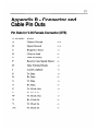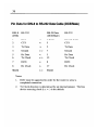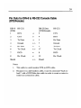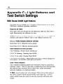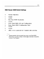
1
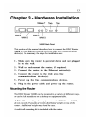
RISC Router 3400R
Installation Guide
Compatible Systems Corporation
4730 Walnut Street
Suite 102
Boulder, Colorado 80301
303-444-9532
800-356-0283
RISC Router 3400R Installation Guide, Version 1.1
Copyright(c) 1995, Compatible Systems Corporation
All rights reserved. RISC Router and RouterView are
trademarks of Compatible Systems Corporation. Other
trademarks are the property of their respective holders.
Part number: A00-0968
FCC Notice: This product has been certified to comply with
the limits for a Class À computing device, pursuant to Subpart J
of Part 15 of FCC Rules. It is designed to provide reasonable
protection against radio or television communication interference
in a commercial environment. Operation of this equipment in a
residential area could cause interference with radio or television
communication.
CHAPTER 1 - INTRODUCTION 7
ABOUT THE RISC ROUTER 3400R
Getting Started
Hardware Installation
RouterView Software Installation
Command Line Preparation
Quickstart Configuration
Appendices and Index
GO CO CO CO CO OO —]
CHAPTER 2 - GETTING STARTED
№
A FEW NOTES
Please Read The Manuals
Warranty and Service
Getting Help With the RISC Router 3400R
WHAT YOU WILL NEED TO GET STARTED
Supplied with the RISC Router 3400R
Needed For Installation
Ethernet Connection Requirements
Thick Ethernet
Thin Ethernet
10Base-T Twisted-Pair Ethernet
Telco Line Connection Requirements
ph pk fk jd fd fd = fd fd
N N == a — = = С С С © © © ©
V.35 Port
RS-232 Port
CHAPTER 3 - HARDWARE INSTALLATION 13
Mounting the Router 13
19” Rack Front Mount 14
19” Rack Center Mount 14
Wall Mount 14
Connecting the Router to the Ethernet 14
Connecting to Thick Ethernet 15
Connecting to Thin Ethernet 15
Connecting to Twisted-Pair Ethernet 15
Connecting a Line Device to the RISC Router 3400R 15
Connecting Devices to the V.35 Ports 15
Connecting Devices to the RS-232C Ports 16
Connecting an Out-of-Band Management Console 16
Powering Up the Router 17
CHAPTER 4 - ROUTERVIEW SOFTWARE
INSTALLATION 19
RouterView for Windows 19
System Requirements 19
Installing and Running RouterView for Windows20
RouterView for Macintosh 20
System Requirements 21
Installing and Running RouterView for Macintosh21
CHAPTER 5 - SETTING UP COMMAND LINE
MANAGEMENT 23
Out-of-Band Command-Line Management 23
Setting Up Telnet Operation 23
CHAPTER 6 - QUICKSTART INSTRUCTIONS 25
ETHERNET PORT CONFIGURATION 25
IP Protocol 26
Required for IP 26
Suggested for IP 26
IPX Protocol 26
Required for IPX 26
Suggested for IPX 27
Apple Talk Protocol 27
Required for AppleTalk 27
Suggested for AppleTalk 27
DECnet Protocol 27
Required for DECnet 27
Suggested for DECnet 28
WAN PORT PPP CONFIGURATION 28
IP Protocol 28
Required for IP 28
Suggested for IP 28
IPX Protocol 29
Required for IPX 29
Suggested for IPX 29
Apple Talk Protocol 29
Required for AppleTalk 29
Suggested for AppleTalk
DECnet Protocol
Required for DECnet
Link Configuration
Required for Dedicated/Leased Line Operation 30
Suggested for Dedicated/Leased Line Operation30
Required for Dial-On-Demand Operation
Suggested for Dial-On-Demand Operation
Physical Comm Settings
WAN PORT FRAME RELAY CONFIGURATION
IP Protocol
Required for IP
Suggested for IP
IPX Protocol
Required for IPX
Suggested for IPX
Apple Talk Protocol
Required for AppleTalk
Suggested for AppleTalk
DECnet Protocol
Required for DECnet
Link Configuration
30
Suggested for Dedicated/Leased Line Operation 34
Frame Relay DLCT Mappings 34
Physical Comm Settings 34
APPENDIX A - SHIPPING DEFAULTS 35
Ethernet Port 35
IP Defaults 35
IPX Defaults 35
AppleTalk Defaults 35
DECnet Defaults 35
WAN Port 35
IP Defaults 35
IPX Defaults 36
AppleTalk Defaults 36
DECnet Defaults 36
V.35 (WAN A & WAN B) Link & Physical
Defaults 36
RS-232 (WAN C & WAN D) Link & Physical
Defaults 36
APPENDIX B - CONNECTOR AND CABLE PIN OUTS 37
Pin Outs for V.35 Female Connector (DTE) 37
Pin Outs for DIN-8 to RS-232 Data Cable (DCE/Male)38
Pin Outs for DIN-8 to RS-232 Console Cable
(DTE/Female) 39
APPENDIX C - LIGHT PATTERNS AND TEST SWITCH
SETTINGS 40
RISC Router 3400R Light Patterns 40
Power On, No Traffic 40
Ethernet Traffic Indicators (Ethernet LED Bar)40
Other Indicators (on Both LED Bars) 40
Level 1 Panic Indicators 40
RISC Router 3400R Switch Settings 41
APPENDIX D - DOWNLOADING SOFTWARE FROM
COMPATIBLE SYSTEMS 42
The Compatible Systems FTP Server 42
CompuServe 42
Bulletin Board 43
AppleTalk Remote Access Server 43
APPENDIX E - TERMS AND CONDITIONS 44
Chapter 1 - Introduction
About the RISC Router 3400R
Congratulations on your purchase of the RISC Router 3400R
multiport wide area router. The RISC Router 3400R supports the IP,
IPX, AppleTalk, and DECnet protocols, with dial-on-demand and
leased-line operation using the PPP and/or the Frame Relay wide area
protocols.
This manual will help you install the RISC Router 3400R to connect
your local Ethernet to one or more wide area networks. These networks
may be connected to other Compatible Systems routers, or to routers
from other vendors. You can also use the RISC Router 3400R (or one
of its WAN ports) to connect your network to an Internet Service
Provider.
In short, the installation steps are:
1. Install the RISC Router hardware and connect it to one or more
line communication devices (including modems, 56K CSU/DSU's,
ISDN Terminal Adapters, or T1/E1 CSU/DSU’s).
2. Select the management method you wish to use with the router.
If you want to use the RouterView management software, you
must install the software on a Windows PC or Macintosh
computer which is connected to your network.
3. Configure the RISC Router LAN and WAN parameters using
the management method you have chosen.
If you have any difficulties during the installation or use of the RISC
Router that are not answered by this guide, please call Compatible
Systems Corporation or your RISC Router 3400R reseller.
Compatible Systems' phone number is listed on the front of this guide.
We will be happy to help you.
The manual is divided into several sections that should provide you
with all the information you will need to use the RISC Router 3400R
on your network.
Getting Started
This part of the manual describes the contents of the RISC Router
3400R package and emphasizes the preparation and equipment you will
need to install the router.
Hardware Installation
Here you will find step-by-step instructions on how to physically
install the RISC Router 3400R and connect it to your local Ethernet
and your wide area network(s). Instructions are included for thick, thin,
and twisted-pair Ethernet environments as well as modems, S6K &
T1/E1 CSU/DSUs, and ISDN terminal adapters.
RouterView Software Installation
If you plan to use RouterView, Compatible Systems’ GUI (Graphical
User Interface) management software which is included with your
router, then read this section. Instructions are provided on how to
install RouterView for Windows or Macintosh environments.
Command Line Preparation
If you have decided to use command line management, either out-of-
band (through the AUX port), or in-band through Telnet, read this
section,
Quickstart Configuration
The Quickstart section provides a list of parameters that must be
entered into a router for proper operation.
Appendices and Index
Additional information that might be of interest to you such as
technical specifications and a quick reference to specific information can
be found at the end of this guide.
Chapter 2 - Getting Started
A Few Notes
Please Read The Manuals
The manuals included with your RISC Router 3400R contain some
very important information about the RISC Router 3400R and local
and wide area networking in general. Please read this manual
thoroughly, and refer to the management reference guides as required.
It’s worth the few minutes it will take.
Also, please fill out the warranty registration card and return it to us
today. This will help us keep you informed of updates to the RISC
Router 3400R and future products available from Compatible Systems.
Warranty and Service
The RISC Router 3400R is covered by the Compatible Systems
Integrated Support Package, which includes a three-year comprehensive
warranty, a twenty-four hour advanced replacement program, unlimited
phone support, and software upgrades for the life of the product.
Compatible Systems maintains copies of current software updates on
the Internet, CompuServe, AppleLink, an ARA server, and a bulletin
board. You may download product software from any of these sources
at any time. For more information on downloading current product
software, see the appendices for this manual.
Getting Help With the RISC Router 3400R
If you have a question about the RISC Router 3400R and can’t find the
answer in this manual, feel free to call our technical support department
at (800) 356-0283. You may also send support questions via e-mail to
support e Compatible. COM.
10
What You Will Need To Get Started
Before connecting the RISC Router 3400R, please check the list below
to make sure that you have received all of the items that are supplied
with the RISC Router 3400R package.
You should also make sure you have any additional items that are
necessary to connect the router to your network.
Supplied with the RISC Router 3400R
Please check your shipping package for the following items:
RISC Router 3400R unit
Rack-mount kit
e Power cord
* Two DIN-8 to DB-25 data cables
* One DIN-8 to DB-25 auxiliary port cable
* Windows RouterView diskette
Macintosh RouterView diskette
*. Windows download software diskette
* Macintosh download software diskette
RouterView reference guide
* Command line reference guide
* Warranty registration card
* Note. Some routers may be shipped with three RS-232 “Y” cables.
These cables can be used for both data and auxiliary port operation.
Needed For Installation
Before connecting the RISC Router 3400R to your network, you need
to make sure that you have the necessary equipment for connecting to
the local Ethernet and the wide area transmission device(s) (modem,
56K CSU/DSU, ISDN terminal adapter, T1 CSU/DSU).
11
Ethernet Connection Requirements
The RISC Router 3400R’s Ethernet port directly supports thick, thin
and 10BaseT twisted-pair Ethernet. Switching among the three ports is
automatic — simply plug the proper Ethernet connector into its port.
Other Ethernet cabling types (such as fiber optic cabling or pre-
10BaseT twisted-pair) can be supported using adapters which connect to
a thick Ethernet port.
Thick Ethernet
To connect the router's Ethernet port to a standard (thick) Ethernet cable
you will need a transceiver cable connection at the correct location on
your Ethernet cable. The transceiver cable will attach directly to the
DB-15 connector on the router.
Thin Ethernet
To connect the router's Ethernet port to a thin Ethernet cable you will
need a T-connector installed at the correct location on your Ethernet
cable. A T-connector is required for proper termination of the cable.
10Base-T Twisted-Pair Ethernet
To connect the router's Ethernet port to twisted-pair Ethernet cabling
you will need an unshielded twisted-pair wire that is connected to a
10BaseT-compatible twisted-pair hub.
* Note: Ethernet cables and cable connectors are not supplied with the
RISC Router product. Please contact your reseller or your Compatible
Systems representative for information on obtaining the correct
Ethernet cabling supplies.
“* Note: These hardware installation instructions assume that your
Ethernet cabling is already in place. Thin coaxial Ethernet network
cabling should be terminated at each end with 50 Ohm terminator
plugs. A T-connector or transceiver must be available in the location
where you will be installing the router.
Telco Line Connection Requirements
The RISC Router 3400R 1s not a line communications device. In order
to connect to a wide area transmission line, you must use a modem,
12
56K CSU/DSU, ISDN Terminal Adapter, or T1/E1 CSU/DSU. Which
of these devices you use depends on the type of line you are connecting
to, along with which port on the RISC Router you plan to use for the
specific connection.
*» Note: Before attempting to connect the RISC Router 3400R to a
leased telco line, use the loopback features of your CSU/DSU's to
check the line. This can save you a considerable amount of time, since
the more equipment you have on the line, the more difficult it becomes
to determine where a problem is occurring.
The RISC Router 3400R provides two primary synchronous V.35
ports, which are capable of running at rates up to T1/E1 (2 megabits
per second). Two secondary RS-232 sync/async ports are also provided.
V.35 Port
The RISC Router 3400R does not include V.35 cables. These cables
are available from your reseller, or a number of other suppliers. The
RISC Router 3400R has female V.35 connectors, as do virtually all
line communications devices. Thus, the V.35 cable required to connect
to a line communications device will usually have male connectors at
both ends.
RS-232 Port
The RISC Router 3400R includes two DIN-8 to DB-25 RS-232
sync/async data cables. These cables support RS-232 asynchronous
modems, synchronous leased and switched-56K CSU/DSU’s, and North
American ISDN Terminal Adapters.
Some Japanese and European terminal adapters may require an adapter
plug. For more information, contact Compatible Systems.
* Note: Please use only these cables when connecting your line
communication device to the RISC Router 3400R. The cables
provided with other equipment do not provide all of the connections
required between connector pins for correct hardware handshaking and
synchronous clocking.
13
Chapter 3 - Hardware Installation
10Base T Thick Thin
x +
ne Je 9 00 = © |
7 ‘
WAN A / WAN C \
WAN B WAN D
3400R Back Panel
This section of the manual describes how to connect the RISC Router
3400R to your Ethernet network and your wide area communications
device(s). In summary, the steps for installation are:
1. Make sure the router is powered down and not plugged
in to the wall.
2. Wall or rack-mount the router, if required.
3. Connect the router to the Ethernet network(s).
4. Connect the router to the wide area line
communications device(s).
5. Power up the line communications devices.
Plug in the power cable and power up the router.
Mounting the Router
The RISC Router 3400R can be mounted in a variety of different ways,
or can be left standalone on a desktop or equipment table.
» Note: When stacking other equipment on the RISC Router 3400R,
do not exceed 25 pounds of evenly distributed weight on top of the
router. Additional weight may bend the case.
A rack/wall mounting kit is included with the router.
14
19” Rack Front Mount
Install the rack-mount ears on the sides of the case towards the front,
using the screws provided. Position the ears so that they are flush with
the front of the case. The slotted holes in the ears will mate with the
mounting holes in a standard 19” rack.
“ Note: The RISC Router 3400R is 1U high when its bottom-mounted
rubber feet are removed. If you intend to mount the unit in a 1U space,
make sure your equipment rack is well ventilated. Otherwise, thermal
problems may occur.
19” Rack Center Mount
Install the rack-mount ears using the mounting holes midway along the
sides of the case, using the screws provided. The slotted holes in the
ears will mate with the mounting holes in a standard 19” rack.
Wall Mount
Install the rack-mount ears on the middle of the case, using the screws
provided. Position the ears so that they are flush with the bottom of
the case. The slotted holes in the ears will mate with wood screws or
other attachment methods.
*» Note: Wood screws are not provided with the rack-mount kit.
Connecting the Router to the Ethernet
For thick and thin Ethernet networks you should have installed your
Ethernet cabling before you install the RISC Router 3400R.
If you have a coax installation, the Ethernet network cable should be
terminated at both ends with 50 Ohm network terminating resistors,
and a T-connector or transceiver should be available at the location
where you will connect the router.
If you are installing a twisted-pair connection, and the twisted-pair hub
is already in place, or a T-connector or thicknet transceiver is already
installed on your Ethernet cable, you can connect the router to an active
network without interrupting network activity.
The RISC Router 3400R's Ethernet interface features all three media
connector types. The active media connection will automatically be
selected when you attach a cable.
15
Do not terminate inactive connectors on the router, as
this may cause an incorrect media type to be selected.
Connecting to Thick Ethernet
To connect the router to a thick Ethernet network, simply plug one end
of a transceiver cable into the DB-15 transceiver connector located on
the back panel of the unit. Then, plug the other end of the transceiver
cable into the transceiver which should already be attached to the thick
Ethernet cable.
Connecting to Thin Ethernet
In order to connect the router to a thin Ethernet cable, connect a T-
connector to the BNC connector located on the rear panel of the unit.
Connecting to Twisted-Pair Ethernet
Before connecting the router to twisted-pair cabling you need an
unshielded twisted-pair cable that is already connected to your 10BaseT-
compatible twisted-pair hub.
To connect the router to the twisted-pair network, simply plug the
twisted-pair cable into the RJ-45 connector on the back of the unit.
Connecting a Line Device to the RISC Router 3400R
The RISC Router 3400R supports high-speed synchronous operation
over two V.35 connectors. It also supports lower speed
synchronous/asynchronous operation over two RS-232 connectors.
The RISC Router 3400R supports both PPP and Frame Relay link
protocols on all WAN ports.
Connecting Devices to the V.35 Ports
These ports -- WAN A(0) and WAN B(1) -- can be used to connect to a
wide variety of line communications devices, including those which
support either leased or dialed operation.
Examples include leased S6K CSU/DSU’s, switched 56K CSU/DSU’s,
fractional T1 CSU/DSU’s, ISDN terminal adapters, and full T1/E1 rate
CSU/DSU?s.
16
You may select either dial-on demand, redial if down (“always up”
mode), or leased line operation. These ports may also be set to receive
ISDN or switched-56 incoming calls.
To connect a device, first make sure that both units are powered off.
Then, simply connect a V.35 cable (not supplied) between the router
and the device.
Connecting Devices to the RS-232C Ports
These ports -- WAN C(2) and WAN D(3) -- can be used to connect to
synchronous or asynchronous line communications devices at rates up
to 128Kbps (115.2 Kbps async).
Examples include modems, leased or switched S6K CSU/DSU’s, and
ISDN terminal adapters.
You may select either dial-on demand, redial if down (“always up”
mode), or leased line operation. These ports may also be set to receive
ISDN or switched-56 incoming calls.
To connect a device, first make sure that both units are powered off.
Then, simply connect one of the supplied RS-232 data cables (not an
auxiliary port cable) between the router and the device.
* Note: The RISC Router 3400R RS-232 ports require that your line
communications device be set to supply the RS-232 DCD signal when
a connection has been made..
« Note: The RISC Router 3400R includes two special data cables to
facilitate connections to RS-232 line communications devices. These
cables include support for several asynchronous and synchronous
control signals. Off-the-shelf Sun or Macintosh-type cables do not
support these signals.
Connecting an Out-of-Band Management Console
If you wish to connect an out-of-band management console, use the
supplied auxiliary cable and connect to the AUX port on the front of
the RISC Router 3400R. You can use a dumb terminal or a computer
equipped with VT100 terminal emulation.
The default baud rate for the AUX port is 9600.
17
Powering Up the Router
Power up all modems, CSU/DSU’s, and TA’s before powering up the
router. This allows the router to immediately sense which of its ports
are connected. At power-up, the router will take approximately one
minute to become visible to RouterView.
* Note: If you want to use Telnet as a management method, you must
configure an IP address into the router using an out-of-band console or
RouterView before you will be able to contact the router.
19
Chapter 4 - RouterView Software
Installation
All of the routers in Compatible Systems’ multiprotocol family,
including all MicroRouter and RISC Router models, can be managed
from a single management platform called RouterView. Both a
Windows and a Macintosh version of RouterView were included with
your RISC Router 3400R.
* Note: Although the installation procedures for the Windows and
Macintosh versions of RouterView are slightly different, the programs
themselves are virtually identical. Once you have installed RouterView
on the platform of your choice, you can find more information on how
to use it in the RouterView Reference Guide which was included with
your router.
RouterView for Windows
RouterView for Windows allows you to manage the RISC Router
3400R from an IBM-compatible PC running Windows. The PC can
elther be configured as an IPX ODI client on a Novell NetWare
internet, or as an IP WinSock client on an IP internet.
System Requirements
In order to successfully run RouterView for Windows, you need:
« IBM PC or compatible w/ 386 or later processor
* Windows 3.1 or Windows for Workgroups installed
* VGA or better monitor
And either (or both) of:
Novell IPX client configuration on a NetWare network, using
IPXODI.COM
* WinSock client configuration on an IP network
* Note: The “IPX 101” appendix to the RouterView Reference Guide
contains some tips on getting Novell’s IPX ODI running on your
client machine.
20
* Note: To force a Windows machine which has both IPX and IP
installed to use IP, you must insert the statement LoadIPX = 0 in the
[Settings] section of your C?>XWINDOWSWOUTVIEW.INT file.
Installing and Running RouterView for Windows
This version of the RouterView program can be found on a 3.5-inch
diskette labeled "RouterView - Windows Disk" that was included with
your RISC Router 3400R.
Start Windows. Insert the diskette into your computer's disk drive. At
the Windows Program Manager, select "Run" from the File menu and
type A:SETUP (where A: 1s the drive containing the RouterView
diskette). This will invoke an auto-installation program supplied with
RouterView.
The installation program will ask you to select (or create) a directory in
which it should locate RouterView and its associated files and database
subdirectory.
Once the installation is complete, double click on the RouterView icon
to open the program. For further information on using RouterView,
see the RouterView Reference Guide included with your router.
* Note. RouterView will be able to use the transport protocol (IP or
IPX) you have selected to access Compatible Systems routers anywhere
on your internetwork. This means you can use the IP transport option
to manage routers across the global Internet network if you are
connected to it.
* Note: For an up-to-date description of the changes (if any) made to
Windows system files by the installation program, see the
README.TXT file located in the RouterView installation directory.
RouterView for Macintosh
RouterView for Macintosh allows you to manage the RISC Router
3400R from an Apple Macintosh or compatible computer.
RouterView for Macintosh uses the Apple Talk protocol to
communicate with the router.
21
System Requirements
A Macintosh version of RouterView was included with your router.
You can run RouterView from any Macintosh on your network that
meets the following technical specifications:
* Macintosh with 68030 or later processor (including PowerPC)
* System 7.0 or later.
* Note: Although older Macintoshes such as SE/30’s and Hsi’s will
run RouterView adequately for infrequent use, a newer/faster machine is
preferable for larger networks where RouterView will be used more
often.
Installing and Running RouterView for Macintosh
To install RouterView for Macintosh, simply insert the RouterView
diskette into the floppy drive of your Macintosh. Then double click on
the self extracting archive (.sea) icon. You will be asked where you
would like to locate your copy of the RouterView program and data
files.
Double-click on the RouterView icon and the program will start up and
ask you to select/create a location for its database. Once the database
has been created, this message will not reappear when you run
RouterView.
For further information on using RouterView, see the RouterView
Reference Guide included with your router.
23
Chapter 5 - Setting Up
Command Line Management
The command-line interface allows you to configure and monitor the
router in-band via Telnet or out-of-band with a terminal connected to
the RISC Router 3400R’s AUX port.
Telnet 1s a remote terminal communications protocol based on TCP/IP.
With Telnet you can log into and manage the router from anywhere on
your IP internetwork, even across the global Internet 1f you choose. To
do this, you must run Telnet client software on your local computer,
which will communicate with the Telnet server built into the router.
In order to be able to access the command-line interface via Telnet, you
must first set some IP parameters in the router. You can do this
through the AUX port using a terminal or a PC with terminal
emulation software, or with RouterView if you prefer.
After the IP parameters are set, you can complete the configuration in-
band with Telnet.
Out-of-Band Command-Line Management
Set a terminal or a PC to a baud rate of 9600, and connect it to the
router's AUX port using the auxiliary cable which was supplied with
the router. Press the <Return> key three or four times.
Enter the default password letmein at the password prompt. The
command line interface prompt will appear on the screen.
For further information on using the command line interface, see the
Command Line Reference Guide that was supplied with your router.
Setting Up Telnet Operation
Before being able to access the command line interface via Telnet, you
will need to complete basic IP configuration for the port which you
will connect through.
24
This can be done using the set ip commands from a console. For
more information on these commands, see the Command Line
Reference Guide which was supplied with your router.
The required parameters for Telnet operation are the IP address, IP
subnet mask, and IP broadcast address. To change the configuration
parameters in the RISC Router 3400R, you will have to enter a
requested password. The default password is letmein.
After you have set these basic IP parameters, you can use Telnet to
access the router from any node on your IP internetwork. Invoke the
Telnet client on your local computer with the IP address of the router
you wish to manage.
** Note: Proper syntax is vital to effective operation of the command
line. Case is not significant — you may enter commands in upper case,
lower case, or a combination of the two.
25
Chapter 6 - Quickstart
Instructions
This Quickstart section briefly discusses the major parameters that
must be set in order to use the router.
There are a number of parameter settings which are optional, in the
sense that they are not required for all installations. These settings are
not covered in this section.
In this section:
RV = RouterView
CL = Command Line
*» Note: Considerably more information on the meaning of the router's
parameters is provided in the RouterView Reference Guide and the
Command Line Reference Guide. You should use this list as a starting
point to look up more specific information in the other documents. If
you need more general information on the protocols, see the
Appendices in the RouterView Reference Guide.
*» Note: If you are using the RISC Router 3400R to connect to an
Internet Service Provider (ISP), you will receive your configuration
parameters from the technical staff of the ISP. These parameters must
include all IP addresses, WAN settings, and any applicable
authorization routines. If you obtained your RISC Router 3400R
directly from an ISP, it may be pre-configured for your site.
Please check with your ISP before configuring or changing the
configuration of your RISC Router 3400R.
Ethernet Port Configuration
Ethernet ports are considerably easier to set up than wide area ports
since there are no choices that need to be made regarding line
communications devices and their parameters. We recommend that you
begin by configuring any Ethernet port parameters before proceeding to
configure WAN port parameters.
26
IP Protocol
Required for IP
These parameters set the basic address characteristics of the port. They
provide enough information for another IP node to find the port (such
as a Telnet client), but not enough information for routing to take
place.
* IP Address
IP Subnet Mask
* IP Broadcast Address
RV: Use the Ethernet/IP screen to set these parameters.
CL: Use the interface(misc) and ip(set) commands.
Suggested for IP
These parameters help supply information about the segment that the
port is connected to. With this information, routing can take place.
IP RIP (Routing Information Protocol)
and/or
* IP Static Routes
RV: Use the Ethernet/IP screen to set RIP, and the IP Static Routing
Window (AlVIP) to set static routes.
CL: Use interface(misc) and ip flags(set) to set RIP, and ip
route(add) to add static routes.
IPX Protocol
Required for IPX
There are generally no required changes from the shipping Ethernet
configuration for IPX. The Ethernet port will autoconfigure to use the
two most common IPX frame types, and will autoadapt to conditions
on the Ethernet.
27
Suggested for IPX
You may want to set your own network numbers, rather than using the
autoconfigured values. You may also want to turn off unused frame
types.
RV: Use the Ethernet/IPX screen.
CL: Use interface(misc) and ipx(set).
AppleTalk Protocol
Required for AppleTalk
There are generally no required changes from the shipping Ethernet
configuration for AppleTalk. The Ethernet port will autoconfigure to
use AppleTalk Phase II, and will autoadapt to conditions on the
Ethernet.
Suggested for AppleTalk
You may want to set your own network numbers, rather than using the
autoconfigured values. You may also want to use more meaningful
zone names.
КУ: Use the Ethernet/AppleTalk screen.
CL: Use interface(misc) and appletalk(set).
DECnet Protocol
Required for DECnet
The router’s shipping configuration does not have DECnet turned on.
You must turn it on and set several DECnet parameters.
е Turn DECnet on
* Set DECnet area
* Set DECnet node
RV: Use the Main DECnet screen (AlV/DECnet).
CL: Use decnet(set).
28
Suggested for DECnet
Setting the parameters above should be adequate for most installations.
WAN Port PPP Configuration
This section covers the settings required for PPP (point-to-point)
protocol operation of the RISC Router 3400R WAN ports. In general,
the parameters listed here should be set for each WAN port on which
you plan to use PPP.
There are a few differences between the capabilities of the V.35 WAN
ports and the RS-232 WAN ports. The V.35 ports can only be run
synchronously, at rates up to 2 Mbps per second. The RS-232 ports
can be run synchronously or asynchronously, at rates up to 128Kbps
(sync), or 115.2Kbps (async).
IP Protocol
Required for IP
WAN ports which are set for PPP operation do not generally use an IP
address. They are set to act as an “unnumbered interface.” In this mode
of operation, there are no required settings.
Suggested for IP
These parameters help supply information about the segment that the
port is connected to. With this information, routing can take place.
IP RIP (Routing Information Protocol)
and/or
* IP Static Routes
* IP Default Router
* Note: If you set RIP to on for a dial-on-demand link, you must also
set the update method to triggered to avoid the link being brought up
by transmission of RIP information.
RV: Use the WAN/IP screen to set RIP and the update method, and
the IP Static Routing Window (AIVIP) to set static routes and a default
router.
29
CL: Use interface(misc) and then ip flags(set) to set RIP, and ip
wan(set) to set the updated method, and ip route(add) to add static
routes. User interface(misc) and ip(set) to set the default router.
IPX Protocol
Required for IPX
WAN ports which are set for PPP operation do not generally use an
IPX address. They are set to act as an “unnumbered interface.” In this
mode of operation, there are no required settings.
Suggested for IPX
If you plan to use dial-on-demand for this link, you should set the
update method (to triggered) to avoid the link being brought up by
transmission of IPX RIP information.
Update Method
КУ: Use the WAN/IPX screen.
CL: Use interface(misc) and then ipx wan(set).
AppleTalk Protocol
Required for AppleTalk
WAN ports which are set for PPP operation do not generally use an
AppleTalk address. They are set to act as an “unnumbered interface.”
In this mode of operation, there are no required settings.
Suggested for AppleTalk
If you plan to use dial-on-demand for this link, you should set the
update method (to triggered) to avoid the link being brought up by
transmission of AppleTalk RTMP information.
Update Method
RV: Use the WAN/AppleTalk screen.
CL: Use interface(misc) and then appletalk wan(set).
30
DECnet Protocol
Required for DECnet
WAN ports which are set for PPP dial-on-demand operation should
have their DECnet hello timers and DECnet routing timers set for a
fairly long period, since the link will be brought up when this
information is transmitted.
e Hello timer
Routing timer
RV: Use the WAN/DECnet screen.
CL: Use interface(misc) and then decnet wan(set).
Link Configuration
Required for Dedicated/Leased Line Operation
Dedicated line operation is the simplest to set up.
о Set Dedicated connection
Set PPP connection
RV: Use the WAN/Link screen.
CL: Use interface(misc) and then wan connect(set).
Suggested for Dedicated/Leased Line Operation
Dedicated line operation generally does not require additional parameters
for operation.
Required for Dial-On-Demand Operation
Incoming dial-on-demand operation requires only slightly more
information than dedicated line setup. Outgoing dial-on--demand
requires additional information (see the suggested settings below).
* Set dial-up connection
Set PPP connection
о Set to allow dial-in and/or dial-out
RV: Use the WAN/Link screen.
31
CL: Use interface(misc) and then wan connect(set).
Suggested for Dial-On-Demand Operation
Outgoing dial-on--demand requires some additional information.
* Set dialing method
* Create dial-out script
* Set dial-out script to be used
RV: Use the WAN/Link window to set the dialing method and to
select a chat script (once you have created one). Use the Chat Script
Editor window (All/Link) to create your chat script.
CL: Use interface(misc) and then wan connect(set) to set the
dialing method and to select a chat script (once you have created one).
Use the chat(edit) command to create a chat script.
Physical Comm Settings
You may need to set the baud rate, sync/async operation, and other
physical communications parameters for the WAN port. These
parameters will depend on the line communications device you are
using.
RY: Use the WAN/General window.
CL: Use interface(misc) and then wan serial(set).
WAN Port Frame Relay Configuration
This section covers the settings required for Frame Relay operation of
the RISC Router 3400R WAN ports. In general, the parameters listed
here should be set for each WAN port on which you plan to use Frame
Relay.
There are a few differences between the capabilities of the V.35 WAN
ports and the RS-232 WAN ports. The V.35 ports can only be run
synchronously, at rates up to 2 Mbps per second. The RS-232 ports
can be run synchronously or asynchronously, at rates up to 128Kbps
(sync), or 115.2Kbps (async).
32
IP Protocol
Required for IP
Frame Relay operation requires that the WAN port is set to be a
“numbered interface.” This means that the port (and thus the Frame
Relay network) must have an IP address, etc.
о IP numbered interface
* IP Address
IP Subnet mask
* IP Broadcast Address
RV: Use the WAN/IP screen to set these parameters.
CL: Use the interface(misc) and ip wan(set) commands.
Suggested for IP
These parameters help supply information about the segment that the
port is connected to. With this information, routing can take place.
IP RIP (Routing Information Protocol)
and/or
* IP Static Routes
* IP Default Router
RV: Use the WAN/IP screen to set RIP, and the IP Static Routing
Window (AlVTP) to set static routes and a default router.
CL: Use interface(misc) and then ip flags(set) to set RIP, and ip
route(add) to add static routes. User interface(misc) and ip(set) to
set the default router.
IPX Protocol
Required for IPX
Frame Relay operation requires that the WAN port is set to be a
“numbered interface.” This means that the port (and thus the Frame
Relay network) must have an IPX network number.
e JPX numbered interface
33
e JPX Network Number
RV: Use the WAN/IPX screen.
CL: Use interface(misc) and then ipx wan(set).
Suggested for IPX
The settings above are all that is generally required for IPX operation
over Frame Relay.
AppleTalk Protocol
Required for AppleTalk
Frame Relay operation requires that the WAN port is set to be a
“numbered interface.” This means that the port (and thus the Frame
Relay network) must have an AppleTalk network number and the port
must have an AppleTalk node number.
AppleTalk numbered interface
AppleTalk Network Number
AppleTalk Node Number
RV: Use the WAN/AppleTalk screen.
CL: Use interface(misc) and then appletalk wan(set).
Suggested for AppleTalk
The settings above are all that is generally required for AppleTalk
operation over Frame Relay.
DECnet Protocol
Required for DECnet
Once DECnet has been turned on (a global setting discussed in the
Ethernet section above), no additional settings are generally required for
DECnet operation over Frame Relay.
34
Link Configuration
Frame Relay is presently supported in the RISC Router 3400R only
via dedicated line operation.
e Set Dedicated connection
* Set Frame Relay connection
RV: Use the WAN/Link screen.
CL: Use interface(misc) and then wan connect(set).
Suggested for Dedicated/Leased Line Operation
Dedicated line operation generally does not require additional parameters
for operation.
Frame Relay DLCI Mappings
If you are connecting to another Compatible Systems router, this
information 1s not required. Compatible Systems uses TARP (Inverse
Address Resolution Protocol) to dynamically generate this information.
To connect to other vendors” routers which do not support TARP, or do
not have it turned on, you must provide DLCI to protocol mapping
information.
КУ: Use the DLCI Mapping Database window.
CL: Use interface(misc) and then frelay(set).
Physical Comm Settings
You may need to set the baud rate, sync/async operation, and other
physical communications parameters for the WAN port. These
parameters will depend on the line communications device you are
using.
RY: Use the WAN/General window.
CL: Use interface(misc) and then wan serial(set).
35
Appendix A - Shipping Defaults
Ethernet Port
IP Defaults
e On
Address: 198.41.12.1
Subnet Mask: 255.255.255.0
Broadcast Address: 198.41.12.255
IP RIP off
IPX Defaults
802.3 on, autoseeding
802.2 on, autoseeding
* Type I off
802.2 SNAP off
AppleTalk Defaults
e Phase I off
Phase II on, autoseeding
DECnet Defaults
e Off
WAN Port
IP Defaults
e On
e Unnumbered interface
e RIP off
Van Jacobson compression off
36
IPX Defaults
* On
Unnumbered interface
AppleTalk Defaults
* On
Unnumbered interface
DECnet Defaults
. Off
V.35 (WAN A & WAN B) Link & Physical Defaults
PPP
* Dedicated
* Sync, external clock
RS-232 (WAN C & WAN D) Link & Physical Defaults
PPP
Dial-in
* Async @ 115.2Kbps
e Hardware flow control
37
Appendix B - Connector and
Cable Pin Outs
Pin Outs for V.35 Female Connector (DTE)
V.35 (DTE) Signal
ze ME <A mm UN >
Chassis Ground
Signal Ground
Request to Send
Clear to Send
Data Set Ready
Receive Line Signal Detect
Data Terminal Ready
Local Loopback
Tx Data
Rx Data
Tx Data
Rx Data
Tx Clock Out
Rx Clock In
Tx Clock Out
Rx Clock In
Tx Clock In
Tx Clock In
<->
<->
AAA бу бу бу у у ^^^
38
Pin Outs for DIN-8 to RS-232 Data Cable (DCE/Male)
DIN-8 RS-232
(DTE)
1 RTS
2 CTS
3 Tx Data
4 Ground
5 Rx Data
6 Tx Clock
7 DCD
8 Rx Clock
Shield
Notes:
DB-25 Data RS-232
(DCE/Male)
4 & 20 RTS & DTR
5 CTS
2 Tx Data
7 Ground
3 Rx Data
15 Tx Clock
8 DCD
17 Rx Clock
Shield
1. DCD must be supported in order for the router to sense a
completed connection.
2. Tx Clock direction is determined by an internal jumper. The line
device sourcing clock (i.e. <- ) is the default.
39
Pin Outs for DIN-8 to RS-232 Console Cable
(DTE/Female)
DIN-8 RS-232
(DTE)
RTS
CTS
Tx Data
Ground
Rx Data
Tx Clock
DCD
Rx Clock
0 41 ON E WN =
Shield
Notes:
DB-25 Data RS-232
(DTE/Female)
5 CTS
4 RTS
3 Rx Data
7 Ground
2 Tx Data
17 Tx Clock
8 DCD
15 Rx Clock
Shield
1. This cable is a null-modem DTE-to-DTE cable.
2. Because it is a null-modem cable, it can be connected “back-to-
back” with a DCE/Male data cable in order to create a router-to-
router test connection cable.
40
Appendix C - Light Patterns and
Test Switch Settings
RISC Router 3400R Light Patterns
The RISC Router 3400R uses a number of light patterns on its front
LED bars to indicate operating conditions.
Power On, No Traffic
The router will scan through the left (Ethernet) LED bar, from left to
right, illuminating one element at a time.
* Note: Lights ! and 10 are directly connected to the router’s 10BaseT
interface and indicate 10BaseT link (1) and 10BaseT polarity (10).
Ethernet Traffic Indicators (Ethernet LED Bar)
Scan from 2 to 5: Ethernet receive packet
Scan from 9 to 6: Ethernet transmit packet
Other Indicators (on Both LED Bars)
5 & 6 flashing: Router stacks starting up
3,4 & 7,8 flashing: Running from ROM
3,5 & 7,9 on solid: Erasing Flash ROM
2 to 4 & 9 to 6 rotating: Flash ROM erase due to switch setting five
1s complete. Set switch to zero and cycle power.
Level 1 Panic Indicators
Any continuous flashing pattern not noted above may be caused by a
software “panic.” This is a sign that a condition has been detected that
the software does not know how to deal with: either an unusual
network condition, or a hardware failure.
* Note: Level 1 panics are very unusual. These are not the same as
the Level 2 panics which may be noted in the router log. Level 2
panics simply cause the router to save the reason for the panic and
restart.
41
RISC Router 3400R Switch Settings
0 Normal Operation
1 Unused*
2 Unused*
3 Run Boot ROM Downloader
4 Unused*
5 Erase Flash ROM (OS and Configuration)
6 Erase Flash ROM (Configuration Only)
7 Unused*
8 Unused*
9
Allow letmein password for 5 minutes after powerup
Notes:
1. Settings marked with an asterisk may erase your Flash ROM.
Please don’t use these settings without first contacting Compatible
Systems Tech Support.
42
Appendix D - Downloading
Software From Compatible
Systems
We make the latest versions of operating software for all Compatible
Systems products available from a number of on-line sources. The
latest versions of RouterView management software 1s also available at
these locations.
To download software, select the proper source and follow the
instructions below.
The Compatible Systems FTP Server
The FTP Server is accessible via the Internet. If your company does
not have an Internet account, check the other sources.
1. FTP to ftp.Compatible. COM and login as “anonymous.” Change
the working directory to Compatible (cd Compatible). List the
available directories (Is). Change the working directory to the
appropriate directory (e.g. RISCRouter).
2. To transfer the files from the FTP, type “get” followed by the
filename.
3. Disconnect from the FTP server.
* Note: Uncompressed downloads (suitable for TFTP and RouterView
Windows downloading) are stored as .dld files. Self-extracting
Windows compatible style files (and RouterView for Windows itself)
are stored as .exe files. Self extracting Macintosh style files are stored
as .sea.bin and/or .sea.hgx files.
* Note: These files are also accessible via the World Wide Web at
http://www.compatible.com
CompuServe
Compatible Systems maintains a software library in the LAN Vendors
Forum of the CompuServe on-line service. To access the software
library, follow these steps:
43
Type the GO COMPATIBLE command. This will place you in the
LAN Vendors Forum.
Compatible Systems may be found in section 12 of this forum.
Follow the instructions provided by CompuServe regarding
downloading files.
Bulletin Board
Compatible Systems administers a bulletin board that you can access
using standard telecommunications software. The bulletin board
supports modem settings of 8-N-1 and speeds up to 9600 KBps. The
BBS phone number is (303) 443-0845.
1.
2.
Type ‘bbs’ at the first login prompt.
Type “guest” at both the user and password query of the BBS login
prompt. At any time after you login, you may type ‘h’ and receive
a list of valid commands.
Once logged in, change to the files section of the BBS by using
the “F” command. Set the transfer protocol you wish to use
(Zmodem is default) using the “*P” command.
Select the appropriate sub-board according to product and download
the file(s) that you need via the ‘d’ command.
AppleTalk Remote Access Server
You can reach our AppleTalk Remote Access (ARA) server at (303)
444-8769. You must have Apple’s ARA software to access this server.
1.
2.
Log in to the server as a guest.
Choose the server named ‘Compatible ARA Server’ which is
located in the “DemoNet Zone” zone.
Open the appropriate folder and simply drag the file onto your hard
disk.
44
Appendix E - Terms and
Conditions
Compatible Systems Corporation (Compatible Systems) offers to sell only
on the condition that Customer’s acceptance is expressly limited to
Compatible Systems’ terms and conditions of sale. Compatible Systems’
acceptance of any order from Customer is expressly made conditional on
assent to these terms and conditions of sale unless otherwise specifically
agreed to in writing by Compatible Systems. In the absence of such
agreement, commencement of performance or delivery shall be for
Customer’s convenience only and shall not be construed as an acceptance of
Compatible Systems’ terms and conditions. If a contract is not earlier
formed by mutual agreement in writing, Customer’s acceptance of any
goods or services shall be deemed acceptance of the terms and conditions
stated herein.
1. Warranty. Compatible Systems warrants to the Customer and to all
persons who purchase Products from the Customer during the Warranty
terms (“subsequent purchasers”), that, for a period of three (3) years from the
date (the “shipping date”) on which Compatible Systems ships the Products
to the Customer: (a) the Product meets, in all material respects, all
specifications published by Compatible Systems for such Products as of the
shipping date; (b) the Products are free from all material defects in materials
and workmanship under normal use and service; and (c) that as a result of
the purchase of the Products from Compatible Systems, the Customer will
have good title to the Products, free and clear of all liens and encumbrances.
Compatible Systems’ obligations pursuant to this Warranty, and the sole
remedies of the Customer and of any subsequent purchaser, shall be limited
to the repair or replacement, in Compatible Systems’ sole discretion, of any
of the Products that do not conform to this Warranty.
This Warranty shall be invalidated if the Products (a) have not been
installed, handled, or used in accordance with Compatible Systems
recommended procedures; (b) have been damaged through the negligence or
abuse of the Customer or of any subsequent purchasers; (c¢) are damaged by
causes external to the Products, including (without limitation) shipping
damage, power or air conditioning failure, or accident or catastrophe of any
45
nature; and (d) have been subjected to repairs or attempted repairs by any
person other than Compatible Systems (or an authorized Compatible
Systems service technician).
To obtain service under this Warranty, the Customer (or subsequent
purchaser, if applicable) must follow the procedures outlined below, under
“Product Return Policy.”
THE WARRANTIES SET FORTH IN THESE TERMS AND
CONDITIONS ARE IN LIEU OF ALL OTHER WARRANTIES,
EXPRESSED OR IMPLIED. WITHOUT LIMITATION ON THE
GENERALITY OF THE FOREGOING SENTENCE, COMPATIBLE
SYSTEMS EXPRESSLY DISCLAIMS AND EXCLUDES ALL
IMPLIED WARRANTIES OF MERCHANTIBILITY AND OF FITNESS
(GENERALLY OR FOR A PARTICULAR PURPOSE).
2. Shipments. All delivery indications are estimated and are dependent in
part upon prompt receipt of all necessary information to service an order.
Compatible Systems shall not be liable for any premium transportation or
other costs or losses incurred by Customer as a result of Compatible
Systems inability to deliver Product in accordance with Customer’s
requested delivery dates. All shipments by Compatible Systems are made
F.O.B. factory (Boulder, Colorado); risk of loss shall pass to Customer at
point of shipment. Unless specified by the Customer, Compatible Systems
will select the mode of transportation for each order. Compatible Systems
reserves the right to make deliveries in installments. Partial shipments are
subject to the terms of payment noted below. Compatible Systems reserves
the right to allocate inventory and production if such allocation becomes
necessary.
3. Payment Terms. Payment shall be made prior to shipment or upon
delivery, unless otherwise agreed to in writing. Payment shall not
constitute acceptance of the goods.
4. Force Majeure. All orders accepted by Compatible Systems are
subject to postponement or cancellation for any cause beyond the reasonable
control of Compatible Systems, including without limitation: inability to
obtain necessary materials and components; strikes, labor disturbances, and
other unavailability of workers; fire, flood, and other acts of God; war, riot,
civil insurrection, and other disturbances; production or engineering
difficulties; and governmental regulations, orders, directives, and
restrictions.
46
5. Product Return Policy. Prior to shipping any Product to
Compatible Systems, the Customer must contact Compatible Systems
Technical Support (by letter or telephone) with the following information:
(a) reason for return; (b) quantity, description, and model number, and (if
applicable) serial number of each item being returned; (c) original
Compatible Systems Sales Agreement number; and (d) any special
instructions. Upon receipt of this information, Compatible Systems will
issue an RMA (“Return Material Authorization) number and any required
U.S. Customs identification to assure correct identification of the Customer
and to insure prompt and accurate processing.
6. Limitation of Remedies. Compatible Systems’ liability for all
claims brought pursuant to or in connection with this agreement, including
the purported breach hereof, shall be limited: (a) in the case of claims for
breach of warranty, to compliance with the repair or replacement provisions
of the warranty, and (b) in all other cases (including any claim that the
warranty failed of its essential purpose), to actual damages of the Customer
(or, if appropriate, of the subsequent purchaser). IN NO EVENT SHALL
COMPATIBLE SYSTEMS BE LIABLE FOR ANY SPECIAL,
CONSEQUENTIAL, OR INCIDENTAL DAMAGES ARISING OUT OF
THE SALE, USE, INSTALLATION OR OPERATION OF THE
PRODUCTS, WHETHER A CLAIM IS BASED ON STRICT
LIABILITY, BREACH OF WARRANTY, NEGLIGENCE, OR ANY
OTHER CAUSE WHATSOEVER, WHETHER OR NOT SIMILAR. This
limitation on remedies shall apply even if Compatible Systems is advised
of the possibility and nature of any special, consequential, or incidental
damages.
7. Governing Law; Merger. This agreement and all Terms and
Conditions hereof shall be governed by, and construed in accordance with
the internal laws of the State of Colorado. Except as superseded by a
separate written contract signed by both Compatible Systems and the
Customer, superseding all prior negotiations or offers, written or oral, this
agreement may be amended only in writing, signed by an authorized officer
of Compatible Systems.
47