1
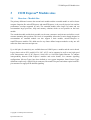
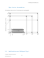
 COM Express™ Extension
Specification
Rev. 013
This page intentionally left blank
Table of Contents
Table of Contents
1
User Information......................................................................................................................... 5
1.1
1.2
1.3
1.4
2
Introduction................................................................................................................................. 6
2.1
2.2
2.3
2.4
3
About This Document...................................................................................................... 5
Copyright Notice ............................................................................................................. 5
Technical Support............................................................................................................ 5
Disclaimer........................................................................................................................ 5
COM Express™ Extension Specification ......................................................................... 6
COM Express™ Design Guide ......................................................................................... 6
COM Express™ Computer-On-Module ........................................................................... 6
Objective.......................................................................................................................... 8
COM Express™ Module sizes ..................................................................................................... 9
3.1
3.1.1
3.1.2
Overview - Module Size .................................................................................................. 9
Figure - Overview – three module sizes ........................................................................ 10
Small Form Factor nano, COM Express™ Type 1........................................................ 10
Figure 3 – Small Form Factor nano ............................................................................................. 11
4
Signal Description ..................................................................................................................... 12
4.1
4.1.1
4.1.2
5
Graphic Signal Description............................................................................................ 12
Table – Graphic Signal Description - Row C for Pin-out Type 2 ................................. 12
Table – Graphic Signal Description - Row D for Pin-out Type 2 ................................. 13
Hardware extensions................................................................................................................. 15
5.1
5.1.1
5.2
5.2.1
Wide Range Input Power............................................................................................... 15
Wide Range Input Power for nano SFF......................................................................... 15
GPIO General Purpose I/O Recommended Use ............................................................ 16
Alternative GPIO use for SDIO Interface...................................................................... 17
SDIO Pin description ....................................................................................................................... 17
5.3
6
Thermal Control............................................................................................................. 18
Software extensions................................................................................................................... 19
6.1
6.2
6.3
6.4
6.4.1
TPM support .................................................................................................................. 19
Smart Battery BIOS support .......................................................................................... 19
Legacy Super I/O support in BIOS................................................................................ 20
CMOS backup in BIOS ................................................................................................. 20
Console redirection in BIOS.......................................................................................... 20
Copyright © COM Express™ Extension
Specification Rev 012
iii
Table of Contents
6.4.2
7
Apendix A: PC Architecture Information .............................................................................. 21
7.1
7.1.1
7.1.2
7.2
7.3
7.3.1
7.3.2
7.3.3
7.4
8
User editor for default settings....................................................................................... 20
Buses.............................................................................................................................. 21
ISA, Standard PS/2 – Connectors .................................................................................. 21
PCI 21
General PC Architecture................................................................................................ 21
Ports ............................................................................................................................... 22
RS-232 Serial................................................................................................................. 22
Serial ATA..................................................................................................................... 22
USB ............................................................................................................................... 22
Programming ................................................................................................................. 23
APPENDIX B: DOCUMENT-REVISION HISTORY.......................................................... 24
Copyright © COM Express™ Extension
Specification Rev 012
iv
1 User Information
1
User Information
1.1
About This Document
This document provides information about products from Kontron Embedded Modules GmbH, and/or
its subsidiaries. No warranty of suitability, purpose, or fitness is implied. While every attempt has
been made to ensure that the information in this document is accurate, the information contained
within is supplied “as-is” and is subject to change without notice.
For the circuits, descriptions and tables indicated, Kontron assumes no responsibility as far as patents
or other rights of third parties are concerned.
1.2
Copyright Notice
Copyright © 2007 - 2008 COM Express™ Extension
Kontron Embedded Modules GmbH and Advantech Co., Ltd. are founding members of the COM
Industrial Group the purpose of which is the definition, marketing and promotion of the COM
Technologies.
Kontron Embedded Modules GmbH and Advantech Co., Ltd. Have significantly contributed to the
development and promotion of the COM Industrial Standard and administrates the COM Industrial
Group’s website (http://www.com-ig.org/).
All rights reserved. No part of this document may be reproduced, transmitted, transcribed, stored in a
retrieval system, or translated into any language or computer language, in any form or by any means
(electronic, mechanical, photocopying, recording, or otherwise), without the express written
permission of COM Industrial Group founding Members.
1.3
Technical Support
Technicians and engineers from COM Industrial Group Members are available for technical support.
We are committed to making our product easy to use and will help you use our products in your
systems.
http://www.comexpress-extension.org/members/members.php
Before contacting COM Industrial Group Members technical support, please consult our web site at
http://www.comexpress-extension.org for the latest product documentation, utilities, and drivers. If the
information does not help solve the problem, contact us by email.
http://www.comexpress-extension.org/contact/contact.php
1.4
Disclaimer
Although the information presented in this document was carefully reviewed and is believed to be
accurate, it is not guaranteed. The reader assumes all liability for the use of the information herein.
Copyright © COM Express™ Extension
5
Specification Rev 013
2 Introduction
2
Introduction
2.1
COM Express™ Extension Specification
The COM Express™ Extension Specification builds on the COM Express™ (COM.0) standard as
defined by the PCI Industrial Computer Manufacturers’ Group (PICMG®) which is an industry
standard adopted for Computer-On-Modules. The COM Express™ Extension Specification is focused
with its intellectual properties on the deep embedded market and is intended to be an add-on to the
PICMG’s COM Express™ COM.0 Specification. It is the intention of the authors of this specification
to propose the information contained here within to PICMG® as a means of updating the current
COM Express™ standard to ensure continued saleability and compatibility of all COM Express™
solutions.
2.2
COM Express™ Extension Design Guide
The COM Express™ Design Guide, a separate document from both the PICMG® COM Express™
Specification and this COM Express™ Extension Specification, is available to COM Express™ module
customers upon request. For download the COM Express™ Extension Design guide please visit our
web page:
http://www.comexpress-extension.com/specs/specs.php
The COM Express™ Design Guide explores the requirements of the COM Express™ Extension
Specification and provides recommendations on designing COM Express™ baseboards to support
various features of COM Express™ compliant modules.
The COM Express™ Design Guide, based upon the COM Express™ Extension Specification and
PICMG® COM Express™ Specification, discusses capabilities in the specification with schematic
examples where applicable and offers ideas to consider for maximum flexibility in designing
baseboards.
2.3
COM Express™ Computer-On-Module
A COM Express™ Computer-On-Module (COM) is a module with all components necessary for a
bootable host computer, packaged as a super component. COMs require a carrier board in order to
bring out I/O and to power up the CPU module.
COMs are used to build single board computer solutions and offer OEMs fast time-to-market with
reduced development cost.
Like integrated circuits, they provide OEMs with significant freedom when working to meet form-fitfunction requirements. For all of these reasons, COM methodology has gained significant popularity
with OEMs in the embedded industry. The COM Express™ standard is designed to be future proof
and to provide a smooth transition path from legacy parallel interfaces to LVDS (Low Voltage
Copyright © COM Express™ Extension
6
Specification Rev 013
2 Introduction
Differential Signalling) interfaces. These include the PCI bus and parallel ATA on the one hand and
PCI Express and Serial ATA on the other hand.
Key features include:
Rich complement of contemporary high bandwidth serial interfaces, including PCI
Express, Serial ATA, USB 2.0, and Gigabit Ethernet
32-bit PCI, LPC and Parallel ATA options preserved for easy interface to a range of
peripherals
Extended power-management capabilities
Robust thermal and mechanical concept
Cost-effective design
Legacy-free design (no Super I/O, PS2 keyboard or mouse)
COM Express™ module size with two currently defined footprint options (“Basic”
and “Extended”) to satisfy a range of performance requirements. The option for
future more compact footprints like microETXexpress and nanoETXexpress are
present.
High-performance mezzanine connector with several defined pin-out types to
satisfy a range of application requirements
The COM Express™ Extension specification has been created to support to a range of vertical
embedded markets. It has been formulated to be applicable to a broad range of system types, from
floor-installed and bench-top to mobile handheld.
Markets and applications include but are not limited to:
Healthcare - clinical diagnostic imaging systems, patient bedside monitors, etc.
Retail & advertising - electronic shopping carts, billboards, kiosks, POS/POI
systems, etc.
Gaming & entertainment - simulators, slot machines, etc.
Test & measurement - scientific and industrial test and measurement instruments
Industrial automation - industrial robots, vision systems, etc.
Security - digital CCTV, luggage scanners, intrusion detectors, etc.
Defence & government - unmanned vehicles, rugged laptops, wearable computers,
etc.
Systems developed according to the COM Express™ Extension Specification require the
implementation of an application-specific carrier board that accepts the module. The carrier board is
typically a 4- to 8-layer PCB. User-specific features such as external connector choices and locations
and peripheral circuits can be tailored to suit the application. The OEM can focus on applicationCopyright © COM Express™ Extension
7
Specification Rev 013
2 Introduction
specific features rather than caring for a CPU board design. The OEM also benefits from a wide
choice of modules providing a scalable range of price and performance upgrade options.
2.4
Objective
Consistent with the objective of the PICMG® COM Express™ Specification, the COM Express™
Extension specification defines COM Express™ compliant modules at a level of detail sufficient to
allow interoperability between independent vendor modules and carrier boards.
Copyright © COM Express™ Extension
8
Specification Rev 013
3 COM Express™ Module sizes
3
COM Express™ Module sizes
3.1
Overview - Module Size
The primary difference between the current basic module and the extended module as well as future
compact footprints like microETXexpress and nanoETXexpress is the over-all physical size and the
performance envelope supported by each. The extended module offers larger real estate and can
accommodate larger processor, chips and memory solutions which are not possible on the basic
module.
The extended module and the basic module use the same connectors and pin-outs and utilize several
common mounting hole positions. This level of compatibility allows that a carrier board designed to
accommodate an extended module can also support a basic module, microETXexpress or
nanoETXexpress modules. This holds true for any future defined compact modules as they too will
utilize the same connectors and pin-outs
Up to 440 pins of connectivity are available between COM Express™ modules and the carrier board.
Legacy buses such as PCI, parallel ATA, LPC, AC'97 can be supported as well as new high speed
serial interconnects such as PCI Express, Serial ATA or SAS and Gigabit Ethernet. To enhance
interoperability between COM Express™ modules and carrier boards, five common signalling
configurations (Pin-out Types) have been defined to ease system integration. Some Pin-out Types
definitions require only a single 220-pin connector, like nanoETXexpress and others require both 220pin connectors to supply all the defined signalling.
Copyright © COM Express™ Extension
9
Specification Rev 013
3 COM Express™ Module sizes
Figure - Overview – three module sizes
All coordinates in mm. top view ( X1 is on bottom side, seen through pcb)
3.1.1
Small Form Factor nano, COM Express™ Type 1
Copyright © COM Express™ Extension
10
Specification Rev 013
3 COM Express™ Module sizes
The PCB size for the nano module is defined as 55mm x 84mm.
The holes shown in this drawing are intended for mounting the module / heat-spreader combination to
the carrier board. An independent, implementation specific set of holes and spacers shall be used to
attach the heat-spreader to the module.
Figure - Small Form Factor nano
8
55
51
COM Express™ Type 1
4
4
80
Holes Compatible to COM Express™
ecification
All dimensions are shown in millimetres. Tolerances should be ± 0.25mm [±0.010"], unless noted
otherwise. The tolerances on the module connector locating peg holes (dimensions [16.50, 6.00])
should be ± 0.10mm [±0.004"].
The 220 pin connector shall be mounted on the backside of the PCB and is seen “through” the board in
this view. The X mounting holes shown should use 6mm diameter pads and should have 2.7mm plated
holes, for use with 2.5mm hardware. The pads should be tied to the PCB ground plane.
Copyright © COM Express™ Extension
11
Specification Rev 013
4 Signal Description
4
Signal Description
4.1
Graphic Signal Description
Based on the different available graphic interfaces offered by the different chipsets from silicon
vendors including Intel, ATI, VIA, etc., there is a need for optional assignment in addition to the ones
already defined by PICMG in the COM.0 specification. These will allow for ease when integrating
upcoming new graphic interfaces while still assuring compatibility of COM Express™ compliant
modules and carrier boards.
Graphic signals are defined on Row C and Row D.
The following table describes the signal uses up on the required graphic interface.
4.1.1
Table – Graphic Signal Description - Row C for Pin-out Type 2
Row C
Definition
Pin No.
C52
C53
C54
C55
C56
C57
C58
C59
C60
C61
C62
C63
C64
C65
C66
C67
C68
C69
C70
C71
C72
C73
C74
C75
C76
C77
PCIE x 16
Pin Name
PEG_RX0+
PEG_RX0TYPE0#
PEG_RX1+
PEG_RX1TYPE1#
PEG_RX2+
PEG_RX2GND (FIXED)
PEG_RX3+
PEG_RX3RSVD
RSVD
PEG_RX4+
PEG_RX4RSVD
PEG_RX5+
PEG_RX5GND (FIXED)
PEG_RX6+
PEG_RX6SDVO_DATA
PEG_RX7+
PEG_RX7GND
RSVD
SDVO
TMDS(DVI)/HDMI/DVO
Display Port
SDVO_TVCLK+
SDVO_TVCLKTYPE0#
SDVOB_INT+
SDVOB_INTTYPE1#
SDVO_FLDSTALL+
SDVO_FLDSTALLGND (FIXED)
HDMI_TVCLKIN
HDMI_TVCLKIN#
TYPE0#
TYPE0#
TYPE1#
TMDS_DDC_DAT
TMDS_DDC_CLK
GND (FIXED)
TMDS_HPD
TYPE1#
DPB_AUX
DPB_AUXB
GND (FIXED)
DPB_HPD
RSVD
RSVD
RSVD
RSVD
RSVD
RSVD
RSVD
SDVOC_INT+
SDVOC_INTGND (FIXED)
RSVD
RSVD
GND (FIXED)
TMDS_2_DDC_DAT
TMDS_2_DDC_CLK
GND (FIXED)
DPC_AUX
DPC_AUXB
TMDS_2_HPD
DPC_HPD
GND
RSVD
GND
RSVD
SDVO_DATA
Copyright © COM Express™ Extension
12
Specification Rev 013
4 Signal Description
C78
C79
C80
C81
C82
C83
C84
C85
C86
C87
C88
C89
C90
C91
C92
C93
C94
C95
C96
C97
C98
C99
C100
C101
C102
C103
C104
C105
C106
C107
C108
C109
C110
4.1.2
PEG_RX8+
PEG_RX8GND (FIXED)
PEG_RX9+
PEG_RX9RSVD
GND
PEG_RX10+
PEG_RX10GND
PEG_RX11+
PEG_RX11GND (FIXED)
PEG_RX12+
PEG_RX12GND
PEG_RX13+
PEG_RX13GND
RSVD
PEG_RX14+
PEG_RX14GND (FIXED)
PEG_RX15+
PEG_RX15GND
VCC_12V
VCC_12V
VCC_12V
VCC_12V
VCC_12V
VCC_12V
GND (FIXED)
DVO D11
DVO D10
GND (FIXED)
DVO D9
DVO D8
RSVD
GND
DVO D7
DVO D6
GND
DVO CLK+
DVO D5
GND (FIXED)
DVO D4
DVO D3
GND
DVO D2
DVO D1
GND
RSVD
DVO D0
DVO DE
GND (FIXED)
DVO HS
DVO VS
GND
VCC_12V
VCC_12V
VCC_12V
VCC_12V
VCC_12V
VCC_12V
GND (FIXED)
GND (FIXED)
RSVD
GND
DPD_AUX
DPD_AUXB
GND
DPD_HPD
GND (FIXED)
GND
GND
RSVD
GND (FIXED)
GND
VCC_12V
VCC_12V
VCC_12V
VCC_12V
VCC_12V
VCC_12V
GND (FIXED)
Table – Graphic Signal Description - Row D for Pin-out Type 2
Row D
Definition
Pin No.
D52
D53
D54
D55
D56
D57
D58
D59
D60
PCIE x 16
Pin Name
PEG_TX0+
PEG_TX0PEG_LANE_RV#
PEG_TX1+
PEG_TX1TYPE2#
PEG_TX2+
PEG_TX2GND (FIXED)
SDVO
TMDS(DVI)/HDMI/DVO
Display Port
SDVOB_RED+
SDVOB_REDPEG_LANE_RV#
SDVOB_GRE+
SDVOB_GRETYPE2#
SDVOB_BLU+
SDVOB_BLUGND (FIXED)
TMDS DATA 2+
TMDS DATA 2PEG_LANE_RV#
TMDS DATA 1+
TMDS DATA 1TYPE2#
TMDS DATA 0+
TMDS DATA 0GND (FIXED)
DPB_LANE0
DPB_LANE0#
PEG_LANE_RV#
DPB_LANE1
DPB_LANE1#
TYPE2#
DPB_LANE2
DPB_LANE2#
GND (FIXED)
Copyright © COM Express™ Extension
13
Specification Rev 013
4 Signal Description
D61
D62
D63
D64
D65
D66
D67
D68
D69
D70
D71
D72
D73
D74
D75
D76
D77
D78
D79
D80
D81
D82
D83
D84
D85
D86
D87
D88
D89
D90
D91
D92
D93
D94
D95
D96
D97
D98
D99
D100
D101
D102
D103
D104
D105
D106
D107
D108
D109
D110
PEG_TX3+
PEG_TX3RSVD
RSVD
PEG_TX4+
PEG_TX4GND
PEG_TX5+
PEG_TX5GND (FIXED)
PEG_TX6+
PEG_TX6SDVO_CLK
PEG_TX7+
PEG_TX7GND
IDE_CBLID#
PEG_TX8+
PEG_TX8GND (FIXED)
PEG_TX9+
PEG_TX9RSVD
GND
PEG_TX10+
PEG_TX10GND
PEG_TX11+
PEG_TX11GND (FIXED)
PEG_TX12+
PEG_TX12GND
PEG_TX13+
PEG_TX13GND
PEG_ENABLE#
PEG_TX14+
PEG_TX14GND (FIXED)
PEG_TX15+
PEG_TX15GND
VCC_12V
VCC_12V
VCC_12V
VCC_12V
VCC_12V
VCC_12V
GND (FIXED)
SDVOB_CLK+
SDVOB_CLKRSVD
RSVD
SDVOC_RED+
SDVOC_REDGND
SDVOC_GRE+
SDVOC_GREGND (FIXED)
SDVOC_BLU+
SDVOC_BLUSDVO_CLK
SDVOC_CLK+
SDVOC_CLK-
TMDS Clock +
TMDS Clock RSVD
RSVD
TMDS DATA 5+
TMDS DATA 5GND
TMDS DATA 4+
TMDS DATA 4GND (FIXED)
TMDS DATA 3+
TMDS DATA 3-
DPB_LANE3
DPB_LANE3#
RSVD
RSVD
DPC_LANE0
DPC_LANE0#
GND
DPC_LANE1
DPC_LANE1#
GND (FIXED)
DPC_LANE2
DPC_LANE2#
TMDS_2_CLK +
TMDS_2_CLK GND
IDE_CBLID#
DVO_SDA
DVO_SCL
GND (FIXED)
DVO_HPD
GND (FIXED)
DPC_LANE3
DPC_LANE3#
GND
IDE_CBLID#
DPD_LANE0
DPD_LANE0#
GND (FIXED)
DPD_LANE1
DPD_LANE1#
RSVD
GND
DPD_LANE2
DPD_LANE2#
GND
DPD_LANE3
DPD_LANE3#
GND (FIXED)
GND
GND
GND
PEG_ENABLE#
GND
PEG_ENABLE#
GND (FIXED)
GND (FIXED)
GND
VCC_12V
VCC_12V
VCC_12V
VCC_12V
VCC_12V
VCC_12V
GND (FIXED)
GND
VCC_12V
VCC_12V
VCC_12V
VCC_12V
VCC_12V
VCC_12V
GND (FIXED)
RSVD
GND
GND
DVO CLK-
Copyright © COM Express™ Extension
14
Specification Rev 013
5 Hardware extensions
5
Hardware extensions
Wide Range Input Power for basic, extended and micro form factor
Wide range input power: +8.5VDC to +18VDC
It allows direct operation from 108 nominal 3 cell lithium ion battery pack to 4-cell lithium-ion battery
packs (16,8 V fully charged)
Additionally, Smart Battery Support offers a great base for a mobile application. See Software section
for more details
5.1.1
Wide Range Input Power for nano SmallFormFactor (SFF)
The nano modules should use a single main power rail with a wide range power supply of 5V
to +14V+/-5% (4,75V to 14,7V)
Two additional rails are specified, a +5V standby power rail and a +3V battery input to power
the module real-time clock (RTC) circuit in the absence of other power sources. The +5V
standby rail could be left unconnected on the carrier board if the standby functions are not
required by the application. Likewise, the +3V battery input may be left open if the
application does not require the RTC to keep time in the absence of the main and standby
sources. There may be module specific concerns regarding storage of system setup parameters
that may be affected by the absence of the +5V standby and / or the +3V battery.
The rationale for this power-delivery scheme is:
•
Module pins are scarce. It is more pin-efficient to bring power in on a higher
voltage rail.
•
Single supply operation is attractive to many users.
•
Lithium ion battery packs for mobile systems are most prevalent with a +14.4V
output. This is well suited for the +12V main power rail.
•
Contemporary chipsets have no power requirements for +5V other than to provide a
reference voltage for +5V tolerant inputs. No COM Express™ module pins are
allocated to accept +5V except for the +5V standby pins. In the case of an ATX
supply, the switched (non standby) +5V line would not be used for the COM
Express™ module, but it might be used elsewhere on the carrier board.
Copyright © COM Express™ Extension
15
Specification Rev 013
5 Hardware extensions
5.2
GPIO General Purpose I/O Recommended Use
In general, GPIOs are defined for specific customers. Any generic GPIOs should be be set as well in
order to assure compatibility of various COM Express™ compliant modules and carrier boards.
GPI0
GPI1
GPI2
GPI3
GPO0
GPO1
GPO2
GPO3
Pin Description
General Purpose Input
General Purpose Input
General Purpose Input
General Purpose Input
General Purpose Output
General Purpose Output
General Purpose Output
General Purpose Output
Recomended Use
LID Button
Function
Power Management Event
Comment
Please see Board Specification
Fan Control
TTL output for external fan
Please see Board Specification
Copyright © COM Express™ Extension
16
Specification Rev 013
5 Hardware extensions
5.2.1
Pin
A54
A63
A67
A85
A93
Alternative GPIO use for SDIO Interface
GPIO
GPI0
GPI1
GPI2
GPI3
GPO0
SDIO
DATA0
DATA1
DATA2
DATA3
CLK
Pin
B54
B57
B63
GPIO
GPO1
GPO2
GPO3
SDIO
CMD
WP
CD#
SDIO Pin description
Signal
SD_DATA[3:0]
Type
I/O
CMOS3.3
SD_CMD
I/O
CMOS3.3
SD1_CLK
O
CMOS3.3
SD0_WP
I
CMOS3.3
I
CMOS3.3
SD1_CD#
Description
SDIO Controller 0/1/2 Data: These signals operate
in push-pull mode. The SD card includes internal pullup resistors for all data lines. By default, after powerup, only SDn_DATA0 is used for data transfer. Wider
data bus widths can be configured for data transfer.
SDIO Controller 0/1/2 Command: This signal is
used for card initialization and transfer of commands.
It has two operating modes: open-drain for
initialization mode, and push-pull for fast command
transfer.
SDIO Controller 0/1/2 Clock: With each cycle of this
signal a one-bit ransfer on the command and each
data line occurs.
This signal is generated by Intel SCH at a maximum
frequency of:
24 Mhz for SD and SDIO.
48 Mhz for MMC.
SDIO Controller 0/1/2 Write Protect: These signals
denote the state of the write-protect tab on SD cards.
SDIO Controller 0/1/2 Card Detect: Indicates when
a card is present in an external slot.
Copyright © COM Express™ Extension
17
Specification Rev 013
5 Hardware extensions
5.3
Thermal Control
A three-pin fan header is stuffed onboard the module to support thermal control through the use of a
fan. Through BIOS-settings, it is possible to control the fan depending on the Active Trip Point
temperature. The fan switches on/off depending on the adjusted Active Trip Point temperature. In
order for this feature to function properly, an ACPI compliant OS is necessary. (Except for
nanoETXexpress modules)
- Part number (Molex):
53261-0390
- Mates with:
51021-0300
- Crimp terminals:
50079-8100
Electrical characteristics:
- Vcc = 5 V
- Imax (continuous) = 0,68 A
- Imax (pulsed) = 2 A
- Sense (Tacho-pulse) = 4 Pulses per turn
Copyright © COM Express™ Extension
18
Specification Rev 013
6 Software extensions
6
Software extensions
6.1
TPM support
Trusted Computing is a technology developed and promoted by the Trusted Computing Group (TCG).
The term is taken from the field of trusted systems and has a specialized meaning. "Trusted
computing" means that the computer will consistently behave in specific ways and those behaviors
will be enforced by hardware and software.
Trusted computing encompasses five key technology concepts, of which all are required for a fully
trusted system.
Endorsement Key
Secure Input and Output
Memory curtaining / Protected execution
Sealed storage
Remote attestation
COM Express™ Extension COMs are designed to support basic TPM features.
(more information: TBD)
COM Express™ Extension COMs are compliant to TCG 1.2. That includes efficient processing of hash
and RSA algorithms with key length up to 2048bit and random generator.
This technology is necessary for all security -sensitive applications such as those for the gaming and ecommerce industries.
6.2
Smart Battery BIOS support
The BIOS supports smart battery to monitor the actual battery state on your system.
MARS is a Smart Battery reference System that is able to control up to two Smart batteries. The
reference system will be implemented on a customized carrier board. The core of the SBS MARS is a
dual Smart Battery System Manager. Additionally, the system contains a buck-boost converter at the
input side, a dual buck converter and a buck-boost converter at the output side. There is also a CPLD
used in MARS to get the functionality of an ATX power supply and for additional tasks.
Copyright © COM Express™ Extension
19
Specification Rev 013
6 Software extensions
MARS = Mobile Application platform for Rechargeable Systems
Please following the link listed below to the document where you can find more information regarding
a Smart Battery reference system:
http://emea.kontron.com/products/computeronmodules/etx/mars.html
6.3
Legacy Super I/O support in BIOS
Although COM Express™ is meant for legacy free systems there still often is the need for legacy
interfaces like serial port, parallel port, floppy, etc.
To make an adaption of these ports possible the BIOS of COM Express™ modules has integrated
support for LPC SUPER I/O chips. For detailed description, please see the COM Express™ Design
Guide.
More information:
http://www.comexpress-extension.com/datasheet/COM_Express_Design_Guide_Rev_14.pdf
6.4
CMOS backup in BIOS
CMOS backup is supported by the BIOS.
Customer settings are saved in spite of battery remove in the EEPROM.
6.4.1
Console redirection in BIOS
(More information: TBD)
6.4.2
User editor for default settings
(More information: TBD)
Copyright © COM Express™ Extension
20
Specification Rev 013
7 Apendix A: PC Architecture Information
7
Apendix A: PC Architecture Information
The following sources of information can help you better understand PC architecture.
7.1
Buses
7.1.1
ISA, Standard PS/2 – Connectors
AT Bus Design: Eight and Sixteen-Bit ISA, E-ISA and EISA Design, Edward
Solari, Annabooks, 1990, ISBN 0-929392-08-6
AT IBM Technical Reference Vol. 1 & 2, 1985
ISA & EISA Theory and Operation, Edward Solari, Annabooks, 1992, ISBN
0929392159
ISA Bus Specifications and Application Notes, Jan. 30, 1990, Intel
ISA System Architecture, Third Edition, Tom Shanley and Don Anderson,
Addison-Wesley Publishing Company, 1995, ISBN 0-201-40996-8
Personal Computer Bus Standard P996, Draft D2.00, Jan. 18, 1990, IEEE Inc
Technical Reference Guide, Extended Industry Standard Architecture Expansion
Bus, Compaq 1989
7.1.2
PCI
PCI SIG
The PCI-SIG provides a forum for its ~900 member companies, who develop PCI
products based on the specifications that are created by the PCI-SIG. You can
search for information about the SIG on the Web.
PCI & PCI-X Hardware and Software Architecture & Design, Fifth Edition,
Edward Solari and George Willse, Annabooks, 2001, ISBN 0-929392-63-9.
PCI System Architecture, Tom Shanley and Don Anderson, Addison-Wesley, 2000,
ISBN 0-201-30974-2.
7.2
General PC Architecture
Embedded PCs, Markt & Technik GmbH, ISBN 3-8272-5314-4 (German)
Hardware Bible, Winn L. Rosch, SAMS, 1997, 0-672-30954-8
Interfacing to the IBM Personal Computer, Second Edition, Lewis C. Eggebrecht,
SAMS, 1990, ISBN 0-672-22722-3
The Indispensable PC Hardware Book, Hans-Peter Messmer, Addison-Wesley,
1994, ISBN 0-201-62424-9
Copyright © COM Express™ Extension
21
Specification Rev 013
7 Apendix A: PC Architecture Information
The PC Handbook: For Engineers, Programmers, and Other Serious PC Users,
Sixth Edition, John P. Choisser and John O. Foster, Annabooks, 1997, ISBN 0929392-36-1
7.3
Ports
7.3.1
RS-232 Serial
EIA-232-E standard
The EIA-232-E standard specifies the interface between (for example) a modem
and a computer so that they can exchange data. The computer can then send data to
the modem, which then sends the data over a telephone line. The data that the
modem receives from the telephone line can then be sent to the computer. You can
search for information about the standard on the Web.
RS-232 Made Easy: Connecting Computers, Printers, Terminals, and Modems,
Martin D. Seyer, Prentice Hall, 1991, ISBN 0-13-749854-3
National Semiconductor
The Interface Data Book includes application notes. Type “232” as search criteria
to obtain a list of application notes. You can search for information about the data
book on National Semiconductor’s Web site.
7.3.2
Serial ATA
Serial AT Attachment (ATA) Working Group.
This X3T10 standard defines an integrated bus interface between disk drives and
host processors. It provides a common point of attachment for systems
manufacturers and the system. You can search for information about the working
group on the Web. We recommend you also search the Web for information on 4.2
I/O cable, if you use hard disks in a DMA3 or PIO4 mode.
7.3.3
USB
USB Specification.
USB Implementers Forum, Inc. is a non-profit corporation founded by the group
of companies that developed the Universal Serial Bus specification. The USB-IF
was formed to provide a support organization and forum for the advancement and
adoption of Universal Serial Bus technology. You can search for information
about the standard on the Web.
Copyright © COM Express™ Extension
22
Specification Rev 013
7 Apendix A: PC Architecture Information
7.4
Programming
C Programmer’s Guide to Serial Communications, Second Edition, Joe Campbell,
SAMS, 1987, ISBN 0-672-22584-0
Programmer’s Guide to the EGA, VGA, and Super VGA Cards, Third Edition,
Richard Ferraro, Addison-Wesley, 1990, ISBN 0-201-57025-4
The Programmer’s PC Sourcebook, Second Edition, Thom Hogan, Microsoft
Press, 1991, ISBN 1-55615-321-X
Undocumented PC, A Programmer’s Guide to I/O, CPUs, and Fixed Memory
Areas, Frank van Gilluwe, Second Edition, Addison-Wesley, 1997, ISBN 0-20147950-8
Copyright © COM Express™ Extension
23
Specification Rev 013
8 APPENDIX B: DOCUMENT-REVISION
HISTORY
8
APPENDIX B: DOCUMENT-REVISION
HISTORY
Revision
Date
Edited by
0.1
02.06.06
Z. Loncaric Created preliminary specification.
Changes
0.2
05.10.06
Z. Loncaric Index updates:
- no microETXexpress inputs anymore, now a separate specification
- new hardware, software and mechanical issues
0.3
02.04.07
Z. Loncaric Defined new chapter, 4.0 Signal Description, 4.1 Graphic signal description
0.4
02.04.07
Z. Loncaric Neutral document format. Update by comments of Aaron Su.
/ Aaron Su
0.5
15.05.07
Z. Loncaric Brand COM Express Extension, Updates for chapters: 4.1 Grafic signal description,
/ P. Müller 5.2 General GPIOs, 5.3 Thermal Control, 6.1 TPM Support, 6.3 Legacy SuperI/O
Support
0.6
16.05.07
C. Van De
Graaf
0.7
24.07.07
M. Ciolacu/ New neutral layout
N.
Feuerecker
1.1
31.05.08
VGG
1.1
02.06.08
G.Szczuka
Minor changes and grammar edits
1.2
11.06.08
VGG
Minor changes, enter reverence to micro and nano
1.3
12.12.2008
G.Szczuka
Correction of revision numbers 0.11 to 1.1 / 0.12 to 1.2
Minor message and grammar edits
Add 3.1.2 new small form factor nano, add 5.2.1alternative GPIO use for SDIO
interface, add 5.1.1 wide Range for SFF
Copyright © COM Express™ Extension
24
Specification Rev 013