1
Cisco Catalyst 4900M Switch Installation
Guide
September 2010
Americas Headquarters
Cisco Systems, Inc.
170 West Tasman Drive
San Jose, CA 95134-1706
USA
http://www.cisco.com
Tel: 408 526-4000
800 553-NETS (6387)
Fax: 408 527-0883
Text Part Number: 78-18350-02
THE SPECIFICATIONS AND INFORMA TION REGARDING TH E PRODUCT S IN TH IS MA NUAL A RE SUBJECT TO CH ANGE WITHOU T NOT ICE. AL L
STAT EM ENT S, INFORMA TIO N, AND RECOM MEN DATIONS IN THIS MANUA L ARE BEL IE VED T O BE ACCURATE BU T ARE PRESE NTE D WIT HOUT
WA RRAN TY OF AN Y KIN D, E XPRESS OR IMPLIED. USE RS MUST T AKE F ULL RE SPONSIBILITY FOR TH EIR APPL ICAT ION O F ANY PRODUCT S.
THE SOFTWARE L ICEN SE AND L IM ITE D WARRA NTY FO R T HE ACCOMPA NYIN G PRODUCT ARE SET FORT H IN T HE INFORMAT ION PACKET T HAT
SHIPPE D WIT H THE PRO DUCT AND A RE INCORPORAT ED HE REIN BY THIS RE FEREN CE . IF YOU A RE UNABLE TO L OCATE T HE SO FTWARE LICENSE
OR LIMIT ED WARRANT Y, CON TACT Y OUR CISCO REPRESE NTAT IVE FOR A COPY.
The follow ing informati on is for F CC compliance of Class A de vic es: T his equipme nt ha s been teste d and found to comply wi th the limits for a Class A digital de vic e, pursua nt
to part 15 of the FCC rule s. T he se limits are designed to provide rea sonable protection a ga inst harmful interference when the e quipme nt is operate d in a commercial
environment. T hi s e quipment gene rate s, uses, and ca n radi ate ra dio-fre quency ene rgy a nd, if not installe d and used in a ccordance with the instruction manual , may cause
ha rmful int erfere nc e to radio communications. Operation of this equipment in a reside ntia l are a is like ly to cause harmful interferenc e, in which case users w ill be requi red
to c orrec t the i nte rfe rence a t the ir own e xpense.
The following information is for FCC compliance of Class B devices: The equipment de sc ribed i n this manua l generates and may radiate radio-frequency energy. If it is not
insta lled in ac cordance with Cisco’s insta llation instructions, it may cause interfere nc e with radio and tele vision rece ption. T his e quipment has bee n te st ed a nd found to
comply wi th the limits for a Cla ss B digita l device in accordance wi th the spec ific ations in part 15 of the FCC rules. T he se spe c ifica tions are designed to provide rea sonable
prot ection a gai nst such interfe rence in a re sidentia l install ation. However, there is no guarantee that interference will not oc cur in a particular instal lation.
Modifying the equipme nt wi thout Cisc o’s w ritten authorization may re sult in the equipme nt no l onge r complying with FCC requi rements for Class A or Class B digital
de vic es. In t hat e vent, your right to use the equipment ma y be limited by FCC regula tions, and you ma y be re quire d to correct any i nterfe rence to ra dio or tele vision
communica tions at your own expense.
You ca n determine whether your equipment i s c ausing inte rfe rence by turni ng it off. If the int erfere nc e stops, it was probably caused by t he Cisco equipment or one of its
pe riphe ral devices. If the equipment c ause s interfe rence to ra dio or television rece ption, try to correct the interference by using one or more of the following measure s:
• T urn the tel evision or radio ante nna unti l the interfe rence stops.
• M ove the equipment t o one side or the othe r of the television or radio.
• M ove the equipment farthe r awa y from the tele vision or radio.
• Plug t he e quipment into a n outl et tha t is on a diffe rent circuit from the television or ra dio. (T ha t is, make certain the equipme nt a nd the television or ra dio are on circuits
control led by different circuit breakers or fuses.)
Modificat ions to this product not a uthorize d by Cisco Syste ms, Inc. could void the FCC approva l and negate your a uthority to opera te the product.
The Cisco i mplementation of T CP header compression is an adaptation of a progra m developed by the Unive rsity of Ca lifornia, Berke ley (UCB) as part of U CB’s public
domain version of the UNIX operating system. All rights reserved. Copyright © 1981, Rege nts of the University of California .
NOT WITHST ANDING ANY O THE R WARRANT Y HERE IN, AL L DOCUM ENT F ILE S AND SOFT WARE OF TH ESE SUPP LIE RS ARE PROVID ED “A S IS” WIT H
ALL FAULT S. CISCO AND T HE ABOV E-N AME D SUPPLIERS DISCL AIM ALL WARRANT IE S, EXPRESSE D OR IM PLIE D, IN CL UDING, WITH OUT
LIMIT ATION, TH OSE OF M ERCHANT ABILITY , FITNE SS FOR A PARTICU LAR PURPOSE A ND NONINFRIN GEME NT O R ARISING FROM A COURSE OF
DEA LIN G, USAGE , O R T RA DE PRACTICE.
IN NO E VENT SHALL CISCO OR ITS SUPPL IE RS BE L IABLE FOR A NY INDIRECT, SPECIAL, CONSE QUEN TIA L, OR INCID ENT AL DAM AGES, INCL UDING,
WITH OUT LIMIT ATION, LOST PROFIT S OR LOSS OR DAM AGE TO DAT A ARISING OUT OF THE USE OR INABILIT Y T O U SE T HIS MAN UAL, EVE N IF CISCO
OR IT S SU PPLIERS HAVE BE EN AD VISE D OF THE POSSIBILITY OF SUCH DA MAGE S.
Cisc o and the Cisco logo are trademarks or re gistered trademarks of Cisco a nd/or its affilia tes in the U.S. and other countries. To vie w a list of Cisco trademarks, go to this
URL: www.ci sc o.com/go/trade ma rks. Third-party tradema rks mentioned a re the property of their respective ow ners. T he use of the w ord pa rtner doe s not imply a partne rship
rel ationship betwe en Cisco and a ny other company. (1110R)
Cisc o Cataly st 4900M Swit ch Installation Guide
Copyright © 2008–2012 Cisco Syste ms, Inc. All rights rese rved.
C ON TE N TS
Preface
vii
Audience
vii
Organization
vii
Related Documentation viii
Hardware Documents viii
Software Documentation ix
Cisco IOS Documentation ix
Conventions x
Statement 1071—Warning Definition
xi
Obtaining Documentation and Submitting a Service Request
C H A PT E R
1
Product Overview
xvi
1-1
Catalyst 4900M Switch Chassis 1-1
Catalyst 4900M Switch Chassis Features 1-2
Catalyst 4900M Switch Chassis Physical and Environmental Specifications 1-3
Catalyst 4900M Switch Chassis Rear Panel Connections and Features 1-4
Front Panel LEDs 1-5
Chassis Cooling 1-6
Power Supplies 1-7
Environmental Monitoring of the Power Supplies 1-8
Power Management for the Catalyst 4900M Switch 1-8
Power Management Modes 1-8
Catalyst 4900M Half-Card Modules 1-8
WS-X4920-GB-RJ45 Half-Card Ethernet Module 1-9
WS-X4904-10GE Half-Card Ethernet Module 1-10
WS-X4908-10GE Half-Card Ethernet Module 1-11
WS-X4908-10G-RJ45 Half-Card Ethernet Module 1-13
Serial Number Location
C H A PT E R
2
Site Planning
1-14
2-1
Site Environmental Requirements
2-1
Site Power Requirements 2-2
Preinstallation Requirements
Warnings and Cautions 2-2
2-2
Cisco Catalyst 4900M Switch In stallatio n Guide
78-18350-02
iii
Contents
EMI Recommendations 2-3
Power Requirements and Heat Dissipation
Grounding Requirements
Site Planning Checklist
3
Installing the Switch
2-3
2-7
Safety Overview 2-7
Ensuring Safety 2-7
Working Safely with Electricity 2-8
Preventing Electrostatic Discharge Damage
C H AP TER
2-9
2-9
3-1
Checking the Contents
3-1
Rack-Mounting the Switch 3-2
Rack-Mounting Guidelines 3-2
Lifting the Chassis Safely 3-3
Required Installation Tools 3-4
Rack-Mounting the Catalyst 4900M Switch
Connecting Power to the Catalyst 4900M Switch
3-4
3-7
Connecting DC-Input Power to the Catalyst 4900M Switch
Optical Connections
3-9
3-13
Configurable Modules 3-13
Required Tools 3-14
Removing Switching Modules 3-14
Installing Switching Modules 3-16
Removing and Replacing the Power Supply 3-18
Required Tools 3-18
Removing a Power Supply 3-18
Installing a Power Supply 3-19
Removing and Replacing the Fan Assembly
Required Tools 3-20
Removing the Fan Assembly 3-20
Installing the Fan Assembly 3-21
Verifying the Installation 3-21
C H AP TER
4
Troubleshooting the Installation
Getting Started
3-20
4-1
4-1
Problem Solving to the System Component Level
Identifying Startup Problems
LED Readings 4-2
4-2
4-2
Cisco Catalyst 4900M Switch Installation Guide
iv
78-18350-02
Conten ts
Troubleshooting the Power Supply
Contacting Customer Service
4-4
4-4
A PP E N D I X
A
Specifications
A PP E N D I X
B
Compliance Information and Translated Safety Warnings
Console Port
A-1
A-1
10/100/1000BASE-T Management Port
A-2
Catalyst 4900M Switch Power Supply Specifications
A-2
B-1
Translated Safety Warnings B-1
Statement 258—Fan Tray Removal Warning B-2
Statement 1003—DC Power Disconnection B-3
Statement 1004—Installation Instructions B-4
Statement 1006—Chassis Warning for Rack-Mounting and Servicing B-6
Statement 1008—Class 1 Laser Product B-11
Statement 1011—Staring into Laser Beam B-13
Statement 1017—Restricted Area B-14
Statement 1019—Main Disconnecting Device B-16
Statement 1024—Ground Conductor B-17
Statement 1028—More Than One Power Supply B-20
Statement 1029—Blank Faceplates and Cover Panels B-22
Statement 1030—Equipment Installation B-25
Statement 1040—Product Disposal B-27
Statement 1045—Short-circuit Protection B-28
Statement 1051—Laser Radiation B-30
Statement 1072—Shock Hazard from Interconnections B-32
Statement 1074—Comply with Local and National Electrical Codes B-35
Statement 1075—Hazardous Voltage or Energy Present on DC Power Terminals
B-36
European Directives B-38
Statement 287—Declaration of Conformity to R&TTE Directive 1999/5/EC for the European
Community, Switzerland, Norway, Iceland and Liechtenstein B-38
Statement 2002—Declaration of Conformity with Regard to the Directives 2006/95/EC and
2004/108/EC B-39
Statement 6005—California Perchlorate Contamination Prevention Act (Title 22, California Code of
Regulations, Chapter 33) B-39
Statement 6003—Taiwan Battery
B-40
Statement 6004—EU Battery Disposal and Recycling
B-40
Statement 6005—California Perchlorate Contamination Prevention Act (Title 22, California Code of
Regulations, Chapter 33) B-40
Cisco Catalyst 4900M Switch In stallatio n Guide
78-18350-02
v
Contents
Statement 8000—Standards Compliance
B-40
Statement 2007—EMC Environmental Conditions for Products Installed in the European Union
B-42
EMC Class A Notices and Warnings B-42
Statement 257—Class A Notice for Taiwan and Other Traditional Chinese Markets B-42
Statement 340—Class A Warning for CISPR22 B-43
Statement 2017—Class A Notice for FCC B-44
Statement 2021—Class A Notice for Canada B-44
Statement 191—VCCI Class A Warning for Japan B-45
Statement 256—Class A Warning for Hungary B-45
Statement 294—Class A Warning for Korea B-46
GR-1089-CORE Issue 3 Documentation Statements B-46
Statement 7016—GR-1089-Core Intrabuilding Lightning—Immunity Requirements
B-46
GR-1089-CORE Issue 4 Documentation Statements B-46
Statement 7001—ESD Mitigation B-46
Statement 7005—Intra-building Lightning Surge and AC Power Fault B-46
Statement 7012—Equipment Interfacing with AC Power Ports B-47
Statement 7013—Equipment Bonding Networks B-47
Statement 7014—Installation Location B-47
Statement 7015—Equipment Bonding and Grounding B-47
Statement 7016—Battery Return Conductor B-47
Statement 7017—Minimum Steady State DC Input Voltage B-47
Statement 8003—Telecom Approvals Listing B-47
Statement 3023—FCC Part 68 Notice B-47
Statement 3015—CS-03 Certification for Canada B-49
Statement 8001—JATE Certification for Japan B-49
Japanese Electric Appliance and Radio Laws B-50
Statement 371—Power Cable and AC Adapter B-50
Statement 372—Wireless LAN Products B-50
Statement 384—Japanese Safety Reference Information
B-50
I NDE X
Cisco Catalyst 4900M Switch Installation Guide
vi
78-18350-02
Preface
This preface describes the aud ience, organization, and conventions of the Cisco Ca talyst 4900 M Switch
Ins tallation Gu ide and provides in formatio n o n how to obtain related documentatio n.
Audience
Only train ed and qualified service pers onnel (as d efin ed in IEC6095 0 and AZ/NZS 609 50) sh ould
install, replace, or serv ice th e equipment.
Organization
This guid e is organized as fo llows:
Ch apter
Title
Description
Chap ter 1
Product Overv iew
Describes the hardware featu res and functionality of the
Catalyst 4900 M switch .
Chap ter 2
Site Plannin g
Describes how to p repare y our site for the installation of th e
switch.
Chap ter 3
Installing the Switch Details how to ins tall the Cataly st 4 900M switch.
Chap ter 4
Troub lesh ooting the
Installation
Provides tro ubleshooting g uidelin es for the initial hard ware
installation and sugg ests steps to help is olate and resolve
pro blems .
App end ix A
Sp ecificatio ns
Lists the Cataly st 4 900M switch system specifications.
App end ix B
Translated Safety
Warnings
Repeats in mu ltip le languages th e warn ings in this guide.
Cisco Catalyst 4900M Switch In stallatio n Guide
78-18350-02
vii
Pre face
Related Documentation
Related Documentation
Althoug h th eir Release Notes are un iq ue, the 4 p latforms (Catalyst 4500 , Catalyst 490 0, Catalys t ME
4 900, an d Catalyst 490 0M) us e the same So ftwa re Configuratio n Guide, Command Reference Guide, and
S ystem Messag e Guid e. Refer to th e following home pages for addition al information:
•
Cataly st 4 500 Series Switch Documentation Home
•
Cataly st 4 900 Series Switch Documentation Home
h ttp://www.cisco.com/go/cat4500/d ocs
h ttp://www.cisco.com/go/cat4900/d ocs
•
Cisco ME 4900 Series Ethern et Switches Documen tation Home
h ttp://www.cisco.com/en/US/products/ps70 09/tsd_p rod ucts_ suppo rt_series_h ome.html
Hardware Documents
Installatio n guides and n otes inclu ding sp ecificatio ns and relevant safety info rmation are available at th e
followin g URLs:
•
Cata lyst 450 0 S eries Switches In stallation Guide
•
Cata lyst 450 0 E-series Switches Insta llation Guid e
h ttp://www.cisco.com/en/US/docs/switches/lan/catalyst450 0/hardware/in stallation/gu ide/7 8-14 409
-08/45 00inst.html
h ttp://www.cisco.com/en/US/docs/switches/lan/catalyst450 0/hardware/catalys t4 500e/installatio n/g
u ide/Eseries.html
•
For in formatio n abo ut in div idual switch ing modules an d s uperviso rs, refer to the Ca talyst 45 00
S eries Mod ule Installation Guide at:
h ttp://www.cisco.com/en/US/docs/switches/lan/catalyst450 0/hardware/mo dule/guide/mod_ins t.ht
ml
•
Regulato ry Compliance and S afety Info rmation fo r the Catalyst 4 500 Series Switches
h ttp://www.cisco.com/en/US/docs/switches/lan/catalyst450 0/hardware/reg ulato ry/compliance/7 8_
1 3233.html
•
Installatio n n otes for specific su pervisor en gines o r for accesso ry hard ware are available at:
h ttp://www.cisco.com/en/US/products/hw/switches /ps4324 /prod _installatio n_guides_list.html
•
Cataly st 4 900 and 4900M hardware installation information is available at:
h ttp://www.cisco.com/en/US/products/ps60 21/prod_ins tallation_g uides_list.html
•
Cisco ME 4900 Series Ethern et Switches ins tallation info rmation is available at:
h ttp://www.cisco.com/en/US/products/ps70 09/prod_ins tallation_g uides_list.html
Cisco Catalyst 4900M Switch Installation Guide
viii
78-18350-02
Preface
Related Do cumentation
Software Documentation
Software releas e notes, configuration g uides, comman d references , and system message g uides are
availab le at the following URLs:
•
Catalyst 4500 release no tes are available at:
•
Catalyst 4900 release no tes are available at:
http://www.cisco.com/en/US/p rodu cts/h w/switches/ps43 24/prod_release_ notes_list.html
http://www.cisco.com/en/US/p rodu cts/p s6021/p rod_ release_notes_list.html
•
Cisco ME4900 490 0 Series Ethernet Switch release notes are availab le at:
http://www.cisco.com/en/US/d ocs/s witches/lan/catalyst4 500/release/no te/OL_11 511.html
Software documents fo r the Cataly st 4 500 Classic, Catalyst 4500 E-Series , Catalyst 490 0, and
Cisco ME 4 900 Series Eth ernet Switches are available at the following URLs:
•
Catalyst 4 500 Series So ftwa re Configuration Guide
•
Catalyst 4 500 Series So ftwa re Command Reference
http://www.cisco.com/en/US/p rodu cts/h w/switches/ps43 24/products_installation_and_configurati
on_g uides_list.html
http://www.cisco.com/en/US/p rodu cts/h w/switches/ps43 24/prod_command_reference_lis t.html
•
Catalyst 4 500 Series So ftwa re Sys tem Mes sage Guide
http://www.cisco.com/en/US/p rodu cts/h w/switches/ps43 24/products_sys tem_message_guides_list
.h tml
Cisco IOS Documentation
Platform-independent Cisco IOS documentatio n may als o ap ply to th e Catalyst 450 0 an d 490 0 switches.
These d ocu ments are available at the following URLs:
•
Cisco IOS con figuratio n guides, Release 1 2.x
•
Cisco IOS command references, Release 12.x
•
Cisco IOS system messages, version 1 2.x
•
Fo r info rmation about MIBs, refer to:
http://www.cisco.com/en/US/p rodu cts/p s6350/p rodu cts_ installation_ and _co nfigu ration_gu ides _lis
t.h tml
http://www.cisco.com/en/US/p rodu cts/p s6350/p rod_ co mmand _reference_list.html
You can also use the Command Loo kup To ol at:
http://tools.cisco.com/Supp ort/CLILoo kup/cltSearchAction .do
http://www.cisco.com/en/US/p rodu cts/p s6350/p rodu cts_ system_mess age_gu ides _list.h tml
You can also use the Erro r Messag e Decoder tool at:
http://www.cisco.com/p cgi-bin/Supp ort/Errord ecoder/in dex.cgi
http://www.cisco.com/p ublic/sw-center/netmgmt/cmtk/mibs.shtml
Cisco Catalyst 4900M Switch In stallatio n Guide
78-18350-02
ix
Pre face
Related Documentation
Conventions
This documen t u ses the following co nvention s:
Conven tion
Description
boldface font
Commands an d keyword s are in boldface.
italic font
Arguments for which you sup ply values are in italics.
[ ]
Elemen ts in sq uare b rackets are o ptional.
{ x | y| z }
Altern ative k eywords are gro uped in b races and
separated by vertical bars.
[ x |y | z ]
Op tional alternative key words are group ed in brackets
and sep arated by vertical bars.
string
A non -qu oted set of characters. Do n ot u se quo tation
marks aroun d the string, because the s tring will inclu de
the q uotation marks.
screen font
Terminal sessions and information that the system
displays are in screen font.
boldface screen
In formatio n that you mu st enter is shown in boldface
screen font.
font
italic screen
font
Arguments for which you sup ply values are in italic
font.
screen
Ctrl-
Ctrl- represents the key lab eled Contro l—fo r example,
the k ey combination Ctrl-D means to ho ld d own the
Control key wh ile you press th e D key.
< >
Characters th at do not print, su ch as pass words, are
shown within angle brackets.
Notes u se the following conventions :
Note
Means reader take note. Notes contain helpfu l su ggestions or references to material not covered in the
p ublication .
Cautions use the followin g conventions:
Caution
Mean s reader be careful. In this situation, you might do so mething th at could result in eq uipment
d amage o r loss of data.
Cisco Catalyst 4900M Switch Installation Guide
x
78-18350-02
Preface
Related Do cumentation
Warnings use the following conventions:
Statement 1071—Warning Definition
Warning
IMPORTANT SAFETY INSTRUCTIONS
This warning symbol means danger. You are in a situation that could cause bodily injury. Before you
work on any equipment, be aware of the hazards involved with el ectrical circuitry and be famili ar
with standard practices for preventing accidents. Use the statement number provi ded at the end of
each warning to locate its translation in t he transl ated safety warnings that accompanied this
device.
SAVE THESE INSTRUCTIONS
Waar schuwing
BELANGRIJKE VEILIGHEIDSINSTRUCTIES
Dit waarschuwingssymbool bet ekent gevaar. U verkeert in een situatie die lichamelijk letsel kan
veroorz aken. Voordat u aan enige apparatuur gaat werken, dient u zich bewust te zijn van de bij
elektrische schakelingen betrokken risico's en dient u op de hoogte te zijn van de standaard
praktijken om ongelukken te voorkomen. Gebruik het nummer van de verklaring onderaan de
waarschuwing als u een vertaling van de waarschuwing die bij het apparaat wordt geleverd, wilt
raadplegen.
BEWAAR DEZE INSTRUCTIES
Varoitus
TÄRKEITÄ TURVALLISUUSOHJEITA
Tämä varoitusmerkki merkit see vaaraa. Til anne voi aiheuttaa ruumiillisi a vammoja. Ennen kuin
käsittelet laitteistoa, huomioi sähköpiirien käsittelemiseen liittyvät riskit ja tutustu
onnettomuuksien yleisiin ehkäisytapoihin. Turvallisuusvaroitusten käännökset löytyvät lai tteen
mukana toimitettujen käännettyjen turvallisuusvaroitusten joukosta varoitusten lopussa näkyvien
lausuntonumeroiden avulla.
SÄILYTÄ NÄMÄ OHJEET
Attention
IMPORTANTES INFORMATIONS DE SÉCURITÉ
Ce symbole d'averti ssement indique un danger. Vous vous trouvez dans une si tuation pouvant
entraîner des blessures ou des dommages corporels. Avant de travail ler sur un équipement , soyez
consci ent des dangers l iés aux circuits électriques et familiarisez -vous avec les procédures
couramment utilisées pour éviter les accidents. Pour prendre connai ssance des traductions des
avertissements figurant dans les consignes de sécurité traduites qui accompagnent cet appareil,
référez-vous au numéro de l'i nstruction situé à l a fin de chaque avertissement.
CONSERVEZ CES INFORMATIONS
Cisco Catalyst 4900M Switch In stallatio n Guide
78-18350-02
xi
Pre face
Related Documentation
Warnung
WICHTIGE SICHERHEITSHI NWEISE
Dieses Warnsymbol bedeutet Gefahr. Sie befinden sich in einer Situation, di e zu Verlet zungen führen
kann. Machen Sie sich vor der Arbeit mit Geräten mit den Gefahren elektri scher Schaltungen und
den üblichen Verfahren zur Vorbeugung vor Unfällen vertraut. Suchen Sie mit der am Ende jeder
Warnung angegebenen Anweisungsnummer nach der jeweiligen Übersetzung i n den übersetzten
Sicherheitshinweisen, die zusammen mit diesem Gerät ausgeliefert wurden.
BEWAHREN SIE DIESE HI NWEISE GUT AUF.
Avvertenza
IMPORTANTI ISTRUZIONI SULLA SICUREZZA
Questo simbol o di avvertenza indica un pericolo. La situazione potrebbe causare infortuni alle
persone. Prima di intervenire su qualsiasi apparecchiatura, occorre essere al corrente dei pericoli
relat ivi ai circuiti elettrici e conoscere le procedure st andard per la prevenzione di incidenti.
Utilizzare il numero di istruzione present e alla fi ne di ciascuna avvertenz a per i ndividuare le
traduzioni delle avvertenze riportate i n questo documento.
CONSERVARE QUESTE ISTRUZIONI
Advar sel
VIKTIGE SIKKERHETSINSTRUKSJONER
Dette advarselssymbolet bet yr fare. Du er i en situasjon som kan føre til skade på person. Før du
begynner å arbeide med noe av ut styret, må du være oppmerksom på farene forbundet med
elektriske kretser, og kjenne til standardprosedyrer for å forhindre ulykker. Bruk nummeret i slutten
av hver advarsel for å finne oversettelsen i de oversatte sikkerhetsadvarslene som fulgte med denne
enheten.
TA VARE PÅ DISSE INSTRUKSJONENE
Av iso
INSTRUÇÕES IMPORTANTES DE SEGURANÇA
Este símbolo de aviso significa perigo. Você está em uma sit uação que poderá ser causadora de
lesões corporais. Antes de iniciar a utilização de qualquer equipamento, tenha conhecimento dos
perigos envolvidos no manuseio de circuitos elétricos e familiarize-se com as práticas habit uais de
prevenção de acidentes. Utilize o número da instrução fornecido ao f inal de cada aviso para
localizar sua tradução nos avisos de segurança traduz idos que acompanham este dispositivo.
GUARDE ESTAS INSTRUÇÕES
¡Adv ertencia!
INSTRUCCIONES IMPORTANTES DE SEGURIDAD
Este símbolo de aviso indica peli gro. Existe riesgo para su integridad físi ca. Antes de manipular
cualquier equipo, considere los riesgos de la corriente eléctrica y fami liarí cese con los
procedimientos estándar de prevención de accidentes. Al f inal de cada advertencia encontrará el
número que le ayudará a encontrar el texto traducido en el apartado de traducciones que acompaña
a este dispositivo.
GUARDE ESTAS INSTRUCCIONES
Cisco Catalyst 4900M Switch Installation Guide
xii
78-18350-02
Preface
Related Do cumentation
Varning!
VIKTIGA SÄKERHETSANVISNINGAR
Denna varningssignal signalerar fara. Du befinner dig i en situation som kan leda till personskada.
Innan du utför arbet e på någon utrustning måste du vara medveten om farorna med elkretsar och
känna till vanl iga förfaranden för att förebygga olyckor. Använd det nummer som finns i slutet av
varje varning för att hitta dess översättning i de översatta säkerhetsvarningar som medf öljer denna
anordning.
SPARA DESSA ANVISNINGAR
Cisco Catalyst 4900M Switch In stallatio n Guide
78-18350-02
xiii
Pre face
Related Documentation
Av iso
INSTRUÇÕES IMPORTANTES DE SEGURANÇA
Este símbolo de aviso significa perigo. Você se encontra em uma situação em que há ri sco de lesões
corporais. Antes de trabalhar com qualquer equipamento, esteja ciente dos riscos que envolvem os
circuitos elétricos e familiarize-se com as práticas padrão de prevenção de acidentes. Use o
número da declaração fornecido ao final de cada aviso para localizar sua tradução nos avisos de
segurança traduz idos que acompanham o dispositivo.
GUARDE ESTAS INSTRUÇÕES
Advar sel
VIGTIGE SIKKERHEDSANVISNINGER
Dette advarselssymbol betyder fare. Du befi nder dig i en situat ion med risi ko for
legemesbeskadigelse. Før du begynder arbejde på udstyr, skal du være opmærksom på de
involverede risici, der er ved elektriske kredsløb, og du skal sætte di g ind i standardprocedurer til
undgåelse af ul ykker. Brug erklæringsnummeret efter hver advarsel for at finde oversættelsen i de
oversatte advarsler, der fulgte med denne enhed.
GEM DISSE ANVISNINGER
Cisco Catalyst 4900M Switch Installation Guide
xiv
78-18350-02
Preface
Related Do cumentation
Cisco Catalyst 4900M Switch In stallatio n Guide
78-18350-02
xv
Pre face
Related Documentation
Obtaining Documentation and Submitting a Service Request
For in formatio n o n obtaining documentatio n, su bmitting a service request, and gathering additional
in formatio n, see th e mo nthly What’s New in Cisco Product Documentation, which also lists all new and
revis ed Cisco technical documentation, at:
h ttp://www.cisco.com/en/US/docs/general/whatsnew/whatsn ew.h tml
Subscribe to the Wh at’s New in Cisco Pro duct Docu mentation as a Really Simple Syndication (RSS) feed
and set content to be delivered directly to your desktop using a reader application. The RSS feeds are a free
service and Cisco currently supports RSS Version 2.0.
Cisco Catalyst 4900M Switch Installation Guide
xvi
78-18350-02
CH AP T E R
1
Product Overview
Revis ed: January 4, 2012
This chap ter describes the Catalyst 4900 M switch and the supported half-card Eth ernet mod ules . The
ch apter contains these sectio ns:
•
Catalyst 4900 M Switch Chassis, p age 1-1
•
Catalyst 4900 M Half-Card Mo dules, page 1-8
•
Serial Nu mber Locatio n, page 1-14
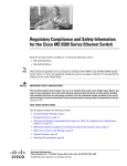
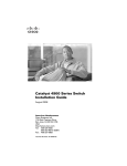
Catalyst 4900M Switch Chassis
The Catalyst 4900M switch is a 2 RU horizo ntal high -performan ce ded icated Ethernet s witch. Th e
ch assis has 8 fixed 1-GB or 10 -GB ports and two half-card Eth ernet module slo ts that can accommodate
a several different styles o f half-card Ethernet modules. The switch has one removable variab le-speed
fan tray an d s upports redund ant power supplies. Figure 1-1 shows th e front of th e chass is.
Cisco Catalyst 4900M Switch Installation Guid e
78-18350-02
1-1
Chapter 1
Product Overview
Catalyst 4900M Switch Chassis
Catalyst 4900M Switch Chassis
232121
Figure 1-1
Catalyst 4900M Switch Chassis Features
Tab le 1-1 lists th e features of the Catalyst 4900 M s witch chassis.
Table 1-1
Catalyst 4900M Switch Features
Feature
Description
Chas sis
8-p ort fixed configu ration plus 2 half-card module s lo ts
Uplin k p orts
8 10-Gigabit ports that suppo rt X2 tran sceivers. By usin g th e Cisco OneX
co nverter, the 8-ports also su pport SFP+ trans ceivers.
Slots
2 half-card module slots are available allowing you to con figure the chassis
to your s pecific needs.
Memo ry
512-MB SDRAM, 1 28-MB Flash (on board and fixed), 256 bytes serial
EEROM
Console port
A console s erial port (RJ-45) provides fo r switch man agement using
stan dard console equ ipmen t. (See Figure 1-2.)
Note
Ethern et manag ement port
A con sole cable is not provided in the accesso ry k it. It can be ordered
as an op tio n.
The managemen t p ort on the rear pan el offers the same TCP/IP b ased
man agement services available via inband access (telnet SNMP etc.). IP
ad dress co nfigu ration via BOOTP is sup ported on the Man agement port; it
also su pports image downlo ad to the s witch.
Cisco Catalyst 4900M Switch Installation Guide
1-2
78-18350-02
Chapter 1
Product Overview
Catalyst 4900M Switch Chassis
Table 1-1
Catalyst 4900M Switch Features (continued)
Feature
Description
Reset switch
Th e Reset button is used to restart the switch. Use a p ap er clip o r oth er small,
po inted ob ject to p ress the Reset button .
Fan tray
Variable-speed. Field replaceable.
Power sup plies
10 00 W AC-in put and 1 000 W DC-inpu t power supplies are su pported.
Note
A console cable is not provided as part of the accessory kit. It is available as an op tio n.
Catalyst 4900M Switch Chassis Physical and Environmental Specifications
Table 1 -2 lists the Cataly st 4 900M switch chas sis environmental and physical sp ecificatio ns.
Table 1-2
Catalyst 4900M Switch Specifications
Item
Specification
Environmental
Temp eratu re, op erating
Certified for operation: 32 ° to 1 04°F (0 ° to 40°C)
Design ed and tested for operation : 3 2° to 131°F (0° to 55°C)
Note
Temp eratu re, no noperating
and storag e
Humidity (RH), ambient
(noncondensin g) operating
Altitu de, operating
Heat Dissipation
The Catalyst 4900M s witch is equ ipped with internal air temperature
sens ors that are triggered at 49 °C (120.2°F) generating a minor alarm
and at 64°C (147.2°F) generating a major alarm. The system will shut
down at 67°C (152.6°F).
–40 ° to 167°F (–40° to 75°C)
10 % to 90%
Certified for operation: –1 97 to 6562 ft (–60 to 2000 m)
13 64 BTU/ho ur (worst case)
Physical Characteristics
Dimensio ns (H x W x D)
Weight
Airflow
1.
•
3.5 x 17.2 x 17.9 in. (8.9 x 43.7 x 45.5 cm).
•
Chassis requires 2 RU1 .
•
Th e Catalyst 490 0M switch chassis is designed to in stall in standard
19 -inch eq uipment racks that meet ANSI/EIA 310-D, IEC 602 97, and
ETS 30 0-1 19 stan dards.
34 .0 lb (15.4 kg) (max)
151.7 CFM (max)
RU = rack un its
Cisco Catalyst 4900M Switch Installation Guid e
78-18350-02
1-3
Chapter 1
Product Overview
Catalyst 4900M Switch Chassis
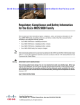
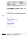
Catalyst 4900M Switch Chassis Rear Panel Connections and Features
Figure 1 -2 shows th e chass is rear p anel with the major features id entified .
Figure 1-2
View of the Rear Panel
2
1
2
3
232122
1
4
5
7
8
6
1
2
Input OK LED (power
su pply)
Output OK LED (power
su pply)
5
6
Console port
Man ag ement port
3
Fan Status LED
7
USB con nector
4
Reset butto n
8
Compact Flash slo t
The chassis rear pan el features include:
•
•
•
•
•
Reset button—The Reset button is used to res tart the switch. Use a paper clip or other small, pointed
o bject to press the Reset butto n.
Con sole po rt—A cons ole serial port (RJ-45 ) provides for switch management usin g s tand ard
conso le equipment. (See Figure 1-2.) A con nector p inout table is provided in Appendix A,
“Specifications,” for th e console and management po rts.
Managemen t po rt—The Management port on the rear panel offers the same TCP/IP based
management serv ices available via inb and access (telnet SNMP etc.). IP address config uration via
BOOTP is sup ported on the Man agement port; it als o su pports image downlo ad to the switch.
USB connector—A USB conn ector is provided for futu re expansion .
Comp act Flash slot—The Compact Flash slot accepts bo th 6 4-MB and 128-MB Type 1 comp act
Flash cards. You can use it for file transfer tasks such as lo adin g a new s oftware image. The Flash
card is option al and can be o btained from third-p arty suppliers.
For more information, refer to Using the Compa ct Flash o n th e Catalyst 4500 Series S uperviso r
Engines at the followin g URL:
h ttp://www.cisco.com/en/US/docs/switches/lan/catalyst450 0/hardware/configuration /notes/OL_ 27
8 8.h tml
Cisco Catalyst 4900M Switch Installation Guide
1-4
78-18350-02
Chapter 1
Product Overview
Catalyst 4900M Switch Chassis
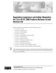
Front Panel LEDs
A set of LEDS on the ch assis front pan el (see Figure 1-3) pro vide visual status for the s witch. Table 1 -3
lists the fron t panel LEDS and their meaning s.
Figure 1-3
4
Chassis Front Panel LEDs
1
3
5
1
PS1 LED
2
PS2 LED
3
Fan LED
Table 1-3
4
System LED
5
10 Gig port LEDs
Front Panel LED Descriptions
LED
Description
System
Th e sys tem LED indicates the operating state of the Cataly st 4 900M
switch. At startup , the Catalyst 4900M performs a series o f
diagno stic tests:
(front)
•
•
CON
Console port
•
Note
•
•
Note
(front)
Red—A test other than an individu al port test fails
Off— Sy stem is in rommon mod e or a power sup ply has failed
Switch is disab led
Green —10/10 0 BASE-T console port is in link-up state
(rear)
Port
Green —All tes ts pass
•
•
(rear)
MGT
232123
2
•
•
Off— 10/100 BASE-T con sole port is in link-down state or no t
connected
There are no blin king, red, or yellow states for this port
Green —10/10 0/1000BASE-T Management port is in link-up
state.
Off— 10/100 /1000BASE-T Manag ement port is in link-down
state or not con nected.
There are no blin king, red, or yellow states for this port.
Green —Port is operational.
Yellow—Po rt is disabled by user.
•
Flashing yellow—Power-on self-test indicates faulty po rt.
•
Off— No signal detected or link co nfiguration failure.
Cisco Catalyst 4900M Switch Installation Guid e
78-18350-02
1-5
Chapter 1
Product Overview
Catalyst 4900M Switch Chassis
Table 1-3
Front Panel LED Descriptions (continued)
LED
Description
Fan
FAN LED indicates the fan tray status .
(front and rear)
PS1 and PS2
(front)
LINK
1.
•
Green—Fan tray operational.
•
Red— Fault detected . On e or mo re fans n ot functional.
•
Off—No p ower to the fan tray.
PS1 and the PS2 LEDs indicates the intern al power s upply status.
•
Off—No p ower to the power supply.
•
Green—Operational. 1
•
Red— Fault detected or th e on/off switch is set to off while th e
power sup ply is p lugged in.
A link status LED is located below the 1 0-GB u plink ports.
If either LED is green and the other is OFF the power supp ly is probably not plu gged in. If it is red, the
supply is either plugg ed in and not switched on or it is fau lty . It may be neces sary to in terrog ate the system
fo r further status using the CLI.
Chassis Cooling
The ho t-swapp able ch assis fan tray (WS-X499 2) provides coo ling air for th e internal ch assis
compo nen ts. Th e fans draw air in from the right side of the chassis and exh aust the heated air th rou gh
p erforations on the right side of the chassis.
Caution
When the fan tray is removed, internal circuitry is exp osed that should not be touched by to ols or fingers .
The system sho uld n ot operate without a fan tray for lo nger th an is necessary to replace a fau lty fan tray
with a new fan tray.
Figure 1 -4 shows th e direction of airflow through the switch.
Cisco Catalyst 4900M Switch Installation Guide
1-6
78-18350-02
Chapter 1
Product Overview
Catalyst 4900M Switch Chassis
Catalyst 4900M Chassis Airflow
232124
Figure 1-4
There are five fans in the fan tray. If an in dividual fan fails , the o ther fans co ntinue to run. Senso rs
monitor the internal air temperatures. The number of fan s in operation and their sp eed varies according
to the intern al temperature for the quietest o peration possible. If the air temperature exceeds a desired
thresho ld, the environmental mon itor disp lays warning mes sages.
Note
Ind iv idual fan s in the fan tray canno t be replaced; the entire fan tray must be replaced.
Power Supplies
Note
Fo r co mplete power specification s for th e Catalyst 490 0M s witch, see Appendix A, “Specification s.”
The Catalyst 4900M switch has two redu ndant in ternal 1 000 W AC-input or 10 00 W DC-input power
supplies.
The internal p ower supp lies have individu al power cords an d status LEDs (PS1 an d PS2 on the front
panel). Th ere are also LEDs o n the power supp lies that show status for th e input (Inpu t OK) and o utput
(Output OK) cu rren ts. A power cord is used to con nect the power su pplies to the site AC so urce. There
is a power switch on th e AC-inp ut power supp lies; AC power is present when a power cord is plugged
into a power supply and the switch is set to th e On po sition. DC-inp ut p ower supp lies attach to source
DC using customer-supplied cables.
The switch starts with only one p ower supply plug ged in, bu t redu ndant failover and load sharin g is not
availab le in this co nfiguration. Cisco recommen ds that you always co nnect both power supplies to
sep arate AC o r DC circuits for o ptimal power reliability.
Cisco Catalyst 4900M Switch Installation Guid e
78-18350-02
1-7
Chapter 1
Product Overview
Catalyst 4900M Half-Card Modules
For safety reas ons, the AC power supp ly must be switched off and unplug ged befo re it is removed from
a chassis or inserted in to a chassis. DC supp lies should have power shut off from the sou rce before they
are removed.
If only o ne power supply is used, y ou must use the supplied blank faceplate to cover the empty power
b ay. Th e blank power su pply co ver maintains EMI s hield in g and p roper air flow thro ugh the chassis.
Environmental Monitoring of the Power Supplies
Using th e environmental mo nitorin g and rep orting fu nctio ns, you can maintain normal system operation
by res olving adverse environmental condition s p rior to lo ss o f operation.
Each power supply mo nitors its own temp eratu re an d output vo ltages. The Catalyst 4900 M switch sen ses
th e operating condition o f the power supply and repo rts status throu gh software.
Power Management for the Catalyst 4900M Switch
You can select either AC-inpu t or DC-input p ower su pplies for your switch. Th e Catalyst 4900M switch
su pports th e following power supplies:
•
1 000 W AC-in put
•
1 000 W DC-inpu t
A redundant power su pply can be iden tified and diagno sed by a runn ing system regardles s o f its in put
status. The AC-inpu t and DC-input supp lies are interchan geable.
Power Management Modes
The Catalys t 49 00M switch suppo rts the redundant power management mod e. In this mode, if both
p ower supplies are o peratin g normally, each provides fro m 2 0/80 to 45/55 percent of the total system
p ower requirements at all times. If on e power supply fails, the other unit increases p ower to 100 percent
o f the total power req uiremen t.
Catalyst 4900M Half-Card Modules
The Catalyst 490 0M switch chassis h as two half-card slots available allowing two half-card modu les to
b e installed . The fo llowing half-card mo dules are available:
•
WS-X4920-GB-RJ45 Half-Card Ethernet Mod ule, page 1-9
•
WS-X4904-10GE Half-Card Ethern et Modu le, page 1-10
•
WS-X4908-10GE Half-Card Ethern et Modu le, page 1-11
•
WS-X4908-10G-RJ45 Half-Card Ethernet Module, page 1-1 3
The half-card modules can be mixed in a chassis.
Cisco Catalyst 4900M Switch Installation Guide
1-8
78-18350-02
Chapter 1
Product Overview
Catalyst 4900M Half-Card Modules
WS-X4920-GB-RJ45 Half-Card Ethernet Module
The WS-X49 20-GB-RJ4 5 half-card Ethern et mod ule p rovid es 2 0 10/10 0/1000-Mbps full-or half-d uplex
ports. Figure 1-5 shows the module with the major features identified.
Figure 1-5
WS-X4920-GB-RJ45 Half-Card Ethernet Module
1
232118
2
1
2
Module statu s LED
Port LEDs
Table 1 -4 lists the sp ecificatio ns for the WS-X4 920-GB-RJ4 5 half-card Eth ernet Mo dule.
Table 1-4
WS-X4920-GB-RJ45 Half-Card Module Specifications
Sp ecifica tion
Module type
Port dup lex mode
Description
10/10 0/1000BASE-T half-card Ethernet module
Half- or fu ll-du plex mode
Port speed
10, 100, or 100 0 M bps
Numb er o f ports
20
Connecto r type
Cable type
RJ-45
Category 5 and Catego ry 6
Cablin g distan ce
328 ft (100 m)
Plu ggable tran sceivers
suppo rt
Not sup ported
Module upgrad es
availab le
Non e
Power over Ethern et
Not sup ported
Cisco Catalyst 4900M Switch Installation Guid e
78-18350-02
1-9
Chapter 1
Product Overview
Catalyst 4900M Half-Card Modules
WS-X4904-10GE Half-Card Ethernet Module
The WS-X4904-10GE half-card Ethernet mo dule provides 4 10-Gigabit Ethern et ports. Figure 1-6
sh ows the mod ule.
WS-X4904-10GE Half-Card Ethernet Module
232119
Figure 1-6
1
2
1
2
Mo dule Status LED
Po rt LEDs
Tab le 1-5 list th e specifications for the WS-X490 4-10 GE half-card Ethernet module.
Table 1-5
WS-X4904-10GE Half-Card Ethernet Module Specifications
Specification
Mo dule ty pe
Port duplex mo de
Descriptio n
1 0-Gigab it Ethernet mo dule
Full-duplex mode
Port speed
1 0G Mbps
Number of p orts
4
Con nector ty pe
Cable ty pe
SC (op tical)
MM F or SMF
Cabling distance
Dep end ent on the type o f X2 tran sceiver installed
Plugg able transceivers
su pport
X2 transceivers
Mo dule u pgrades
available
None
Power over Ethernet
Not suppo rted
Cisco Catalyst 4900M Switch Installation Guide
1-10
78-18350-02
Chapter 1
Product Overview
Catalyst 4900M Half-Card Modules
WS-X4908-10GE Half-Card Ethernet Module
The WS-X4908 -10GE module (Figure 1-7) is an 8-p ort 10-Gigabit Ethernet module that has the ability
to operate as a 16 port 1-Gigab it mo dule by installing a Cisco TwinGig converter modu le in the X2
transceiver socket and then installing two 1-Gigabit SFP transceivers in the Twin Gig converter.
8-Port 10-Gigabit Ethernet Module (WS-X4908-10GE)
232120
Figure 1-7
1
2
1
2
Module Status LED
Port LEDs
Table 1 -6 list the sp ecificatio ns for th e WS-X4 908-10GE h alf-card Ethernet mod ule.
Table 1-6
WS-X4908-10GE Half-Card Ethernet Module Specifications
Sp ecifica tion
Module type
Description
10-Gigabit Ethern et module
Port dup lex mode
Full-du plex mod e
Port speed
10G Mb ps
Numb er o f ports
8 (10 -Gig abit) or 16 (1-Gigabit). Each 10 -Gig abit
port o n th e modu le can be converted into two
1-Gigabit ports usin g a Cisco TwinGig co nverter
module (CVR-X2-SFP) and SFP tran sceivers. Each
10-Gigabit X2 port can also b e converted into o ne
10-Gigabit SFP+ transceiver po rt by installing a Cisco
OneX converter module ((CVR-X2-SFP10G).
Connecto r type
SC (optical) o r RJ-4 5 (copper)
Cisco Catalyst 4900M Switch Installation Guid e
78-18350-02
1-11
Chapter 1
Product Overview
Catalyst 4900M Half-Card Modules
Table 1-6
WS-X4908-10GE Half-Card Ethernet Module Specifications (continued)
Specification
Descriptio n
Cable ty pe
MM F or SMF (optical) or Category 5 or Category 6
(copper)
Cabling distance
Dep end ent on the type o f X2, SFP, o r SFP+
tran sceiver installed
Plugg able transceivers
su pport
•
X2 transceivers
•
SFP+ trans ceiver (using a Cisco OneX converter
mo dule)
•
SFP transceiver (us ing a Cisco TwinGig converter
mo dule)
Mo dule u pgrades
available
None
Power over Ethernet
Not suppo rted
Note
TwinGig converter modu les may be installed in place of X2 transceiver modules if you need 1-GB SFP
tran sceiver co nnection s. When y ou insert the TwinGig into one p ort, its neig hbor p ort automatically
converts to 1 GE interfaces whether it has a TwinGig installed or not, so you must position y our Twin Gig
converters nex t to each other. The neighbo ring port to a TwinGig po rt cannot s upport an X2. Ins tallation
d ocu mentation for Cisco Twin Gig co nv erter modules can be found at:
h ttp://www.cisco.com/en/US/docs/switches/lan/catalyst375 0e_ 3560e/hard ware/install/n otes /17572 02.h
tml
Note
When using TwinGig converters and X2 tran sceivers on this module, keep them grouped in pairs as
follows: ports 1–2, ports 3– 4, ports 5–6 an d p orts 7– 8. In serting a TwinGig converter or X2 tran sceiver
in any port will affect the capab ility o f its neig hbor p ort, an d b oth will be set to han dle the same type
automatically. Mixing within a port group does no t work. As an examp le, y ou would n ot be able to have
an X2 tran sceiver in p ort 1 and a TwinGig converter in port 2.
Cisco Catalyst 4900M Switch Installation Guide
1-12
78-18350-02
Chapter 1
Product Overview
Catalyst 4900M Half-Card Modules
WS-X4908-10G-RJ45 Half-Card Ethernet Module
The WS-X490 8-10 G-RJ 45 half-card Eth ernet mo dule provides 8 10Gbps full-or h alf-du plex po rts.
Figure 1-8 sh ows the mod ule with major features id entified .
Figure 1-8
WS-X4908-10G-RJ45 Half-Card Ethernet Module
WS-X4908-10G
-RJ45
1
LINK
254342
1G
STATUS
1
2
3
1
Module statu s LED
2
LINK LED
3
1G LED (p ort operating in 1-Gbp s mo de)
Table 1 -7 lists the sp ecificatio ns for the WS-X4 908-G-RJ45 half-card Ethernet mo dule.
Table 1-7
WS-X4908-10G-RJ45 Half-Card Module Specifications
Sp ecifica tion
Module type
Description
1-GB o r 10-G half-card Ethernet module
Port dup lex mode
Half- or fu ll-du plex mode
Port speed
1-Gbps or 1 0-Gbps
Numb er o f ports
Connecto r type
8
RJ-45
Cable type
Category 6, Category 6a, and Category
Cablin g distan ce
Category 6—Up to 1 80.5 ft (55 m) at 10-Gbp s. Up to
328 ft (100 m) at 1-Gbps.
Category 6a and Category 7 —Up to 328 ft (1 00 m) at
both 10-Gb ps and 1-Gb ps.
Cisco Catalyst 4900M Switch Installation Guid e
78-18350-02
1-13
Chapter 1
Product Overview
Serial Number Location
Table 1-7
WS-X4908-10G-RJ45 Half-Card Module Specifications (continued)
Specification
Descriptio n
Plugg able transceivers
su pport
Not suppo rted
Mo dule u pgrades
available
None
Power over Ethernet
Not suppo rted
Serial Number Location
Figure 1 -9 shows the location of the serial number fo r y our switch. You will need th is information when
contacting Cisco for sup port.
Catalyst 4900M Chassis Serial Number
202519
Figure 1-9
SN: XXXNNNNXXXX
Cisco Catalyst 4900M Switch Installation Guide
1-14
78-18350-02
CH AP T E R
2
Site Planning
This chap ter describes how to p repare y our site for installation of th e Catalyst 490 0M switch and
co ntain s th ese sections:
•
Note
Site Environmental Requirements, p age 2-1
•
Site Power Requ iremen ts, page 2 -2
•
Groundin g Requirements , page 2-7
•
Safety Overview, pag e 2-7
•
Site Plann ing Checklist, pag e 2-9
A site plannin g checklist is p rovided on page 2 -8 to help ens ure that yo u complete all site planning
activities before you install the switch.
Site Environmental Requirements
Plann in g a proper location for the s witch and layout for your equipment rack or wiring closet is essential
for s uccessfu l system o peration. Yo u sho uld in stall the switch in an enclosed, secure area, ensuring th at
only qualified person nel have access to th e switch and co ntrol of the environ ment. Equ ip men t that is
placed too clo sely tog ether or that is inadequately ventilated can cause sys tem overtemperature
co nditions. In add ition, poo r equ ip ment placement can make chassis panels inaccessible and difficult to
main tain.
The switch operates as a stand alon e system mounted in a rack in a secu re wiring closet. It requires a dry,
clean, well-ventilated, and air-conditio ned environ ment. To en sure normal operation, maintain ambient
airflow. If the airflow is blo cked or res tricted , or if the intake air is too warm, an ov ertemperature
co ndition can occur. The switch env iron mental monitor can then sh ut d own the s ystem to protect the
system compo nen ts.
To ensure no rmal o peration and avoid unnecess ary maintenance, plan y our site con figuratio n and
prepare your site before installation. After installation, make su re th at the s ite main tains an amb ient
temp eratu re o f 0 to 40°C (32 to 10 4°F). It is essential to k eep the area around the chassis as free fro m
dust and foreign con ductive material (su ch as metal flakes from nearby constructio n activity) as is
possible.
Multiple switches can be rack-mo unted with little or n o clearance above an d below the ch assis. However,
when mountin g a switch in a rack with other equipment, or wh en placing it o n th e floor near other
eq uipment, ensure that the exhaust from other eq uipment d oes no t b low into the intake vents of th e
ch assis.
Cisco Catalyst 4900M Switch Installation Guid e
78-18350-02
2-1
Chap ter 2
Site Plan ning
Site Power Requirements
Coo ling air is drawn in thro ugh the right side and exhausted throu gh the left side of the chassis. Keep
th e sides and rear clear of o bstru ction s, including du st and fo reign co nductive material, and away from
th e ex hau st p orts of o ther eq uipment.
Appendix A, “Specifications ,” lis ts the op eratin g and nonop eratin g enviro nmen tal site requirements for
th e switches. To maintain normal op eratio n and ensure hig h sy stem availability, main tain an ambient
temperature and EMI-free and continuou s p ower at yo ur site. Th e env ironmental ranges listed in
Appendix A are those within wh ich the switch will con tinue to op erate; however, a meas uremen t th at
approach es the minimum or maximum of a rang e ind icates a po tential problem. You can maintain normal
o peration by anticipating an d correcting environmental anomalies b efore they exceed the maximum
o perating range.
Site Power Requirements
This section describes the installation site power requirements fo r the Cataly st 4 900M switch. Verify
y our site power befo re y ou install the switch.
This section consists of th e fo llowing sectio ns:
•
•
Preins tallation Requ iremen ts, page 2 -2
Warn ings an d Cautions, page 2 -2
•
EMI Recommendations, page 2-3
•
Power Requirements and Heat Dis sipatio n, page 2-3
Preinstallation Requirements
Follow these requirements when preparing your s ite fo r the Cataly st 4 900M switch installatio n:
•
Con nect each switch to s eparate wirin g o n a dedicated circu it; p rovide each switch with its own
b ranch circuit co nnection with su fficien t overcurrent pro tection an d d irect groundin g to the b ranch
circuit.
•
To prevent a loss of inp ut p ower, be sure the to tal max imum lo ad on each AC circu it is with in the
current ratings of th e wiring and breakers.
Warnings and Cautions
Follow these p recaution s when preparing y our site for th e Catalyst 490 0M switch installation:
Caution
The total maximum load on each AC or DC -input power circuit mu st be within the rating of the wirin g
and breaker. An overload o f input power can result if this requ iremen t is not met.
Warning
Read t he installation inst ructions before connecting t he system to the power source. Statement 1004
Warning
Installation of the equipment must comply wit h local and national electri cal codes. Statement 1074
Cisco Catalyst 4900M Switch Installation Guide
2-2
78-18350-02
Chapter 2
Site Planning
Site Powe r Requiremen ts
Warning
Ultimate disposal of this product should be handled according to al l national laws and regulations.
Statement 1040
EMI Recommendations
Fo llow th ese g uidelin es when settin g up the s ite wirin g. When plannin g the lo cation of the new system,
co nsider electro magn etic in terface (EMI), the distance limitation s for sig nalin g, and connecto r
co mpatib ility.
Wh en wires are run for an y significant distance in an electro magn etic field, radio freq uen cy in terference
(RFI) can occur between the field and the signals on the wires.
Note
•
Bad plant wiring can result in radio frequency interference.
•
Strong EMI, especially wh en caused by lightnin g or radio transmitters , can des troy the signal drivers
an d receivers in the s witch and can create an electrical hazard by cond uctin g power surges thro ugh
lines and into equipment.
To predict and remedy stron g EMI, you might need to consu lt RFI experts.
Power Requirements and Heat Dissipation
The power requ iremen ts migh t b e useful for plannin g th e power d istribution sy stem need ed to sup port
the switches. Heat dissipation is an importan t co nsideration for sizing the air-co nditioning requirements
for an installation. Refer to Appendix A, “Specification s,” for the power and heat ratings for a
Catalyst 4900 M switch .
You will also need to provide power to th e switch with the appropriate AC power cord for your locatio n.
Table 2 -1 lists the sp ecificatio ns for the AC power cord s th at are available for th e 100 0 W AC-inp ut
power sup ply. The table includes references to illustration s o f the AC power cords.
Table 2-1
Loca le
1000 W AC-Input Power Supply Power Cords
Power Cord Part Number
Argen tina
CAB-IR2073 -C15-AR=
Australia,
New Zealand
CAB-AS3112-C15-AU=
AC Sou rce Plug Cordset Rating
Type
Power Cord
Reference
Illustration
IRAM 2073
10 A, 250 VAC
Figure 2 -1
SAA AS 3 112
10 A, 250 VAC
Figure 2 -2
(was CAB-7KACR=)
(was CAB-7KACA=)
Continental Euro pe CAB-CEE77-C15-EU=
CEE 7 /7
10 A, 250 VAC
Figure 2 -3
CEI 23-1 6/7
10 A, 250 VAC
Figure 2 -4
NEMA 5-151
13 A, 125 VAC
Figure 2 -5
(was CAB-7KACE=)
Italy
CAB-C23 16-C1 5-IT=
North America,
Jap an
CAB-US515-C15-US=
(was CAB-7KACI=)
(was CAB-7KAC=)
Cisco Catalyst 4900M Switch Installation Guid e
78-18350-02
2-3
Chap ter 2
Site Plan ning
Site Power Requirements
Table 2-1
100 0 W AC-Input Power Supply Power Cords (continued)
Locale
Power Co rd Part Number
AC Source Plug Co rdset Rating
Typ e
Power Cord
Reference
Illustration
North America
CAB-N5 K6A-NA=
NEM A 6-1 5P
10 A, 250 VAC
Figure 2-6
Sou th Africa,
India
CAB-BS546-C15-SA=
BS 546
(SABS 164-1)
10 A, 250 VAC
Figure 2-7
Switzerland
CAB-9K10A-SW=
United Kingdo m
CAB-BS1363-C15-UK=
SEV 1011
10 A, 250 VAC
Figure 2-8
BS 136 32
13 A, 250 VAC
Figure 2-9
(was CAB-7KACSW=)
(was CAB-7KACU=)
1.
For J apan, as k your local electrical contractor to prep are th e NEM A 5-20 po wer plug.
2.
Plug contains a 13 A fu se.
Figure 2-1
CAB-IR2073-C15-AR=, CAB-7KACR= (Argentina)
Plug: IRAM 2073
Cordset rating: 10 A, 250 V
Length: 8 ft 2 in. (2.5 m)
113346
Connector: IEC 60320 C15
Figure 2-2
CAB-AS3112-C15-AU=, CAB-7KACA= (Australia and New Zealand)
Cordset rating: 10 A, 250 V
Length: 8 ft 2 in. (2.5 m)
Connector: IEC 60320 C15
113347
Plug: SAA AS 3112
Cisco Catalyst 4900M Switch Installation Guide
2-4
78-18350-02
Chapter 2
Site Planning
Site Powe r Requiremen ts
CAB-CEE77-C15-EU=, CAB-7KACE= (Continental Europe)
Plug:
M2511
Cordset rating: 10A/16 A, 250 V
Length: 8 ft 2 in. (2.5 m)
Connector:
VSCC15
Figure 2-4
186576
Figure 2-3
CAB-C2316-C15-IT=, CAB-7KACI= (Italy)
Plug: CEI 23-16/7
Cordset rating: 10 A, 250 V
Length: 8 ft 2 in. (2.5 m)
113349
Connector: IEC 60320 C15
Figure 2-5
CAB-US515-C15-US=, CAB-7KAC= (North America)
Connector:
IEC60320/C15
192260
Cordset rating 13A, 125V
(8.2 feet) (2.5m)
Plug:
NEMA 5-15P
Cisco Catalyst 4900M Switch Installation Guid e
78-18350-02
2-5
Chap ter 2
Site Plan ning
Site Power Requirements
Figure 2-6
CAB-N5K6A-NA (North America)
Plug: NEMA 6-15P
Cordset rating: 10 A, 250 V
Length: 8.2 ft
Figure 2-7
186570
Connector:
IEC60320/C13
CAB-BS546-C15-SA (South Africa, India)
Cordset rating 10A, 250V
6 ft. 0 in (1.83 m)
Plug: BS 546
(SABS 164-1)
Connector: IEC 60320 C15
196271
Figure 2-8
CAB-9K10A-SW=, CAB-7KACSW= (Switzerland)
Cordset rating: 10 A, 250 V
Length: 8 ft. 2 in (2.5 m)
Connector:
IEC 60320 C15
186578
Plug:
MP232-R
Cisco Catalyst 4900M Switch Installation Guide
2-6
78-18350-02
Chapter 2
Site Planning
Grounding Requiremen ts
Figure 2-9
CAB-BS1363-C15-UK=, CAB-7KACU= (United Kingdom)
13A
fuse
Cordset rating: 10 A, 250 V
Length: 8 ft 2 in. (2.5 m)
Connector: IEC 60320 C15
113351
Plug: BS 1363
Grounding Requirements
Groundin g is recommended on all AC-input or DC-inpu t in stallations, using only approved cop per
co nnectors. Attach the p rovid ed two h ole ground lug to the ch assis usin g M4 x 8 mm bo lts and then to
the central office (CO) or o ther in terior ground system with nu mber 6 AWG wire. The g rou nding pad is
located on the rear o f the chassis, as shown in Figure 2-10.
Grounding Pad Location
232131
Figure 2-10
1
1
Groundin g pad
Safety Overview
This sectio n p rovid es safety info rmation that y ou should read and understand to ensure a safe switch
installation .
Ensuring Safety
Fo llow th ese guidelines to ensure your s afety and pro tect th e eq uipment. This list is n ot inclusive o f all
potentially h azardou s s itu ation s th at you may be exposed to as yo u install the switch, so be alert.
Cisco Catalyst 4900M Switch Installation Guid e
78-18350-02
2-7
Chap ter 2
Site Plan ning
Safety Overview
Warning
Only trained and qualif ied personnel should be allowed to i nstall, replace, or service this equipment.
Statement 1030
Warning
This equipment must be grounded. Never defeat the ground conductor or operate the equipment i n the
absence of a suitably installed ground conductor. Contact the appropriate elect rical inspection
authority or an electrician if you are uncertain that suitable grounding is available. Statement 1024
Note
To co mpletely de-energize the system, unp lug the power co rd.
•
•
Always use cau tion when liftin g h eavy eq uipment.
Always turn all p ower supp lies off by unplug ging all power cords before ins talling or removing a
chassis.
•
Keep the chassis area clear and free of dus t du ring and after installatio n.
•
Keep tools an d chassis components off of the floo r an d away from foo t traffic.
•
Avoid wearing jewelry (including rin gs an d chains) o r other items th at could get caught in the
chassis. Avoid wearing any loose clothing, or securely fasten items such as ties, s carves, or sleeves.
•
Install th e system in compliance with the following local and national electrical co des.
Working Safely with Electricity
Follow these b asic guidelines when working with any electrical equipment:
•
•
•
Locate th e emergen cy power-off switch for the room in which you are working before beginn ing
in stallation.
Disco nnect all p ower an d external cables before installing or removing a chassis.
Do not work alon e wh en po tentially hazard ous co nditions exist.
•
Never assume th at power has been dis con nected from a circuit; always check.
•
Do not perfo rm any actio n th at creates a potential hazard to p eop le or makes the equ ipmen t un safe.
•
Examin e you r work area carefully fo r possib le hazards such as moist floo rs, unground ed power
extension cables, and missin g safety groun ds.
Cisco Catalyst 4900M Switch Installation Guide
2-8
78-18350-02
Chapter 2
Site Planning
Site Plannin g Checklist
Preventing Electrostatic Discharge Damage
Electrostatic discharge (ESD) damag e occu rs when electro nic cards or compon en ts are impro perly
handled and can result in complete o r intermittent failu res. Follow these g uidelines to prevent ESD
damage:
•
Always use an ESD-preventive wrist or ank le strap, an d ensure th at it makes maximum con tact with
the sk in.
•
Wh en co ming in to contact with any intern al co mponents, always u se a wrist strap connected to on e
of the following:
– ESD wrist strap co nnector
– Any un pain ted ground ed surface on the chassis or equip ment rack
Caution
Periodically check the resistance value of the antistatic strap. The measu remen t should be between 1 and
10 meg ohms (Moh ms).
•
Handle card s by the ed ges on ly.
•
Avo id con tact b etween the mo dules and clothing. The wrist strap p rotects o nly the card from ESD
voltages on the body ; ESD vo ltages on clothing can still cause damage.
Site Planning Checklist
Table 2 -2 lis ts the site plan ning activ ities th at y ou sho uld perform befo re you install the Catalyst 4900M
switch. Co mp leting each activity helps to en sure a success ful switch installatio n.
Table 2-2
Task No.
1
Site Planning Checklist
Pla nning Activity
Verified By
Time
Date
Space evalu ation :
Space and layout
Floor covering
Shock and v ib ration
Ligh ting
Mainten ance access
2
Environmental evaluation:
Ambient temperature
Hu mid ity
Altitud e
Atmos pheric contamination
Airflow
3
Power evaluation:
In put power typ e
Receptacle p rox imity to the eq uipment
Dedicated (s eparate) circuits for redund ant power
supp lies
UPS for power failures
Cisco Catalyst 4900M Switch Installation Guid e
78-18350-02
2-9
Chap ter 2
Site Plan ning
Site Planning Checklist
Table 2-2
Site Planning Checklist (continued)
Task No.
Planning Activity
4
Gro unding evaluation:
Verifie d By
Time
Date
Circuit breaker size
5
Cable and interface equ ipmen t evaluation:
Cable type
Co nnector type
Cable distan ce limitations
Interface equip ment (transceivers)
6
EMI evaluation:
Distance limitation s for sig nalin g
Site wirin g
RFI levels
Cisco Catalyst 4900M Switch Installation Guide
2-10
78-18350-02
CH AP T E R
3
Installing the Switch
Revis ed: January 4, 2012
This chapter describ es h ow to install the Catalyst 490 0M switch. For first-time installations, perform the
pro cedures in the following section s in the ord er lis ted.
•
Checking th e Contents, p age 3-1
•
Rack-Mounting th e Switch, page 3-2
•
•
Note
Connectin g Power to th e Catalyst 490 0M Switch , page 3-7
Connectin g DC-Input Power to the Catalyst 4900M Switch, pag e 3-9
•
Optical Con nections , page 3-14
•
Config urable Mo dules, page 3-14
Before starting the installation proced ures in this chapter, complete the site plannin g checklist in
Chap ter 2 , “Site Plann ing,” to verify that all plan ning activities were completed .
Checking the Contents
Note
Do n ot discard the shipping con tainer when you unpack the switch . Flatten th e ship ping cartons and sto re
them. You will n eed the container if yo u n eed to move or ship the switch in the future.
To check the co nten ts of the ship ping container follow th ese step s:
Step 1
Check the con tents of the accessories kit ag ainst the packing slip . Verify that y ou received all listed
eq uipment, which sh ould include th e fo llowing:
Step 2
To begin installatio n, proceed to the “Rack-Mountin g th e Switch” section on page 3-2.
•
Switch h ardware an d software do cumentation, if ord ered
•
Optio nal equipment that yo u ordered, such as network interface cab les, transceivers, or sp ecial
co nnectors. A console cable is not prov ided as part of th e accesso ry kit. It can ordered as an optio n.
Cisco Catalyst 4900M Switch Installation Guid e
78-18350-02
3-1
Chapte r 3
Installin g the Switch
Rack-Mounting the Switch
Rack-Mounting the Switch
A rack-moun t kit (69-1821-03) is included in the accessory kit for mo unting the switch in a standard
1 9-inch (48.3 cm) four-po st eq uipment rack where the depth of the rack (the distance measured b etween
th e front and the rear po sts) does not ex ceed 3 2.5 in ches (8 2.5 cm). This rack-mount kit is not suitable
for racks with obstruction s (such as a p ower strip) th at cou ld impair acces s to the switch, four-pos t rack
enclosures that exceed 32 .5 inches (82 .5 cm) in depth, o r fo r two-post equipment racks.
An op tional rack-mou nting k it (C49 00M-BKTS-KIT=) is available for installing the chassis in two-post
telco racks and in fo ur-post eq uipment racks that exceed 32 .5 inches (82 .5 cm) in depth.
Caution
Befo re installing the chas sis in a rack , read the “Site Environmental Requ iremen ts” section on pag e 2-1
to become familiar with the proper site and env ironmental con ditions. Failure to read and follow these
g uidelines cou ld lead to an unsu cces sful in stallation and possible damage to the system and compon ents.
Caution
This unit is meant to be rack-mo unted, and is not intended to b ear mo re than its own weight. Do n ot stack
mo re th an two on a tab le top, the added weight may damage the bottom chas sis.
Warning
To prevent bodily injury when mounting or servi cing this unit in a rack, you must take special
precautions to ensure that the system remains stable. The followi ng guidelines are provided to
ensure your saf ety:
•
This unit should be mounted at the bottom of the rack if it is the only unit in the rack.
•
When mounting this unit in a partially filled rack, load the r ack from the bottom to the top with the heavies t
component at the bottom of the rack.
•
If the rack is provided with stabilizing devices, install the stabilizers before mounting or servicing the unit in
the rack. Statement 1006
Rack-Mounting Guidelines
Befo re rack-moun tin g the switch, en sure the followin g:
•
The equipment rack is th e proper size.
– The width of the rack , between th e two fron t mou nting strip s o r rails, mu st b e 17.75 inches
(45.09 cm).
– The depth o f th e rack , between the front and rear mounting strip s, must b e at least 19.25 inches
(48.9 cm) but not more than 3 2.5 in ches (8 2.5 cm).
Note
If your four-pos t rack enclo sure exceed s 3 2.5 inches (82 .5 cm) in depth, or you are
installing the chassis in a two-post equip ment rack , you mu st order and u se the optional
rack-mou nt kit (C4900 M-BKTS-KIT=).
Cisco Catalyst 4900M Switch Installation Guide
3-2
78-18350-02
Chapter 3
Installing the Switch
Rack-Mounting the Switch
– The rack must have sufficient vertical clearance to ins ert the chassis. The chassis heig ht is 2 U
(3.5 inches (8.9 cm)).
•
The equ ipmen t rack is stab le and in no dan ger of falling over.
•
The equ ipmen t rack is pro perly ventilated.
– Ensu re th at the sh elf is constructed to sup port the weight an d dimen sions of the ch assis. Fo r
physical sp ecificatio ns, see Appendix A, “Specification s.”
– We recommend that you b olt th e rack to th e floor.
– Mount the unit at the b ottom of the rack if it is the o nly unit in the rack.
– Ins tall heavier equipment in the lower h alf o f the rack to maintain a low center of g ravity and
prevent th e rack from becoming top -heav y and tipp ing over.
– Ins tall the stabilizers befo re moun tin g or servicing th e switch in the rack (if th e rack is prov ided
with stabilizin g devices).
– Ins tall the chassis in an en closed rack only if it h as adeq uate ven tilation or an ex hau st fan ; use
an op en rack wh enever possible.
– Ensu re th at the ambient temperature o f the rack env iron ment does not ex ceed a max imu m
temp eratu re o f 104°F (40°C). No te that if the switch is installed in a closed or multiu nit rack
ass embly, the ambient operating temp eratu re of th e rack environment migh t be higher than th e
amb ient room temperature.
– Note that a ventilation system in a clo sed rack that is too p owerful mig ht also prevent co oling
by creating negative pressure around the chassis and redirecting the air away from th e chas sis
intake vent. If necessary, o perate the chassis with the rack op en .
– To prevent airflow restriction, allow at least 3 inch es (7.6 cm) of clearance aroun d th e
ven tilation op enin gs on the sid es of th e chass is .
– Use baffles correctly to assist in cooling the chassis.
– Note that eq uipment near the bottom of a rack may g enerate ex cessive h eat that is drawn upward
an d in to the intake po rts of equip ment above, leadin g to ov ertemperature cond itio ns in the
ch assis at o r near the top of the rack.
– Consider the equip ment and cabling that is already in stalled in the rack. Ensure that cab les fro m
other eq uipment will not obstruct the airflow through the chassis o r impair access to the power
supplies or switching modu les. Rou te cables away from field-replaceable components to avoid
disconnectin g cables u nnecessarily for equipment main tenance or upgrad es.
– Allow at least 3 to 4 feet (91 .4 to 121 .9 cm) of clearance behind the rack for mainten ance and
removal of switch assemblies. If the rack is mobile, y ou can push it back within 1 foo t (30.45
cm) of a wall or cabinet for no rmal operation an d p ull it ou t when n ecessary for maintenance.
Lifting the Chassis Safely
The chassis is not intended to b e moved frequ ently. Befo re y ou install the switch, ensu re th at you r site
is p rop erly p repared so th at you can avoid mo ving the chassis later to acco mmodate power sou rces and
network con nections.
Wh enever you lift a chassis or any heavy ob ject, follow these gu idelin es:
•
Ensu re th at your foo ting is s olid, and balan ce the weigh t of the chassis between you r feet.
•
Lift the ch assis slowly; n ever move su ddenly or twist yo ur bo dy as you lift.
Cisco Catalyst 4900M Switch Installation Guid e
78-18350-02
3-3
Chapte r 3
Installin g the Switch
Rack-Mounting the Switch
•
Keep your back straight and lift with y our legs, no t y our back. If you mus t bend down to lift the
chassis, b end at the kn ees, n ot at the waist, to reduce the strain on your lower back muscles.
•
Always disco nnect all external cables before liftin g o r moving the ch assis.
Required Installation Tools
The following too ls and equipment are required to install th e chass is:
•
Number 1, number 2 Phillips, and 3/1 6-inch flat-blad e screwdriver
•
Antistatic mat or antis tatic foam
•
Your own ESD gro unding strap o r the d isposable ESD s trap inclu ded with the system
The following too ls and equipment are required to install th e chass is in a rack :
•
Rack -mou nt k it
•
Tap e measu re and level
Rack-Mounting the Catalyst 4900M Switch
Follow these steps to install th e Catalyst 490 0M switch in a fo ur-post rack.
Step 1
Prepare fo r installatio n:
a.
Place the chassis on the floor o r on a sturdy table as clos e as po ssible to the rack. Leave enough
clearan ce to allow yo u to move around th e ch assis .
b.
Use a tape measure to measure th e d epth of th e rack. Measu re from the outsid e of the front mo unting
p osts to the outsid e of the rear mou nting strip. The fo ur-post rack depth mus t be at least 1 9.2 5 inch es
(48.9 cm) but not more than 3 2.5 in ches (8 2.5 cm). If the 4-post rack depth is g reater than
3 2.5 in ches (82 .5 cm), order and u se the o ptional rack -moun t k it (C4900M-BKTS-KIT=).
c.
Measure th e space between the inner edges of the left fro nt and right front mou nting posts to en sure
th at it is 17 .7 5 in ches (4 5.0 9 cm) wide. (The chassis is 17.5 inch es [44.5 cm] wide and must fit
b etween the mou nting posts.)
d.
Open th e standard rack-mount kit, and refer to Table 3 -1 to verify th at all parts are included.
Table 3-1
Quantity
Standard Rack-Mount Kit Checklist
Part Description
1
Left mounting bracket
1
Righ t mo unting bracket
2
12
Received
Rear mountin g b rack ets
M 4 Phillips Flat-head screws
8
1 2-2 4 x 3 /4-inch Phillips binder-head screws
8
1 0-3 2 x 3 /4-inch Phillips binder-head screws
Cisco Catalyst 4900M Switch Installation Guide
3-4
78-18350-02
Chapter 3
Installing the Switch
Rack-Mounting the Switch
Note
Step 2
Figure 3-1 illustrates how to attach th e front of the switch to the rack. You will also need to
attach the rear of the s witch to th e rack.
Attach the left an d rig ht L b rackets us in g the 12 M4 Phillips pan-head screws (six o n each side) prov ided
in the rack-mount kit. (See Figure 3-1 .)
Note that the L b rackets conn ect the ch assis to the rack. You can mou nt the L brackets to the front o r rear
mounting h oles of the chassis, depending o n which end is in the fro nt of the rack .
Note
Slid e the rear brackets into the front brackets . (See Figure 3-1.)
Attaching the L Brackets to the Switch
202519
Figure 3-1
232125
Step 3
Some equipment racks provid e a p ower strip along the len gth of one of the rear posts. If th e rack
has this feature, consid er th e positio n of the s trip wh en planning fastener po ints. Before
installing the L brackets on the ch assis, determine whether to in stall the chassis from the fro nt
or the rear of the rack.
Cisco Catalyst 4900M Switch Installation Guid e
78-18350-02
3-5
Chapte r 3
Installin g the Switch
Rack-Mounting the Switch
Step 4
Install th e chas sis in the rack as fo llows:
a.
Positio n th e chass is in the rack (see Figure 3-2):
b.
Align th e mounting holes in the fron t and rear L brackets with the mo unting holes in the equipment
rack.
– If the chassis front panel is in the front of the rack, insert the rear of the ch assis between th e
mo unting posts .
– If the rear of the chassis is in the fron t of the rack, insert the fron t o f the chassis between the
mo unting posts .
c.
Secu re th e chass is us ing eigh t (two on each flange) 12 -24 x 3/4-inch screws th rou gh the elongated
h oles in the L brackets and into the th read ed holes in the mou nting posts.
d.
Use a tape measure and level to ensu re th at the chassis is installed straigh t and level.
Installing the Switch in the Rack
232126
202519
Figure 3-2
Step 5
Attach the cable gu ide to the right or left sid e of th e ch assis mou nt.
Cisco Catalyst 4900M Switch Installation Guide
3-6
78-18350-02
Chapter 3
Installing the Switch
Connecting Power to the Catalyst 4900M Switch
Installing the Cable Guide
232127
Figure 3-3
Step 6
Do not connect the power cord at this time. Proceed to the “Connecting Power to the Catalys t 49 00M
Switch” sectio n o n pag e 3-7.
Connecting Power to the Catalyst 4900M Switch
Fo llow these steps and warnings wh en connecting power to the Catalyst 4900M switch :
Step 1
Prior to connectin g th e power sup ply to a p ower source, ensure that all of the site p ower an d g roun ding
requirements described in Chap ter 2, “Site Plannin g,” have been met and the chassis is properly
gro unded as described in the “Grou nding Requirements” section on page 2-7. The ground ing pad for the
switch is shown in Figure 3-4.
Cisco Catalyst 4900M Switch Installation Guid e
78-18350-02
3-7
Chapte r 3
Installin g the Switch
Connecting Power to the Catalyst 4900M Switch
Grounding Pad Location
232131
Figure 3-4
1
1
Warning
Step 2
Grou nding pad
The plug-socket combination must be accessible at all times because it serves as the main
disconnecting device. Statement 1019
Plug the power cord s in to th e power s upplies. Refer to Figure 3-5 for the plug location.
Figure 3-5
2
AC-Input Power Supply
3
2
1
232129
1
4
1
Step 3
Captive screw
5
4
6
AC p ower co nnection
2
Handle
5
INPUT OK LED
3
On/off switch
6
OUTPUT OK LED
Con nect the oth er end of the power cords to an AC power so urce. If both power s upplies will be used,
make su re they are on differen t so urce AC circuits.
Step 4
Turn the p ower switches to th e ON p osition.
Step 5
Verify power supply op eratio n by lo oking at th e power su pply LEDs:
•
The INPUT OK LED is lit green when the source AC voltage is within operating limits.
•
The OUTPUT OK LED is lit g reen when the measured DC outp ut fro m the power supp ly is with in
o perating limits .
Cisco Catalyst 4900M Switch Installation Guide
3-8
78-18350-02
Chapter 3
Installing the Switch
Connecting DC-Input Power to the Catalyst 4900M Switch
Step 6
Verify power sup ply operation by lookin g at the chassis front panel power supply LEDs:
•
The PS1 or PS2 LED is lit green when the power supp ly and fans are fun ction ing normally.
•
The PS1 or PS2 LED is lit red when the power supply is not functioning normally. The on/off switch
may be set to off while the power supply is plugg ed in, or the power sup ply may be defective and
not providing DC power to the switch. There may also be a fan failu re.
•
The PS1 or PS2 LED is o ff wh en there is no power sup ply installed.
From the system co nsole, enter th e show power comman d to display the power s upply and sy stem status.
Fo r more information on this comman d, see the co mmand reference publication for your software
release.
If th e LEDs or show power command indicate a p ower or oth er s ystem problem, see Chapter 4,
“Troublesho oting the Installation,” for tro ubleshootin g in formatio n.
Connecting DC-Input Power to the Catalyst 4900M Switch
Before you co nnect the power sup ply to a power s ource, ensure that all of the site power and g rou nding
requirements described in Chap ter 2, “Site Plannin g,” have been met and the chassis is properly
gro unded as described in the “Groun ding Req uiremen ts” sectio n on pag e 2-7.
Warning
Before performing any of the following procedures, ensure that power is removed from t he DC circuit.
Statement 1003
Warning
This unit is intended for installation i n restricted access areas. A rest ricted access area can be
accessed only through the use of a speci al tool, lock and key, or other means of security.
Statement 1017
Warning
This product requires short-circuit (overcurrent) protection, to be provided as part of the building
installat ion. Instal l only in accordance with national and local wiring regulations. Statement 1045
Warning
Haz ardous volt age or energy may be present on DC power terminals. Always replace cover when
terminals are not in service. Be sure uninsulated conductors are not accessible when cover is in
place. Statement 1075
To connect so urce DC to the DC-in put power sup ply, perform the following step s:
Step 1
Set the p ower switch or circuit breaker to the off (0 ) position o n th e source DC circuit th at feeds the
power sup ply that yo u are installing.
As an added p recaution , place the ap pro priate safety flag and lockout devices at the so urce power circu it
breaker, or p lace a piece o f ad hes ive tape over the circuit breaker handle to prevent accidental power
restoration while yo u are wo rkin g o n th e circuit.
Step 2
Verify that the power switch is in the off (0 ) position o n th e power su pply that y ou are installing.
Cisco Catalyst 4900M Switch Installation Guid e
78-18350-02
3-9
Chapte r 3
Installin g the Switch
Connecting DC-Input Power to the Catalyst 4900M Switch
Step 3
Remove the terminal b lock cover by simultaneously s queezing the top and bottom sid es o f the cover, and
at the same time, use a fin gernail to carefu lly p ry up on the top an d bottom clip s o n th e terminal block
cover to release the cover from the termin al block. Pull the cover off of the terminal b lock and set th e
cover aside. (See Figure 3-6.)
Figure 3-6
Removing the Terminal Block Cover
2
1
208194
3
1
Terminal block cover
2
3
Terminal block cover clip
Terminal block
Step 4
Using a 5/16-inch nu tdriver, loosen and remove th e fou r n ut and lockwasher pairs o n the terminal block
p osts. Set th e nuts and lockwashers aside.
Step 5
Using an M 4 n utdriver, lo osen and remove the nu t and lockwasher from the power sup ply gro und
termin al.
Step 6
Attach appro priate typ e and sized lugs to the source DC cables.
Note
The lugs are n ot su pplied as part of th e chas sis accessory kit; you need to purchas e them
separately. See Figure 3-7 for th e phys ical d imens ions of a s uitab ly-sized DC p ower cable lug.
The lug s mu st have:
•
Two holes with 0.62 ±0.02-inch spacing between the hole centers to accommod ate the power supply
termin al posts .
•
A 9 0-d egree bend in the barrel to allow the so urce DC cables to exit th e terminal block.
•
Suitable DC p ower cable lugs include:
– For 4 AWG-sized cable—Pand uit LCD4-14AF-L or Burndy YA4C-2 L-9 0
– For 6 AWG-sized cable—Pand uit LCD6-14AF-L
Cisco Catalyst 4900M Switch Installation Guide
3-10
78-18350-02
Chapter 3
Installing the Switch
Connecting DC-Input Power to the Catalyst 4900M Switch
Figure 3-7
DC Power Cable Lug Dimensions
.25 in
(6.35 mm)
0.62 in
(15.75 mm)
0.22 in
(5.588 mm)
0.34 in
(8.64 mm)
0.50 in
(12.7 mm)
0.27 in
(6.858 mm)
Beveled wire entry
0.81 in
(20.574 mm)
1.16 in
(29.464 mm)
90 degrees +/- 5 degrees
0.09 in
(2.29 mm)
1.47 in
(37.3 mm)
Note
331382
1.25 in
(31.75 mm)
The so urce DC cables and the terminal block lugs sho uld be sized according to local and national
installation requirements and electrical codes. Use only copp er wire.
Cisco Catalyst 4900M Switch Installation Guid e
78-18350-02
3-11
Chapte r 3
Installin g the Switch
Connecting DC-Input Power to the Catalyst 4900M Switch
Step 7
Attach the appropriate size lug to the so urce DC groun d wire. The lug mu st have:
Step 8
Con nect the so urce DC cables to the teminal block in th is order (see Figure 3-8):
•
A s ingle ho le able to accommodate th e 4 mm g rou nd post.
•
The barrel can be either straight or b ent as necessary.
The groun d lu g is no t su pplied as part of th e chass is accessory kit; y ou need to purchase it s eparately.
•
Positio n the ground cable lug on the p ower supply ground terminal post. Slide the lock washer over
th e g roun d pos t an d tighten the nu t to secure the sou rce DC ground wire. Do not o vertighten the nut.
(15 in-lbs (1.7 Nm))
•
Positio n the negative (–) source DC cable lug on the power su pply n egative (–) terminal pos ts. Slide
th e lo ckwash ers over th e terminal posts and tig hten the nuts to secure the source lug to the po sts. Do
n ot ov ertighten the nuts . (3 5 in-lbs (3.6 Nm))
•
Positio n the positive (+) so urce DC cab le lug to the power supp ly po sitive (+) terminal p osts. Slide
th e lo ckwash ers over th e terminal posts and tig hten the nuts to secure the source lug to the po sts. Do
n ot ov ertighten the nuts . (3 5 in-lbs (3.6 Nm))
Note
The termin al b lock on the 1000 W DC-inpu t power supp ly is labeled positive(+) (to p two posts )
an d negative (–) (bottom two posts ). The g roun d post is lo cated o n th e DC-input power supply
faceplate, separate from the terminal block.
Figure 3-8
Attaching the Source DC Cables to the Power Supply
208195
1
2
3
Step 9
1
Sou rce DC positive (+) cab le
2
Sou rce DC negative (–) cable
3
Sou rce DC ground cab le
Rou te the two source DC cables o ut of the terminal block, position the terminal b lo ck cover over the
termin al block, and sn ap the cover into place. (See Figure 3-9.) Make sure that both the to p and the
b ottom clips on the terminal b lock cover hav e fu lly engaged the tabs on the terminal blo ck.
Cisco Catalyst 4900M Switch Installation Guide
3-12
78-18350-02
Chapter 3
Installing the Switch
Connecting DC-Input Power to the Catalyst 4900M Switch
Caution
To prevent short circuit or sho ck hazard after wirin g th e DC-input power sup ply, you must reinstall the
terminal b lock cover.
Figure 3-9
Reinstalling the Terminal Block Cover
2
208196
1
1
Step 10
Termin al block cover
2
Termin al block
Remove any safety flag and lockout dev ices or any tape from the sou rce DC circuit breaker switch
handle, and restore power by mov ing the circuit breaker switch handle to the on (| ) position .
Step 11
Turn the 1000 W DC-in put supply on /off switch to ON.
Step 12
Verify that the p ower sup ply operation is correct by looking at the power supply fro nt panel power supp ly
LEDs:
•
The INPUT OK LED is g reen when the source DC vo ltage measured at th e power su pply is within
specifications.
•
The OUTPUT OK LED is green when the vo ltages provided by th e power s upply are within
specifications.
Cisco Catalyst 4900M Switch Installation Guid e
78-18350-02
3-13
Chapte r 3
Installin g the Switch
Optical Connections
You should also check the chassis front panel LEDs:
•
The PS1 or PS2 LED is green.
•
The PS1 or PS2 LED is red wh en the power sup ply is n ot functionin g n ormally.
•
The PS1 or PS2 LED is off when the power supply is not connected to a p ower source.
From the system cons ole, enter the show power command to d isplay the p ower sup ply an d system statu s.
For mo re in formatio n on this command, see the command referen ce publication for y our software
release.
If the LEDs or show power comman d indicate a power problem or other sy stem p rob lem, see Chapter 4,
“Tro ubleshootin g th e In stallation ,” for troub lesh ooting information.
Optical Connections
The Cis co 4 900M s witch has up to 24 po rts th at can be co nfigu red with X2 mo dules with SC connectors .
Mo dule ty pes sup ported are documen ted at:
h ttp://www.cisco.com/en/US/docs/interfaces_modu les/tran sceiver_modu les/compatibility/matrix/OL_
6 974.html
Gen eric connection instru ction s for th e X2 mod ules are at:
h ttp://www.cisco.com/en/US/docs/interfaces_modu les/tran sceiver_modu les/ins tallation/no te/OL_235 8
9 .html
Installatio n d ocu mentation for Cisco Twin Gig converter modules can be found at:
h ttp://www.cisco.com/en/US/docs/switches/lan/catalyst375 0e_ 3560e/hard ware/install/n otes /17572 02.h
tml
Configurable Modules
All Catalyst 4 900M modu les sup port hot swapp ing, which lets you install, remove, replace, and
rearrange switching modu les witho ut turnin g off the system p ower. When th e system detects th at a
switch ing module has been installed or removed, it runs diagno stic and discovery tests automatically,
acknowledges the p resen ce or absence of the module, and resumes system o peration with no op erator
in terven tion.
This section describes the following to pics:
•
Required Tools, pag e 3-15
•
Removing Switching Mod ules, page 3 -15
•
Installing Switching Modu les, pag e 3-17
Cisco Catalyst 4900M Switch Installation Guide
3-14
78-18350-02
Chapter 3
Installing the Switch
Configura ble Modules
Required Tools
You will need these tools to install switch ing modules in the Catalyst 49 00M series switch es:
•
•
Note
Numb er 1 and numb er 2 Phillips screwdrivers for the cap tive installation screws
3/16-inch flat-blade screwdriver for the captive installatio n screws
•
Antistatic mat or antistatic fo am
•
Wrist strap or oth er g rou nding device
Wh enever you handle switching modules, use a wris t strap o r other ground ing device to prevent ESD
damage.
Removing Switching Modules
Warning
Invisible laser radiation may be emit ted from disconnected fibers or connectors. Do not stare into
beams or view directly with optical instruments. Statement 1051
Warning
Haz ardous volt age or energy is present on the backplane when the system is operating. Use caution
when servicing. Statement 1034
Warning
Vol tages that present a shock hazard may exist on Power over Ethernet (PoE) ci rcuits if
interconnections are made using uni nsulated exposed metal contacts, conductors, or terminals.
Avoid using such interconnection methods, unless the exposed metal parts are located wit hin a
restricted access location and users and service peopl e who are authorized within the restricted
access location are made aware of the hazard. A restricted access area can be accessed only through
the use of a special tool, lock and key or other means of security. Statement 1072
Caution
To prevent ESD damag e, handle switch in g modules by th e carrier edges only.
Cisco Catalyst 4900M Switch Installation Guid e
78-18350-02
3-15
Chapte r 3
Installin g the Switch
Configurable Modules
To remove a switching modu le from a Catalys t 49 00M series s witch, perform th e fo llowing steps:
Step 1
Step 2
Disco nnect any network in terface cables attach ed to the ports on th e switching mod ule that you intend
to remove.
Loosen the cap tive installation screws. (See Figure 3-10.)
Figure 3-10
Captive Installation Screws and Ejector Levers
2
2
1
Captive screw
2
232517
1
1
Step 3
Ejector lever
Grasp the left and rig ht ejecto r levers , and simultan eo usly pivot th e levers d ownward to release the
switch ing module from the backplane connector.
Step 4
Grasp the fron t pan el o f the switchin g module with one hand, an d place you r oth er hand und er the carrier
to su pport and guid e it out of the slot. Do not touch the printed circuit boards or the con nector p ins.
Step 5
Carefully pu ll the switching module straig ht ou t of the slot, keep ing y our other han d und er the carrier to
g uide it.
Step 6
Place the switch in g module o n an antistatic mat or antistatic foam, or immediately in stall it in anoth er
slo t.
Step 7
If the slot is to remain emp ty, install a s witching-module filler plate.
Cisco Catalyst 4900M Switch Installation Guide
3-16
78-18350-02
Chapter 3
Installing the Switch
Configura ble Modules
Warning
Blank f aceplates and cover panels serve three important functions: they prevent exposure to
hazardous voltages and currents inside the chassis; they cont ain electromagnetic int erference (EMI )
that might disrupt other equipment; and they direct the flow of cooling air through the chassis. Do not
operate the system unless all cards, facepl ates, front covers, and rear covers are in place. Statement
1029
Installing Switching Modules
Warning
Invisible laser radiation may be emit ted from disconnected fibers or connectors. Do not stare into
beams or view directly with optical instruments. Statement 1051
Warning
Vol tages that present a shock hazard may exist on Power over Ethernet (PoE) ci rcuits if
interconnections are made using uni nsulated exposed metal contacts, conductors, or terminals.
Avoid using such interconnection methods, unless the exposed metal parts are located wit hin a
restricted access location and users and service peopl e who are authorized within the restricted
access location are made aware of the hazard. A restricted access area can be accessed only through
the use of a special tool, lock and key or other means of security. Statement 1072
Caution
To prevent ESD damag e, handle switch in g modules by th e carrier edges only.
To install a switching mo dule in a Catalyst 4900M series switch, p erfo rm the following steps:
Step 1
Step 2
Take th e necessary precautions to prevent ESD damag e as describ ed in Ap pen dix B and in Chapter 2.
Choose a slot fo r the n ew switchin g mo dule. En sure that yo u h ave enou gh clearance to accommodate
any in terface eq uipment th at you will connect d irectly to the switching modu le ports.
Step 3
Loos en the captive installation screws th at secu re th e switching -mod ule filler plate (or the existin g
switching modu le) to th e desired slot.
Step 4
Remove the switching-module filler plate (or the existing switch in g module). Save the s witching-module
filler plate for fu ture use. If you are removing an existing switch ing module, see th e “Removing
Switching Modules” section on page 3 -15.
Step 5
To install the new switching mod ule, grasp the switching-module front panel with one hand, and place
your other h and under the carrier to support the switching mo dule, as shown in Figure 3-11. Do no t touch
the printed circu it b oards or conn ector pin s.
Step 6
Align the ed ges of the circuit board with th e slot guides on the sid es of th e switch chass is , as sh own in
Figure 3-1 1.
Cisco Catalyst 4900M Switch Installation Guid e
78-18350-02
3-17
Chapte r 3
Installin g the Switch
Configurable Modules
Figure 3-11
Installing the Switching Module in the Chassis
1
232516
1
1
Captive screw
Step 7
Carefully slide the switching modu le into the s lot u ntil b oth ejector levers engage the chassis s ides
equally and the modu le is seated in th e back plane.
Step 8
Use a screwdriver to tighten the cap tive installation screws on each end of the switching modu le
faceplate.
To ch eck the status of th e module, p erfo rm the following steps:
Step 1
Ensure that th e STATUS LED is green (module o perational).
Step 2
When the switch is onlin e, enter the show mo dule command. Verify th at the s ystem ack nowledges the
n ew modu le and that the module’s status is listed as goo d in th e comman d o utput.
Step 3
If the module is no t o peratio nal, reseat it. If the module is still not op eration al, co ntact your custo mer
service representative.
Cisco Catalyst 4900M Switch Installation Guide
3-18
78-18350-02
Chapter 3
Installing the Switch
Removing a nd Replacing the Power Supp ly
Removing and Replacing the Power Supply
This section d escribes how to remove and install the AC and DC-in put power sup plies. This information
is presented in the following section s:
•
Warning
Requ ired Too ls, page 3 -19
•
Removin g a Power Supply, page 3-19
•
Ins talling a Power Sup ply, page 3-20
Haz ardous volt age or energy is present on the backplane when the system is operating. Use caution
when servicing. Statement 1034
Locate your power sup ply and n otice the location of the captive installation screws.
Note
The power supplies are hot-swappable, so in redundant mod e yo u will no t n eed to power down the s witch
to replace most power supp lies. In combined mode some slots may lose power during power sup ply
replacement.
Required Tools
You will need a flathead o r Phillips screwdriver or 5/16” n ut d river or so cket to p erfo rm these
pro cedures.
Removing a Power Supply
Fo llow these steps to remove a power supply :
Step 1
Caution
Set the p ower switch to the off (O) positio n.
Fo r DC installation s, the DC power source or p anel breaker should be powered down before
disconnectin g input power cables from the 1000W DC power sup ply.
Step 2
Disconnect th e power cord or cord s fro m the power su pply being removed.
Step 3
Loos en the captive screws.
Caution
Use both hands to remove a power sup ply.
Step 4
Grasp the power su pply handles and pu ll the power sup ply out an inch to unseat the back plan e
co nnection s. Place o ne hand und erneath to sup port the bottom of the power su pply.
Step 5
Pull th e power su pply out of th e bay and set it aside.
Cisco Catalyst 4900M Switch Installation Guid e
78-18350-02
3-19
Chapte r 3
Installin g the Switch
Removing and Replacing the Power Supply
Warning
Step 6
Blank faceplates and cover panels serve three important functions: they prevent exposure t o
hazardous voltages and currents inside the chassis; they contain electromagnetic interference (EMI)
that might disrupt other equipment; and they direct the flow of cooling air through the chassi s. Do not
operate the system unless all cards, facepl ates, front covers, and rear covers are in place.
Statement 1029
If the power sup ply bay is to remain empty, in stall a blank power supply filler plate over the opening.
Secu re th e filler plate with th e two mou nting screws and tig hten them with a screwd river.
Installing a Power Supply
Warning
The plug-socket combination must be accessible at all times, because it serves as the main
disconnecting device. Statement 1019
Follow these steps to install a power su pply:
Step 1
Make su re th at the power s upply you are in stalling is not co nnected to a power source an d th at a power
cord is n ot conn ected to th e power su pply.
Step 2
Loosen the two Phillips -head s crews fro m the power sup ply filler plate (if a filler plate is present).
Step 3
Caution
Step 4
Remove the power sup ply filler plate (if one is presen t) an d s et it aside.
Use bo th h and s to g rasp a power s upply.
Grasp a power supp ly handle with one hand. Place y our other hand undern eath to sup port the bo ttom of
th e power su pply.
Step 5
Slide the power su pply almo st all the way into the p ower supply bay. Press with both thu mb s evenly to
correctly seat th e power su pply into the conn ections insid e.
Step 6
Using a screwd river, tighten the two captive installation screws o n the fron t panel of the p ower supp ly.
Step 7
Make sure the power supply power switch is in the off p osition (O).
Step 8
Befo re y ou co nnect the p ower supp ly to a power sou rce, en sure that all s ite power and ground ing
requirements have been met.
Step 9
Plug the power cord o r co rds into the power sup ply.
Step 10
Caution
Con nect the oth er end of the power cord to a power in put source.
In a system with multiple p ower supplies, connect each p ower supply to a sep arate p ower source. In the
even t of a power s ource failu re, if th e seco nd source is still available, it can main tain maximum
overcurrent protection for each power conn ection.
Cisco Catalyst 4900M Switch Installation Guide
3-20
78-18350-02
Chapter 3
Installing the Switch
Removing and Replacing the Fan Assemb ly
Step 11
Press the power s witch to th e on (| ) positio n.
Step 12
Verify power sup ply operation by ch ecking the power sup ply’s front-panel LEDs. You shou ld see the
following:
Step 13
Check the power sup ply and system status from th e system console b y entering show power co mmand .
Fo r more information on this comman d, refer to the command reference pu blication for yo ur switch.
Step 14
If th e LEDs or show power command outp ut in dicate a power problem or other sy stem problem, see
Chap ter 4 , “Trou bles hooting the Installation,” for more information.
•
The LED labeled INPUT OK is green.
•
The LED labeled OUTPUT OK is green.
Removing and Replacing the Fan Assembly
This sectio n d escrib es how to remove an d install the fan assembly.
Required Tools
You will need a Phillips screwdriver for the following two procedu res.
Removing the Fan Assembly
Warning
When removi ng the fan tray, keep your hands and fingers away from the spinning fan blades. Let the
fan blades completely stop before you remove the fan tray. Statement 258
Caution
Never operate the system for an extended period if the fan assembly is removed or if it is not functioning
pro perly. An over-temp eratu re con dition can cause severe eq uipment damage.
To remove the existing fan assemb ly, perfo rm the followin g s teps:
Step 1
Loos en the two captive in stallation screws on the fan assembly by turn ing them counterclockwise.
Step 2
Grasp the fan as sembly with both hands an d pull it ou tward; gently move it side to s id e if necess ary to
unseat it from the backplane. Slide it out of th e chass is and place it in a safe place.
Cisco Catalyst 4900M Switch Installation Guid e
78-18350-02
3-21
Chapte r 3
Installin g the Switch
Removing and Replacing the Fan Assembly
Installing the Fan Assembly
To install the new fan assembly, perform the fo llowing steps:
Step 1
Hold the fan assembly with the captive screws on the left.
Step 2
Place the fan assemb ly into the fan assembly bay so it rests on the ch assis, and then lift the fan assembly
u p s lig htly, alig ning the to p and bo ttom g uides.
Step 3
Slide the fan assemb ly into the chassis until the two captive installation screws make contact with th e
chassis.
Step 4
Using a screwd river, tighten the two captive installation screws b y tu rning th em clo ck wise.
Verifying the Installation
Note
To ch eck the op eratio n of the fans, yo u n eed to power up the ch assis.
To verify th at the n ew fan assemb ly was ins talled correctly, perform the following step s:
Step 1
Listen for the fans; you shou ld immediately h ear them operating. If y ou do not hear th em, ens ure that
th e fan as sembly is inserted comp letely in the chassis and that the faceplate is flu sh with the switch b ack
p anel.
Step 2
The fan tray LED shou ld b e lit green.
Step 3
If after several attemp ts the fans do not operate, or if you experience tro uble with the installation (for
in stance, if the captive in stallation screws do not align with the chassis holes), co ntact the Cisco TAC
for assistance.
Cisco Catalyst 4900M Switch Installation Guide
3-22
78-18350-02
CH AP T E R
4
Troubleshooting the Installation
This chap ter describes how to troublesho ot th e Catalyst 490 0M switch hardware installatio n and
co ntain s th ese sections:
•
Getting Started , page 4 -1
•
Problem So lving to the System Component Lev el, pag e 4-2
•
Identifying Startup Pro blems , page 4-2
•
Trou bles hooting the Power Su pply, page 4 -4
•
Contacting Custo mer Serv ice, page 4-4
If your sy stem has pro blems starting u p, use the informatio n in this chapter to help iso late th e caus e.
Problems with the initial startup are often cau sed by poo r or improper connections. Althou gh
temp eratu re cond itions ab ove the maximum acceptable level rarely occu r at initial startup,
environmental mo nitorin g functions are inclu ded b ecause they also mon itor DC-line vo ltages.
Note
Fo r co nfigu ration questions or p rob lems, refer to the software config uration guid e or th e comman d
reference p ublication to configure or enable the interfaces.
Getting Started
Wh en the initial system boot is co mplete, verify the following:
•
Power supplies are su pplying power to th e system.
•
The system fan assembly is o perating.
•
System software boots successfully.
If all of these cond itions are met and the hardware installation is comp lete, refer to the software
co nfiguration guide and th e co mmand reference pub lications to tro ubleshoot the s oftware. However, if
any of these condition s are no t met, use the procedu res in this chapter to isolate and, if possib le, res olve
the problem.
Cisco Catalyst 4900M Switch Installation Guid e
78-18350-02
4-1
Chapter 4
Troubleshootin g the Installation
Problem Solving to the System Component Level
Problem Solving to the System Component Level
The key to success when trou bles hooting the system is to isolate the pro blem to a sp ecific system
compo nen t. The first step is to compare what the s ystem is doing to what it shou ld b e doing. Because a
startup problem can usually be attributed to a single co mponent, it is mo re efficient to is olate the pro blem
to a subsystem rather than trou blesh oot each s eparate comp onent in the system.
The switch consists of the following sub systems:
•
Power supply —In clud es th e p ower sup ply and power sup ply cooling . (See the “Troub lesh ooting th e
Power Supp ly” section on page 4-4.)
•
Fan assembly system—Th e chas sis fan assembly shou ld o perate wh enever system p ower is on.
Usually, it continu es to operate even when the env iron mental monitor s huts down the system
b ecau se of an overtemperature or overvoltag e condition. (It will shut down for a power supp ly
sh utdown .) You sh ould be able to h ear the fan ass embly to determine whether or not it is operating.
If the FAN LED is orange an d y ou determine that the fan assembly is n ot operating, y ou should
immediately contact a custo mer s ervice representative. There are no ins tallation ad justments th at
y ou can mak e if the fan assembly does not fu nctio n prop erly at the in itial startup .
Identifying Startup Problems
When you connect the power cord s to th e Catalyst 490 0M s witch, follow these steps:
Step 1
Flip the p ower switches to th e on pos ition (AC powered systems only).
Step 2
Verify that power is available to the p ower supp lied from the s ite AC o r DC source. Flip breakers and
fuses if necessary.
Step 3
Listen for the system fan assembly. If you do not immediately hear the sys tem fan as sembly begin to
o perate, see “Troubleshoo ting the Power Supp ly” sectio n o n pag e 4-4.
Step 4
If you d etermin e that th e power su pplies are fu nctio ning normally and that th e fan assemb ly is faulty,
contact a customer s ervice rep resen tative. If th e sys tem fan assembly do es no t fun ction prop erly at initial
startup, th ere are no installation adjustments that yo u can make.
LED Readings
LEDs indicate all system states in the startu p sequence. By check ing the LEDs, yo u can determine when
and wh ere the system failed in the startup seq uen ce. To check the LEDs, follow th ese step s:
Step 1
Comp are the LED states to tho se listed in Table 4-1.
Cisco Catalyst 4900M Switch Installation Guide
4-2
78-18350-02
Chapter 4
Troubleshooting the Installation
Identifying Startup Problems
Table 4-1
Power Supply LED Meanings
LED
Meaning
INPUT OK (AC)
Th is LED sho uld turn green immediately wh en power is
applied to the sup ply and th e power switch is set to ON.
Green —AC in put voltag e is greater th an 80 .5 VAC
±4.5 VAC.
Red—In a dual power supply config uration (alternate un it
powered) the AC inpu t is less than 73 VAC ±3 VAC, or the
power supply is turned o ff.
Off— In a sin gle sup ply con figuration, sig nals that AC
inp ut vo ltage is less than 73 VAC ±3 VAC, or the power
sup ply is tu rned off.
INPUT OK (DC)
Th is LED sho uld turn green immediately wh en power is
applied to the sup ply.
Green —DC input voltage is greater than –38.25 VDC
±2.25 VDC.
Red—In a dual power supply config uration (alternate un it
powered) the DC in put is less than 33 VDC ±3 VDC, or the
power supply is turned o ff.
Off— In a sing le su pply configuration, the LED shall be off
to sig nal that DC input is less th an 33 VDC ±3 VDC, o r the
power supply is turned o ff.
OUTPUT OK
Green —DC outpu t voltages are with in the normal
op eratin g range.
Red—Ou tput voltag es below the min imum o r above the
maximum will create an ou tp ut fail alarm an d cause th e
LED to illuminate red.
Step 2
Verify that the LEDs o n the front panel are lit:
•
The STATUS LED flashes yellow during diag nostic b oot tests. It is green when the switch is
operational (on lin e). If the system software is unable to start up, this LED stays oran ge.
•
The port LEDs (1-48 ) are g reen when th e modu le is operational (onlin e). If no signal is d etected,
the LINK LED is off. The p ort LED remain s y ellow if th e port is d isabled. The port LED flashes
yellow if the p ort tested faulty at startup.
Step 3
If a STATUS LED is red, co ntact a customer service representative for in structions.
Step 4
If the b oot in formatio n and system banner are not displayed, verify that th e terminal is s et correctly and
that it is con nected pro perly to the conso le port.
Cisco Catalyst 4900M Switch Installation Guid e
78-18350-02
4-3
Chapter 4
Troubleshootin g the Installation
Troubleshooting the Power Supply
Troubleshooting the Power Supply
To help is olate a power s ubsystem prob lem, perform the followin g steps :
Step 1
Verify that the p ower supply is plu gged in and th at the on/off switch is set to ON (if the p ower supply is
an AC s upply).
Step 2
Look at the power sup ply LED (PS1 o r PS2 ). If the LED is off or if the LED is red, u nplug the power
cord, and th en plug the power cord in. Be sure the on/off switch is OFF befo re removin g the p ower cord
fro m the power sup ply.
Step 3
If the LED remains off, th ere migh t be a problem with the AC or DC so urce or the power cable.
Step 4
Con nect the power co rd to an other power so urce if one is available.
Step 5
If the LED th en lights, the p roblem is the first power sou rce.
Step 6
Step 7
If the LED fails to light after you conn ect the power s upply to a new power so urce, replace the power
cord.
If the LED still fails to light when the switch is connected to a different power sou rce with a new power
cord, the power su pply is prob ab ly fau lty.
If you are unable to res olve the pro blem, co ntact a customer service representative for in structions .
Contacting Customer Service
If you are unable to solve a startup problem after u sing the troubleshootin g s uggestions in this chapter,
contact a cus tomer service representative for assistance an d further instructio ns. Before y ou call, have
th e fo llowing information ready to help your service pro vider as sist y ou as quickly as possible:
•
•
•
Date you received the switch
Chassis serial number (lo cated o n a label on the righ t of the rear of the chassis, see Figure 4-1)
Type of software and release nu mber
•
Maintenance agreement or warranty information
•
Brief des cription of the problem
•
Brief explanation of th e steps you have alread y taken to isolate an d resolve the problem
Cisco Catalyst 4900M Switch Installation Guide
4-4
78-18350-02
Chapter 4
Troubleshooting the Installation
Contacting Customer Service
Serial Number Location
202519
Figure 4-1
SN: XXXNNNNXXXX
Cisco Catalyst 4900M Switch Installation Guid e
78-18350-02
4-5
Chapter 4
Troubleshootin g the Installation
Contacting Customer Service
Cisco Catalyst 4900M Switch Installation Guide
4-6
78-18350-02
A P P E N D I X
A
Specifications
Revis ed: January 4, 2012
This appendix provides cable and power s upply techn ical specifications fo r the Cataly st 4 900M
switches.
Console Port
The con sole port is an RJ-45 receptacle. The Requ est to Send (RTS) sign al tracks th e state of the Clear
to Send (CTS) input. Table A-1 lists the con sole po rt pinou ts.
Table A-1
Pin
Signal
Direction
Description
1
RTS
o utput
requ est to send
2
DTR
o utput
data terminal ready
3
4
Note
Console Port Pinouts
TXD
GND
o utput
—
transmit data
—
5
GND
—
—
6
RXD
in put
receive data
7
DSR
in put
data set read y
8
CTS
in put
clear to send
A console cable is not provided in the accessory kit. It can b e ordered as an option.
Cisco Catalyst 4900M Switch In stallatio n Guide
78-18350-02
A-1
Appendix A
Specifications
10/100/1000BASE-T Management Port
10/100/1000BASE-T Management Port
The 10 /100/10 00BASE-T managemen t po rt is an RJ-45 receptacle with a Link Status LED. Table A-2
lists the 10/100 BASE-T po rt pinou ts.
Table A-2
10/100BASE-T Port Pinouts
Pin
Signal
Direction
Description
1
RXDP
inpu t
receive data
2
3
RXDN
inpu t
TXDP
outp ut
receive data
trans mit data
4
un used
—
—
5
un used
—
—
6
TXDN
7
un used
8
un used
outp ut
trans mit data
—
—
—
—
Catalyst 4900M Switch Power Supply Specifications
The Catalys t 49 00M switch 1000 W AC-inpu t power supply (PWR-C4 9M-1 000AC) is shown in
Figure A-1 with th e major features identified. The 10 00 W DC-input power supply
(PWR-C49M-1000DC) is shown in Figure A-2 with the major featu res iden tified . Table A-3 list the
p ower supply sp ecificatio ns.
Figure A-1
2
1000 W AC-Input Power Supply (PWR-C49M-10 00AC)
3
2
1
232129
1
4
5
6
1
Captive installation screw
4
AC-in connector
2
Handle
5
INPUT OK LED
3
Power o n/off switch
6
OUTPUT OK LED
Cisco Catalyst 4900M Switch Installation Guide
A-2
78-18350-02
Appendix A
Specifications
Catalyst 4900M Switch Power Supply Specifications
Figure A-2
100 0 W DC-Input Power Supply (PWR-C49M-1000DC)
2
2
3
1
232130
1
5
1
Captive installation screws
4
7
5
8
DC-in conn ector (positive (+) post)
2
Handles
6
DC-in connector (negative (–) post)
3
Power on/off switch
7
INPUT OK LED
Ground po st
8
OUTPUT OK LED
4
Note
6
DC power cab le lugs are not supplied as part o f the accessory kit; th ey must be p urchased s eparately.
Suitable DC power cab le lugs include:
•
For 4 AWG-sized cable—Panduit LCD4 -14AF-L or Bu rnd y YA4C-2L-90
•
For 6 AWG-sized cable—Panduit LCD6 -14AF-L
See Figure A-3 for the dimensions of a suitably-sized lug.
Cisco Catalyst 4900M Switch In stallatio n Guide
78-18350-02
A-3
Appendix A
Specifications
Catalyst 4900M Switch Power Supply Specifications
Figure A-3
DC Power Cable Lug Dimensions
.25 in
(6.35 mm)
0.62 in
(15.75 mm)
0.22 in
(5.588 mm)
0.34 in
(8.64 mm)
0.50 in
(12.7 mm)
0.27 in
(6.858 mm)
Beveled wire entry
0.81 in
(20.574 mm)
1.16 in
(29.464 mm)
0.09 in
(2.29 mm)
90 degrees +/- 5 degrees
331382
1.25 in
(31.75 mm)
1.47 in
(37.3 mm)
Tab le A-3 lists the AC-input an d the DC-input power supply specification s.
Table A-3
Catalyst 4900 Series Power Supply Specifications
Item
Spec ification
AC-input power su pply
Power su pply outpu t
960 W
Power su pply dissipation
240 W
AC-input
12 A max imum @ 100 VAC
5 A maximu m @ 2 40 VAC
AC frequency
50 to 60 Hz
Output current
80 A max imum
Cisco Catalyst 4900M Switch Installation Guide
A-4
78-18350-02
Appendix A
Specifications
Catalyst 4900M Switch Power Supply Specifications
Table A-3
Catalyst 4900 Series Power Supply Specifications (continued)
Item
Specification
Inrush value
Cold turn on (PSU on for < 1 hour) 50 A for one cycle of
AC
Outp ut vo ltage
12 VDC
Inp ut KVA rating
1.200 KVA
DC-input p owe r supply
Power supply ou tput
Power supply dis sipatio n
DC-input
960 W
320 W
27 A @ –48 VDC (Operating rang e –40 .5 to –56 VDC)
21.6 A @ –6 0 VDC (Operating range –55 to –72 VDC)
Outp ut current
Inrush value
80 A maximum
Ho t tu rn on (PSU on for > 1 hour) 75 A
Outp ut vo ltage
12 VDC
Inp ut KVA rating
1.296 KVA
Cisco Catalyst 4900M Switch In stallatio n Guide
78-18350-02
A-5
Appendix A
Specifications
Catalyst 4900M Switch Power Supply Specifications
Cisco Catalyst 4900M Switch Installation Guide
A-6
78-18350-02
A P P E N D I X
B
Compliance Information and Translated Safety
Warnings
Note
Only train ed and qualified service pers onnel (as d efin ed in IEC 60950-1 and AS/NZS 609 50) sho uld
install, rep lace, or service th e equipment. Install the system in accordance with the U.S. Nation al Electric
Code if you are in the United States.
This appendix contains the following sections:
•
Translated Safety Warnings , page B-1
•
European Directives, p age B-38
•
Statemen t 60 03—Taiwan Battery, page B-40
•
Statemen t 60 04—EU Battery Disposal and Recycling , page B-4 0
•
Statemen t 60 05—California Perchlorate Contaminatio n Prevention Act (Title 22, Califo rnia Code
of Regulatio ns, Chapter 33 ), p age B-40
•
Statemen t 80 00—Standards Compliance, page B-40
•
Statemen t 20 07—EMC Environmental Co nditions for Prod ucts Installed in the European Union,
page B-42
•
EMC Class A Notices an d Warnings, pag e B-4 2
•
GR-1089-CORE Issue 3 Docu mentation Statements, p age B-46
•
GR-1089-CORE Issue 4 Docu mentation Statements, p age B-46
•
Statemen t 80 03—Telecom Approvals Listing, p age B-47
•
Jap an ese Electric Ap plian ce and Radio Laws, pag e B-50
Translated Safety Warnings
This sectio n repeats in multiple langu ages the warnings in this guid e.
Cisco Catalyst 4900M Switch In stallatio n Guide
78-18350-02
B-1
Appendix B
Compliance Information and Translated Safety Warnings
Translated Safety Warnings
Statement 258—Fan Tray Removal Warning
Warning
When removing t he fan tray, keep your hands and fingers away from the spinning fan blades. Let the
fan blades completely stop before you remove the fan tray.
Waarschuwing
Houd tijdens het verwijderen van de ventilator de handen en vingers uit de buurt van de draaiende
ventilatorschoepen. Laat de ventil atorschoepen volledig tot stilstand komen alvorens de ventilator
te verwijderen.
Varoitus
Pidä kädet ja sormet pois tuulettimen pyörivistä siivistä tuuletinalustaa poistaessasi. Anna
tuulettimen siipien pysähtyä kokonaan ennen kuin irrotat tuuletinalustan.
Attention
Lors du retrait du plateau du ventilateur, veillez à ce que vos mains et doigts restent à l’écart des
pales en rotation du ventilateur. Attendez que les pales du ventilateur soient parvenues à une
immobilité complèt e avant de retirer le plateau du ventil ateur.
Warnung
Beim Herausnehmen des Lüf terkastens Hände und Fi nger von den sich drehenden Gebläseflügeln
fern halten. Vor Herausnehmen des Gebläsekastens warten, bis die Gebläseflügel völlig z um
Stillstand gekommen sind.
Avvertenza
Advar sel
Av iso
¡Adv ertencia!
Varning!
Quando si toglie il vano della vent ola, fare attenz ione che le mani e le dit a non vengano in contatto
con la ventola in movimento. Attendere che la ventola si fermi completamente prima di togli ere il
vano.
Når du fjerner viftedekselet , hold hender og fingre borte fra de roterende viftebladene. La
viftebladene stanse helt før du fjerner viftedekselet.
Mantenha as suas mãos e dedos af astados das lâminas em movimento da ventoinha, ao retirar a
respectiva bandeja. Deixe as lâmi nas da ventoinha parar completamente antes de retirar a bandeja.
Cuando quite la bandeja del abanico, mantenga las manos y los dedos alejados de las aspas en
movimiento. Dej e que las aspas se detengan completamente ant es de quitar la bandeja del abanico.
Håll händer och fingrar borta från de rot erande fläktbladen när du tar av fläktskyddet. Låt fläkt en
stanna helt innan du tar av fläktskyddet.
Cisco Catalyst 4900M Switch Installation Guide
B-2
78-18350-02
Appendix B
Compliance Information and Translated Safety Warnings
Translated Safety Warnings
Statement 1003—DC Power Disconnection
Warning
Waar schuwing
Varoitus
Attention
Before performing any of the following procedures, ensure that power is removed f rom the
DC circuit.
Voordat u een van de onderstaande procedures uitvoert, dient u te controleren of de stroom naar het
gelijkstroom circuit uitgeschakeld is.
Varmi sta, että tasavirtapiirissä ei ole virtaa ennen seuraavien toimenpiteiden suorittamista.
Avant de pratiquer l'une quelconque des procédures ci-dessous, vérifier que l e circuit en courant
cont inu n'est pl us sous tension.
Warnung
Vor Ausführung der folgenden Vorgänge ist sicherzustellen, daß die Gleichstromschaltung
keinen Strom erhält.
Av vertenza
Prima di svolgere una qualsiasi delle procedure seguenti, verificare che il circui to CC non
sia al imentato.
Advarsel
Aviso
Før noen av disse prosedyrene utføres, kontroller at strømmen er frakoblet likest rømkretsen.
Antes de executar um dos seguint es procedimentos, certifique-se que desligou a fonte de
alimentação de energia do circuito de corrente cont ínua.
¡Advertencia!
Antes de proceder con l os siguientes pasos, comprobar que la alimentación del circuito de
corriente continua (CC) esté cortada (OFF).
Varning!
Innan du utför någon av följande procedurer måste du kontrollera att strömförsörjningen till
likströmskretsen är bruten.
Cisco Catalyst 4900M Switch In stallatio n Guide
78-18350-02
B-3
Appendix B
Compliance Information and Translated Safety Warnings
Translated Safety Warnings
Av iso
Advar sel
Antes de executar qualquer um dos procedimentos a segui r, verifique se a energia foi removida do
circuito DC.
Før du udfører nogen af følgende procedurer, skal du sikre dig, at der ikke er strøm til
jævnstrømskredsløbet.
Statement 1004—Installation Instructions
Warning
Waarschuwing
Varoitus
Read the i nstallation instructions before connecting the system to the power source.
Raadpleeg de installatie-instruct ies voordat u het systeem op de voedingsbron aansluit .
Lue asennusohjeet ennen järjestelmän yhdistämistä virtalähteeseen.
Cisco Catalyst 4900M Switch Installation Guide
B-4
78-18350-02
Appendix B
Compliance Information and Translated Safety Warnings
Translated Safety Warnings
Attention
Avant de brancher le système sur la source d'alimentation, consulter les directives d'installation.
Warnung
Vor dem Anschließen des Systems an die Stromquelle die I nstallationsanweisungen lesen.
Av vertenza
Advarsel
Aviso
¡Advertencia!
Varning!
Consultare le istruzioni di installazione pri ma di collegare il sistema all'al imentatore.
Les installasjonsinstruksjonene før systemet kobles til strømkilden.
Leia as instruções de instalação ant es de ligar o sistema à fonte de energia.
Lea las instrucciones de instalaci ón antes de conectar el sistema a la red de alimentaci ón.
Läs installationsanvisningarna innan du kopplar systemet till strömförsörjningsenheten.
Cisco Catalyst 4900M Switch In stallatio n Guide
78-18350-02
B-5
Appendix B
Compliance Information and Translated Safety Warnings
Translated Safety Warnings
Statement 1006—Chassis Warning for Rack-Mounting and Servicing
Warning
To prevent bodily injury when mounting or servi cing this unit in a rack, you must take special
precautions to ensure that the system remains stable. The followi ng guidelines are provided to
ensure your saf ety:
•
Waarschuwing
When mounting this unit in a partially filled rack, load the r ack from the bottom to the top with the heavies t
component at the bottom of the rack.
If the rack is provided with stabilizing devices, install the stabilizers before mounting or servicing the unit in
the rack.
Om lichamelijk letsel te voorkomen wanneer u dit toestel in een rek monteert of het daar een
servicebeurt geeft, moet u speciale voorzorgsmaatregelen nemen om ervoor t e zorgen dat het toestel
stabiel blijft. De onderstaande richtlijnen worden verstrekt om uw veili gheid te verzekeren:
•
Varoitus
Dit toestel dient onderaan in het rek gemonteerd te worden als het toestel het enige in het rek is .
•
Wanneer u dit toestel in een gedeeltelijk gevuld rek monteert, dient u het rek van onder en naar bov en te laden
met het zwaarste onderdeel onderaan in het rek.
•
Als het r ek voorzien is van stabiliseringshulpmiddelen, dient u de stabilisatoren te monteren voor dat u het
toestel in het rek monteert of het daar een servicebeurt geeft.
Kun lai te asetetaan telineeseen t ai huolletaan sen ollessa t elineessä, on noudatettava erityisiä
varotoi mia järjestelmän vakavuuden säilyt tämiseksi, jotta vältytään loukkaantumi sel ta. Noudata
seuraavia turvallisuusohjeita:
•
Jos telineessä ei ole muita laitteita, aseta laite telineen alaosaan.
•
Jos laite asetetaan osaksi täytettyyn telineeseen, aloita kuormittaminen sen alaosasta kaikkein raskaimmalla
esineellä ja siirry sitten sen yläosaan.
•
Attention
This unit should be mounted at the bottom of the rack if it is the only unit in the rack.
•
•
Jos telinettä varten on vakaimet, asenna ne ennen laitteen asettamis ta telineeseen tai sen huoltamista siinä.
Pour éviter toute blessure corporelle pendant les opérations de montage ou de réparation de cette
unité en casier, il convient de prendre des précautions spéciales afin de maintenir l a stabilité du
système. Les directives ci-dessous sont destinées à assurer la protection du personnelþ:
•
Si cette unité constitue la seule unité montée en casier, elle doit être placée dans le bas.
•
Si cette unité est montée dans un casier partiellement rempli, charger le casier de bas en haut en plaçant
l'élément le plus lourd dans le bas.
•
Si le cas ier es t équipé de dispos itifs stabilisateurs, installer les stabilisateurs avant de monter ou de réparer
l'unité en casier.
Cisco Catalyst 4900M Switch Installation Guide
B-6
78-18350-02
Appendix B
Compliance Information and Translated Safety Warnings
Translated Safety Warnings
Warnung
Zur Vermeidung von Körperverlet zung beim Anbringen oder Warten dieser Einheit in einem Gestell
müssen Sie besondere Vorkehrungen treffen, um sicherzustellen, daß das System stabil bleibt. Di e
folgenden Richtlinien sollen zur Gewährleistung Ihrer Sicherheit dienen:
•
Av vertenza
Bei Anbringung dieser Einheit in einem zum Teil gefüllten Gestell ist das Gestell von unten nach oben zu laden,
wobei das schwer ste Bauteil unten im Ges tell anzubringen ist.
Wird das Gestell mit Stabilisierungs zubehör geliefert, sind zuerst die Stabilisatoren zu ins tallieren, bevor S ie
die Einheit im Gestell anbringen oder sie warten.
•
Advarsel
•
Quando questa unità viene montata in un s upporto parzialmente pieno, caricare il supporto dal basso all’alto,
con il componente più pesante sistemato sul fondo del supporto.
•
Se il supporto è dotato di dispositivi s tabilizzanti, ins tallar e tali dispositivi prima di montare o di procedere alla
manutenzione dell’unità nel suppor to.
Denne enheten bør monteres nederst i kabinettet hvis dette er den enes te enheten i kabinettet.
•
Ved montering av denne enheten i et kabinett som er delvis fylt, skal kabinettet lastes fra bunnen og opp med
den tyngste komponenten nederst i kabinettet.
•
Hvis kabinettet er utsty rt med stabiliseringsutstyr, skal stabilisatorene installeres før montering eller utføring
av r eparasjonsar beid på enheten i kabinettet.
Para se prevenir contra danos corporais ao mont ar ou reparar esta unidade numa estante, deverá
tomar precauções especiais para se certificar de que o sistema possui um suporte estável. As
seguintes direct rizes ajudá-lo-ão a efectuar o seu trabalho com segurança:
•
¡Advertencia!
Ques ta unità deve venir e montata sul fondo del s upporto, se si tratta dell’unica unità da montare nel supporto.
Unngå fysiske skader under montering el ler reparasjonsarbeid på denne enheten når den befinner
seg i et kabinett. Vær nøye med at systemet er stabilt. Følgende retni ngslinjer er gitt for å verne
om sikkerheten:
•
Aviso
Wenn diese Einheit die einzige im Gestell ist, s ollte sie unten im Gestell angebracht werden.
•
•
Per evitare infortuni fisici durante il montaggio o la manutenzione di questa unità in un supporto,
occorre osservare special i precauzioni per garantire che il sist ema rimanga stabile. Le seguenti
direttive vengono fornite per garantire la sicurezza personale:
Esta unidade deverá ser montada na parte infer ior da estante, caso seja esta a única unidade a ser montada.
•
Ao montar es ta unidade numa estante parcialmente ocupada, coloque os itens mais pesados na parte inferior
da estante, arrumando-os de baixo para cima.
•
Se a estante possuir um dispositivo de estabilização, instale-o antes de montar ou reparar a unidade.
Para evitar lesiones durante el montaje de este equipo sobre un bastidor, o posteriormente durante
su mantenimiento, se debe poner mucho cuidado en que el si stema quede bien estable. Para
garantiz ar su seguridad, proceda según las siguientes instrucciones:
•
Colocar el equipo en la parte inferior del bas tidor, cuando sea la única unidad en el mismo.
•
Cuando este equipo se vaya a instalar en un bastidor parcialmente ocupado, comenzar la instalación desde la
parte inferior hacia la superior colocando el equipo más pesado en la parte infer ior.
•
Si el bastidor dispone de dispositivos estabilizadores, instalar éstos antes de montar o proceder al
mantenimiento del equipo instalado en el bastidor.
Cisco Catalyst 4900M Switch In stallatio n Guide
78-18350-02
B-7
Appendix B
Compliance Information and Translated Safety Warnings
Translated Safety Warnings
Varning!
För att undvika kroppsskada när du instal lerar eller utför underhållsarbete på denna enhet på en
ställning måste du vidta särski lda försiktighet såtgärder för att försäkra dig om att systemet står
stadigt. Följande riktlinjer ges för att trygga din säkerhet:
•
Om denna enhet är den enda enheten på ställningen skall den installeras längst ned på ställningen.
•
Om denna enhet installeras på en delvis fylld ställning s kall s tällningen fyllas nedifrån och upp, med de tyngsta
enheterna längs t ned på ställningen.
•
Om ställningen är för sedd med stabiliseringsdon skall dessa monteras fast innan enheten installeras eller
underhålls på s tällningen.
•
•
•
•
•
•
•
•
•
Cisco Catalyst 4900M Switch Installation Guide
B-8
78-18350-02
Appendix B
Compliance Information and Translated Safety Warnings
Translated Safety Warnings
Aviso
Para evitar lesões corporais ao montar ou dar manutenção a esta unidade em um rack, é necessário
tomar todas as precauções para garantir a estabil idade do sistema. As seguintes orientações são
fornecidas para garantir a sua segurança:
Advarsel
For at forhindre legemesbeskadigelse ved montering eller servi ce af denne enhed i et rack, skal du
sikre at systemet står stabilt. Føl gende retningslinjer er også for din sikkerheds skyld:
•
Se esta for a única unidade, ela deverá ser montada na par te inferior do rack.
•
Ao montar esta unidade em um rack parcialmente preenchido, carregue-o de baixo par a cima com o
componente mais pesado em sua parte inferior.
•
Se o rack contiver dispositivos es tabilizadores, ins tale-os antes de montar ou dar manutenção à unidade
exis tente.
•
Enheden skal monteres i bunden af dit rack, hv is det er den enes te enhed i racket.
•
Ved montering af denne enhed i et delv ist fy ldt rack, skal enhederne installeres fra bunden og opad med den
tungeste enhed nederst.
•
Hvis racket leveres med stabiliseringsenheder, skal disse installeres for enheden monteres eller serv iceres i
racket.
Cisco Catalyst 4900M Switch In stallatio n Guide
78-18350-02
B-9
Appendix B
Compliance Information and Translated Safety Warnings
Translated Safety Warnings
Cisco Catalyst 4900M Switch Installation Guide
B-10
78-18350-02
Appendix B
Compliance Information and Translated Safety Warnings
Translated Safety Warnings
Statement 1008—Class 1 Laser Product
Warning
Waar schuwing
Varoitus
Attention
Class 1 laser product.
Klasse-1 laser produkt.
Luokan 1 lasertuote.
Produit laser de classe 1.
Warnung
Laserprodukt der Klasse 1.
Av vertenza
Prodotto laser di Classe 1.
Advarsel
Aviso
¡Advertencia!
Varning!
Laserprodukt av kl asse 1.
Produto laser de classe 1.
Producto láser Clase I.
Laserprodukt av kl ass 1.
Cisco Catalyst 4900M Switch In stallatio n Guide
78-18350-02
B-11
Appendix B
Compliance Information and Translated Safety Warnings
Translated Safety Warnings
Av iso
Advar sel
Produto a laser de classe 1.
Klasse 1 laserprodukt.
Cisco Catalyst 4900M Switch Installation Guide
B-12
78-18350-02
Appendix B
Compliance Information and Translated Safety Warnings
Translated Safety Warnings
Statement 1011—Staring into Laser Beam
Warning
Waar schuwing
Varoitus
Do not stare into the beam or view it directly with optical instruments.
Niet i n de straal st aren of hem rechtstreeks bekij ken met optische instrumenten.
Älä katso säteeseen äläkä tarkastele sitä suoraan optisen laitteen avulla.
Attention
Ne pas fixer le faisceau des yeux, ni l'observer directement à l'aide d'instruments optiques.
Warnung
Nicht direkt in den Strahl blicken und ihn nicht di rekt mit optischen Geräten prüfen.
Av vertenza
Advarsel
Aviso
¡Advertencia!
Varning!
Non fissare il raggio con gli occhi né usare strumenti ottici per osservarlo direttamente.
Stirr eller se ikke direkte pŒ strŒl en med optiske inst rumenter.
Não olhe fixamente para o raio, nem olhe para ele directamente com instrumentos ópticos.
No mirar fijamente el haz ni observarlo directamente con instrumentos ópti cos.
Rikta inte blicken in mot strål en och titta inte direkt på den genom optiska instrument.
Cisco Catalyst 4900M Switch In stallatio n Guide
78-18350-02
B-13
Appendix B
Compliance Information and Translated Safety Warnings
Translated Safety Warnings
Statement 1017—Restricted Area
Warning
Waarschuwing
Varoitus
This unit is i ntended for instal lation in restricted access areas. A restricted access area can be
accessed only through the use of a special tool , lock and key, or other means of security.
Deze eenheid is bestemd voor installatie in plaatsen met beperkte toegang. Toegang tot een
dergelijke plaats kan alleen verkregen worden door middel van een speciaal instrument, een slot
en sleutel of een ander veiligheidsmiddel.
Tämä laite on tarkoitettu asennettavaksi paikkaan, johon pääsy on raj oitettua. Tällaiseen paikkaan
pääsee vain eri koistyökalua, lukkoon sopivaa avainta tai jotakin muuta turvalaitetta käyttämällä.
Attention
Cet appareil est à installer dans des z ones d'accès réservé. L'accès à une zone d'accès réservé n'est
possible qu'en utilisant un outil spécial, un mécanisme de verrouil lage et une clé, ou tout autre
moyen de sécurité.
Warnung
Diese Einheit ist z ur Installation in Bereichen mit beschränktem Zutritt vorgesehen. Der Zutritt zu
derartigen Bereichen ist nur mit einem Spezialwerkzeug, Schloss und Schlüssel oder einer
sonstigen Si cherhei tsvorkehrung möglich.
Avvertenza
Advar sel
Questa unità è previst a per essere installata in un'area ad accesso limitato, vale a dire un'area
accessibile solo medi ante l'uso di un attrezzo speciale, come lucchetto e chiave, o altri dispositivi
di sicurezz a.
Denne enheten er beregnet på installasjon i områder med begrenset tilgang. Et begrenset
tilgangsområde kan bare nås ved hjelp av et spesielt verktøy, lås og nøkkel, eller andre
sikkerhetsanordninger.
Av iso
Esta unidade foi concebida para instal ação em áreas de acesso restrito. Uma área de acesso restrito
é uma área à qual apenas tem acesso o pessoal de serviço autori zado, que possua uma ferramenta,
chave e fechadura especial, ou qualquer outra forma de segurança.
¡Adv ertencia!
Esta unidad ha sido diseñada para instalaci ón en áreas de acceso restringido. Sólo puede obtenerse
acceso a una de estas áreas mediante l a utilizaci ón de una herramienta especial, cerradura con
llave u otro medio de seguridad.
Varning!
Denna enhet är avsedd för installation i områden med begränsat ti llträde. Ett område med begränsat
tillt räde kan endast tillträdas med hjälp av specialverktyg, lås och nyckel eller annan
säkerhetsanordning.
Cisco Catalyst 4900M Switch Installation Guide
B-14
78-18350-02
Appendix B
Compliance Information and Translated Safety Warnings
Translated Safety Warnings
Aviso
Esta unidade deve ser instalada em áreas de acesso restrito. Uma área de acesso restrito só pode
ser acessada com o uso de uma ferramenta especial, cadeado e chave ou outros mei os de
segurança.
Advarsel
Denne enhed er beregnet til installation i områder med begrænset adgang. Der kan kun opnås
adgang til et begrænset område ved at bruge et særligt stykke værktøj, lås og nøgle, eller en anden
form for sikkerhed.
Cisco Catalyst 4900M Switch In stallatio n Guide
78-18350-02
B-15
Appendix B
Compliance Information and Translated Safety Warnings
Translated Safety Warnings
Statement 1019—Main Disconnecting Device
Warning
Waarschuwing
Varoitus
The plug-socket combination must be accessible at all times, because it serves as the main
disconnecting device.
De combinatie van de stekker en het elektri sch contactpunt moet te allen tijde toegankelijk zijn
omdat deze het hoof dmechanisme vormt voor verbreking van de aansluiting.
Pistoke/liitinkohta toimii pääkatkaisumekanismina. Pääsy siihen on pidettävä aina esteettömänä.
Attention
La combinaison de prise de courant doit être accessible à tout moment parce qu'elle fait office de
système principal de déconnexion.
Warnung
Der Netzkabel anschluß am Gerät muß jederzeit zugänglich sei n, weil er als pri märe
Ausschaltvorrichtung dient.
Avvertenza
Advar sel
Av iso
Il gruppo spina-presa deve essere sempre accessibile, poiché viene utilizzato come dispositivo di
scollegamento principale.
Kombinasjonen støpsel/uttak må allt id være ti lgjengelig ettersom den fungerer som
hovedfrakoplingsenhet.
A combinação ficha-tomada deverá ser sempre acessível, porque funciona como interruptor
principal.
¡Adv ertencia!
El conjunt o de clavija y toma ha de encontrarse siempre accesible ya que hace las veces de
dispositivo de desconexión principal.
Varning!
Man måste all tid kunna komma åt stickproppen i uttaget, eft ersom denna koppling utgör den
huvudsakliga frånkopplingsanordningen.
Cisco Catalyst 4900M Switch Installation Guide
B-16
78-18350-02
Appendix B
Compliance Information and Translated Safety Warnings
Translated Safety Warnings
Statement 1024—Ground Conductor
Warning
This equipment must be grounded. Never def eat the ground conductor or operate the equipment in
the absence of a suitably installed ground conductor. Contact the appropriate electrical inspection
authorit y or an electrician if you are uncertain that suitable grounding is available.
Waar schuwing
Deze apparatuur dient geaard te zijn. De aardingsleiding mag nooi t buit en werking worden gesteld
en de apparatuur mag nooit bediend worden zonder dat er een op de juiste wijze geïnstalleerde
aardingsleiding aanwezig is. Neem contact op met de bevoegde instantie voor elekt rische
inspecties of met een elektricien als u er niet zeker van bent dat er voor passende aarding
gezorgd is.
Cisco Catalyst 4900M Switch In stallatio n Guide
78-18350-02
B-17
Appendix B
Compliance Information and Translated Safety Warnings
Translated Safety Warnings
Varoitus
Laitteiden on oltava maadoitettuj a. Älä koskaan ohita maajohdinta tai käytä lai tteita ilman oikein
asennettua maaj ohdinta. Ota yhteys sähkötarkastusviranomaiseen tai sähköasentajaan, jos olet
epävarma maadoi tuksen sopivuudesta.
Attention
Cet équipement doit être mis à la masse. Ne jamais rendre inopérant le conduct eur de masse ni
utiliser l'équi pement sans un conducteur de masse adéquatement installé. En cas de doute sur la
mise à la masse appropriée disponible, s'adresser à l'organisme responsabl e de la sécurité
électrique ou à un électri cien.
Warnung
Dieses Gerät muss geerdet sein. Auf keinen Fall den Erdungsleiter unwirksam machen oder das
Gerät ohne einen sachgerecht installierten Erdungsleiter verwenden. Wenn Sie sich nicht sicher
sind, ob eine sachgerechte Erdung vorhanden ist, wenden Sie sich an die zuständige
Inspektionsbehörde oder einen Elektriker.
Avvertenza
Questa apparecchi atura deve essere dotata di messa a terra. Non escludere mai i l condutt ore di
protezione né usare l'apparecchiatura in assenza di un conduttore di protezione installato in modo
corretto. Se non si è certi della disponibilità di un adeguato collegamento di messa a terra,
richi edere un control lo elettrico presso le autorità competenti o rivolgersi a un elettricista.
Advar sel
Dette utstyret må jordes. Omgå aldri jordingslederen og bruk aldri utstyret uten riktig montert
jordi ngsleder. Ta kontakt med fagfolk innen elekt risk inspeksjon eller med en elektriker hvis du er
usikker på om det finnes velegnet jordning.
Av iso
Este equipament o deve ser aterrado. Nunca anule o fio terra nem opere o equipamento sem um
aterramento adequadamente instalado. Em caso de dúvida com relação ao sistema de aterramento
disponível, entre em contato com os serviços locais de inspeção elétrica ou um eletricista
qualificado.
¡Adv ertencia!
Este equipo debe estar conectado a tierra. No inhabilite el conductor de tierra ni haga funcionar el
equipo si no hay un conductor de tierra instalado correctamente. Póngase en cont acto con la
autoridad correspondient e de inspección eléctrica o con un el ectricista si no está seguro de que
haya una conexión a tierra adecuada.
Varning!
Denna ut rustning måste jordas. Koppla aldrig från jordledningen och använd aldrig utrustningen
utan en på lämpligt sätt installerad jordledning. Om det föreligger osäkerhet huruvi da lämplig
jordning finns skall elektrisk besiktni ngsauktori tet eller elektriker kontaktas.
Cisco Catalyst 4900M Switch Installation Guide
B-18
78-18350-02
Appendix B
Compliance Information and Translated Safety Warnings
Translated Safety Warnings
Cisco Catalyst 4900M Switch In stallatio n Guide
78-18350-02
B-19
Appendix B
Compliance Information and Translated Safety Warnings
Translated Safety Warnings
Statement 1028—More Than One Power Supply
Warning
Waarschuwing
This unit might have more than one power supply connection. All connections must be removed to
de-energize the unit.
Deze eenheid kan meer dan één stroomtoevoeraansluiting bevatten. Alle aansluitingen dienen
ontkoppeld te worden om de eenheid t e ontkrachten.
Varoitus
Tässä laitteessa voi olla useampia kui n yksi virtakytkentä. Kai kki liitännät on i rrotettava, jotta
jännite poistetaan laitteesta.
Attention
Cette unité peut avoir plus d'une connexion d'alimentation. Pour supprimer toute t ension et tout
courant électrique de l'unité, toutes les connexions d'alimentation doivent être débranchées.
Warnung
Dieses Gerät kann mehr als eine Stromzufuhr haben. Um sicherzustellen, dass der Einheit kein Strom
zugeführt wird, müssen all e Verbindungen entfernt werden.
Avvertenza
Advar sel
Questa unità può avere più di una connessione all'alimentazione elettrica. Tutt e le connessioni
devono essere staccate per togliere la corrente dall'unità.
Denne enheten kan ha mer enn én strømtilførselskobling. Alle koblinger må fjernes fra enheten for
å utkoble all strøm.
Av iso
Esta unidade poderá ter mais de uma conexão de fonte de energia. Todas as conexões devem ser
removidas para desligar a unidade.
¡Adv ertencia!
Puede que esta unidad tenga más de una conexión para fuentes de alimentación. Para cortar por
completo el suministro de energía, deben desconectarse todas las conexiones.
Varning!
Denna enhet har eventuell t mer än en strömförsörjningsanslutning. Alla anslutni ngar måst e tas bort
för att göra enheten strömlös.
Cisco Catalyst 4900M Switch Installation Guide
B-20
78-18350-02
Appendix B
Compliance Information and Translated Safety Warnings
Translated Safety Warnings
Aviso
Esta unidade pode ter mais de uma conexão de fonte de alimentação. Todas as conexões devem ser
removidas para interromper a alimentação da unidade.
Advarsel
Denne enhed har muligvis mere end en strømforsyningstilsl utning. Alle tilslutninger skal f jernes for
at aflade strømmen fra enheden.
Cisco Catalyst 4900M Switch In stallatio n Guide
78-18350-02
B-21
Appendix B
Compliance Information and Translated Safety Warnings
Translated Safety Warnings
Statement 1029—Blank Faceplates and Cover Panels
Warning
Blank faceplat es and cover panels serve three important functions: they prevent exposure to
hazardous voltages and currents inside the chassis; they contain electromagnetic interference
(EMI) that mi ght disrupt other equipment; and t hey direct the flow of cooling air through the chassis.
Do not operate the syst em unless all cards, faceplates, front covers, and rear covers are in place.
Waarschuwing
Lege vlakplaten en afdekpanel en vervullen drie bel angrijke functies: ze voorkomen blootst elling
aan gevaarlijke voltages en stroom binnenin het f rame, ze bevatten elektromagnetische storing
(EMI) hetgeen andere apparaten kan verstoren en ze leiden de stroom van koellucht door het frame.
Het systeem niet bedienen tenzij alle kaarten, vlakplaten en afdekkingen aan de voor- en achterkant
zich op hun plaats bevinden.
Varoitus
Tyhjillä tasolaikoilla ja suojapaneel eilla on kolme tärkeää käyttötarkoitusta: Ne suoj aavat
asennuspohjan sisäisil le vaaral lisill e jännitteille j a sähkövirralle al tistumiselta; ne pitävät
sisällään elektromagneettisen häi riön (EMI), joka voi häiritä muita laitteita; ja ne suuntaavat
tuuletusilman asennuspohjan läpi. Järjestel mää ei saa käyttää, elleivät kaikki tasolaikat, etukannet
ja takakannet ole kunnolla paikoillaan.
Attention
Ne jamais faire fonctionner le système sans que l’intégrali té des cartes, des plaques métalliques et
des panneaux avant et arrière ne soient fixés à l eur emplacement. Ceux-ci remplissent trois
fonctions essentielles : ils évi tent tout risque de contact avec des tensi ons et des courants
dangereux à l’intérieur du châssis, ils évitent toute diffusion d’interférences électromagnétiques
qui pourraient perturber le fonctionnement des autres équipements, et ils canalisent le flux d’air de
refroidissement dans le châssis.
Warnung
Avvertenza
Advar sel
Av iso
Blanke Faceplates und Abdeckungen haben drei wichtigen Funktionen: (1) Sie schütz en vor
gefährlichen Spannungen und Strom innerhalb des Chassis; (2) sie halten elektromagnetische
Interferenzen (EMI) zurück, die andere Geräte stören könnten; (3) sie lenken den kühlenden
Luftstrom durch das Chassis. Das System darf nur betrieben werden, wenn alle Karten, Faceplates,
Voder- und Rückabdeckungen an Ort und Stelle sind.
Le piattaforme bianche e i panelli di protez ione hanno tre funzioni importanti: Evitano l'esposizione
a voltaggi e correnti elettriche pericolose nello chassis, trattengono le interferenz e
elettromagneti che (EMI) che potrebbero scombussolare altri apparati e dirigono il fl usso di aria per
il raffreddamento attraverso lo chassis. Non mettete in funzione il sistema se le schede, le
piattaforme, i panelli frontali e posteriori non sono in posizione.
Blanke ytterplater og deksler sørger for tre viktige funksjoner: de forhindrer utsettelse for farlig
spenning og strøm inni kabinettet; de inneholder elektromagnetisk forstyrrelse (EMI) som kan
avbryte annet utstyr, og de dirigerer luftavkjølingsstrømmen gjennom kabinettet. Betj en ikke
systemet med mindre al le kort, ytterplater, frontdeksler og bakdeksler sitter på plass.
As faces furadas e os painéis de protecção desempenham três importantes funções: previnem
contra uma exposição perigosa a vol tagens e correntes existentes no interior do chassis; previnem
contra interferênci a electromagnética (EMI) que poderá danificar outro equipamento; e canalizam
o fluxo do ar de refrigeração através do chassis. Não deverá operar o sistema sem que todas as
placas, faces, protecções anteriores e posteriores estejam nos seus lugares.
Cisco Catalyst 4900M Switch Installation Guide
B-22
78-18350-02
Appendix B
Compliance Information and Translated Safety Warnings
Translated Safety Warnings
¡Advertencia!
Las placas frontales y los paneles de rel leno cumplen tres funciones importantes: evitan la
exposi ción a niveles peligrosos de volt aje y corriente dentro del chasis; reducen la interferencia
electromagnética (EMI) que podría perturbar la operación de otros equi pos y dirigen el flujo de aire
de enfriamiento a través del chasis. No haga funci onar el sistema a menos que todas las tarjetas,
placas frontales, cubiertas frontales y cubiertas traseras estén en su lugar.
Varning!
Tomma framplattor och skyddspaneler har tre vikt iga funkt ioner: de förhindrar att personer utsätts
för farlig spänning och ström som finns i nuti chassit; de innehåll er elektromagnetisk interferens
(EMI) som kan störa annan utrustning; och de styr riktningen på kylluft sflödet genom chassi t. Använd
inte systemet om inte al la kort , framplattor, fram- och bakskydd är på plats.
Aviso
Advarsel
Plaquetas vazias e painéis de proteção têm três funções import antes: impedem a exposição a
tensões e correntes elétricas peri gosas dentro do chassi; apresentam interferência
eletromagnética (EMI) que pode danificar outros equipamentos: direcionam o fluxo do ar
refrigerado pelo chassi. Não opere o sistema a menos que todas as placas, plaquetas, tampas
frontais e tampas traseiras estejam em seu devido lugar.
Blanke frontplader og sidepaneler tjener tre vigti ge formål: de forhinder udsættelse for farlig
spænding og strøm inde i chassi set, de isolerer elektromagnetisk interferens (EMI), der kan forstyre
andet udstyr, og de leder en strøm af kølig luft gennem chassiset. Betjen ikke systemet medmindre
alle kort, frontplader, sidepaneler og bagpaneler er på plads.
Cisco Catalyst 4900M Switch In stallatio n Guide
78-18350-02
B-23
Appendix B
Compliance Information and Translated Safety Warnings
Translated Safety Warnings
Cisco Catalyst 4900M Switch Installation Guide
B-24
78-18350-02
Appendix B
Compliance Information and Translated Safety Warnings
Translated Safety Warnings
Statement 1030—Equipment Installation
Warning
Waar schuwing
Varoitus
Only trained and qualified personnel should be allowed to install, replace, or service
this equipment.
Deze apparatuur mag alleen worden geïnstalleerd, vervangen of hersteld door bevoegd
geschoold personeel.
Tämän laitteen saa asentaa, vaihtaa tai huolt aa ainoastaan koulutettu ja laitteen
tunteva henkilökunta.
Attention
Il est vivement recommandé de confier l'installation, le remplacement et la maintenance de ces
équi pements à des personnels qualifiés et expérimentés.
Warnung
Das Installieren, Ersetz en oder Bedienen dieser Ausrüstung sollte nur geschul tem, qualifiz iert em
Personal gestattet werden.
Av vertenza
Advarsel
Aviso
¡Advertencia!
Varning!
Questo apparato può essere i nstallato, sostituito o mantenuto unicamente da un personale
competente.
Bare oppl ært og kvalifisert personell skal foreta inst allasjoner, utskiftninger eller service på
dette utstyret.
Apenas pessoal treinado e qual ificado deve ser autorizado a instalar, substituir ou fazer a revisão
deste equipamento.
Solamente el personal cal ificado debe instalar, reemplazar o utiliz ar este equipo.
Endast utbildad och kvalificerad personal bör få tillåtelse att installera, byta ut eller reparera
denna utrustning.
Cisco Catalyst 4900M Switch In stallatio n Guide
78-18350-02
B-25
Appendix B
Compliance Information and Translated Safety Warnings
Translated Safety Warnings
Av iso
Advar sel
Somente uma equipe treinada e qualificada t em permissão para instalar, substi tuir ou dar
manutenção a este equipamento.
Kun uddannede personer må installere, udskifte komponenter i eller servicere dette udstyr.
Cisco Catalyst 4900M Switch Installation Guide
B-26
78-18350-02
Appendix B
Compliance Information and Translated Safety Warnings
Translated Safety Warnings
Statement 1040—Product Disposal
Warning
Waar schuwing
Varoitus
Attention
Warnung
Av vertenza
Advarsel
Aviso
¡Advertencia!
Varning!
Aviso
Advarsel
Ultimate disposal of this product should be handled according to all national laws and regulations.
Het uiteindelij ke wegruimen van dit product dient te geschieden in overeenst emming met all e
nationale wetten en reglementen.
Tämä t uote on hävitettävä kansallisten lakien ja määräysten mukaisesti.
La mise au rebut ou le recyclage de ce produit sont généralement soumis à des lois et/ou directives
de respect de l'environnement . Renseignez-vous auprès de l'organisme compétent .
Die Entsorgung dieses Produkts sollte gemäß allen Besti mmungen und Gesetzen des Landes
erfolgen.
Lo smaltimento di questo prodott o deve essere eseguit o secondo le leggi e regol azioni locali.
Endelig kassering av dette produktet skal være i henhold til alle relevante nasjonale lover og
bestemmel ser.
Deitar fora est e produto em conformidade com todas as leis e regulamentos nacionais.
Al deshacerse por completo de este producto debe seguir todas las leyes y reglamentos nacionales.
Vid deponering hanteras produkten enligt gällande lagar och bestämmelser.
O descarte definitivo deste produto deve estar de acordo com todas as leis e regulamentações
naci onais.
Endelig bortskaffelse af dette produkt skal ske i henhold til gældende love og regler.
Cisco Catalyst 4900M Switch In stallatio n Guide
78-18350-02
B-27
Appendix B
Compliance Information and Translated Safety Warnings
Translated Safety Warnings
Statement 1045—Short-circuit Protection
Warning
Waarschuwing
Varoitus
Attention
This product requires short-circuit (overcurrent) protection, to be provided as part of the bui lding
installation. Install only in accordance with national and local wiring regulations.
Voor dit product moet kortslui tbeveiliging (overstroombeveiliging) deel uitmaken van de installatie
in het gebouw. De installatie moet vol doen aan de nationale en lokale bedradingvoorschriften.
Tämä tuote vaatii suojauksen oi kosulkuja ( ylivirtaa) vastaan osana asennusta rakennukseen.
Asenna ainoastaan kansallisten ja paikallisten johdotussäännösten mukaisesti.
La protect ion de ce produit contre les courts-circuits (surtensions) doit être assurée par la
configuration électrique du bâtiment. Vérifiez que l'installation a lieu uniquement en conformité
avec les normes de câblage en vigueur au niveau national et local.
Cisco Catalyst 4900M Switch Installation Guide
B-28
78-18350-02
Appendix B
Compliance Information and Translated Safety Warnings
Translated Safety Warnings
Warnung
Av vertenza
Advarsel
Für dieses Produkt ist eine Kurzschlußsicherung (Überstromsicherung) erforderlich, die als Teil der
Gebäudeinstallation zur Verfügung gestellt wird. Die Installation sollte nur in Übereinstimmung mit
den nationalen und regionalen Vorschriften zur Verkabelung erfolgen.
Questo prodotto richiede una protezione contro i cortocircuiti, da fornirsi come parte integrante
delle dot azioni presenti nell’edif icio. Effettuare l ’installazione rispettando l e Norme CEI pertinenti.
Dette produktet krever beskytt else mot kortslutninger (overspenninger) som en del av
installasjonen. Bare installer utstyret i henhold til nasjonale og lokal e krav til ledningsnett.
Aviso
Este produto requer proteção contra curto-circuitos (sobreintensidade de corrente), que deve estar
instalada nos edifícios. Instal e apenas de acordo com as normas de instalação elétrica nacionais
e locais.
Advertencia
Este producto necesita estar conect ado a l a protección frent e a cortacircuitos (sobretensiones) que
exista en el edificio. Instálelo únicamente en conformidad con las regulaciones sobre cableado,
tanto locales como nacionales, a las que se tenga que atener.
Varning!
Denna produkt kräver att kortslutningsskydd (överström) till handahåll es som en del av
byggnadsinstallati onen. Installera bara i enlighet med nationella och lokala
kabeldragni ngsbestämmelser.
Aviso
Este produto requer uma proteção contra curto-circuito (sobrecorrente) que deve fazer parte da
instalação do edifício. Faça a instalação somente de acordo com as regulamentações de
cabeamento nacionais e locais.
Advarsel
Dette produkt kræver beskyttelse mod kortslutning (overstrøm). Dette skal være en del
elinstallationen i bygni ngen. Installation skal ske i overensstemmelse med nat ionale og lokale
ledningsregler.
Cisco Catalyst 4900M Switch In stallatio n Guide
78-18350-02
B-29
Appendix B
Compliance Information and Translated Safety Warnings
Translated Safety Warnings
Statement 1051—Laser Radiation
Warning
Invisible laser radiation may be emitted from disconnected fibers or connectors. Do not stare into
beams or view directly with optical instruments.
Waarschuwing
Losgekoppelde of losgeraakte glasvezels of aansluitingen kunnen onzichtbare laserstraling
produceren. Kij k niet rechtstreeks in de straling en gebruik geen optische instrumenten rond deze
glasvezels of aansluitingen.
Varoitus
Irrotetui sta kuiduista tai liittimistä voi tulla näkymätöntä lasersäteil yä. Älä tuijota säteitä tai katso
niitä suoraan optisilla välineillä.
Cisco Catalyst 4900M Switch Installation Guide
B-30
78-18350-02
Appendix B
Compliance Information and Translated Safety Warnings
Translated Safety Warnings
Attention
Warnung
Av vertenza
Advarsel
Aviso
¡Advertencia!
Varning!
Aviso
Advarsel
Les fibres ou connecteurs débranchés risquent d'émettre des rayonnements laser invisibles à l'œil.
Ne regardez jamais directement les faisceaux laser à l'œil nu, ni d'ailleurs avec des instruments
optiques.
Unterbrochene Fasern oder Steckerverbindungenkönnen unsichtbare Laserstrahlung abgeben.
Blicken Sie weder mit bloßem Auge noch mit optischen Instrumenten direkt in Laserstrahlen.
Le fibre ottiche ed i relativi connettori possono emett ere radiazi oni laser. I fasci di l uce non devono
mai essere osservati direttamente o attraverso strumenti ott ici.
Det kan forekomme usynlig laserstråling fra fiber eller kontakter som er frakoblet. Stirr ikke direkte
inn i strålene eller se på dem direkte gjennom et optisk instrument.
Radiação laser invisível pode ser emitida de conectores ou fibras desconectadas. Não olhe
diretamente para os feixes ou com instrumentos ópticos.
Es posible que las fibras desconectadas emitan radi ación láser invisible. No fije la vista en los
rayos ni examine éstos con instrumentos ópticos.
Osynlig laserstrålni ng kan avges från frånkopplade fibrer el ler kontaktdon. Rikta int e blicken in i
strålar och titta aldrig direkt på dem med hjälp av optiska instrument.
Radiação l aser invisí vel pode ser emitida a partir de fi bras ou conectores desconectados. Não fixe
o olhar nos fei xes e nem olhe diretamente com instrumentos ópticos.
Usynlig laserstråling kan forekomme fra brugte fibre eller stik. Stir ikke ind i stråler eller direkte
med optiske instrumenter.
Cisco Catalyst 4900M Switch In stallatio n Guide
78-18350-02
B-31
Appendix B
Compliance Information and Translated Safety Warnings
Translated Safety Warnings
Statement 1072—Shock Hazard from Interconnections
Warning
Waarschuwing
Voltages that present a shock hazard may exist on Power over Et hernet (PoE) circuits if
interconnections are made using uninsulated exposed metal contacts, conductors, or terminals.
Avoi d using such interconnection methods, unless the exposed metal parts are located within a
restricted access location and users and service people who are authorized within the restricted
access location are made aware of the hazard. A restricted access area can be accessed only
through the use of a special tool, lock and key or other means of security.
Voltages kunnen el ektrische schokken veroorzaken in PoE (Power over Ethernet)-circuits als er
verbindingen worden gemaakt met bl ootliggende metalen contactpunten, geleiders of
aansluitingspunten die niet zijn geïsoleerd. Gebruik dit type verbi nding niet tenzi j de blootli ggende
metalen onderdelen zich bevinden op een locatie met beperkte toegang en de gebruikers en
onderhoudstechnici die toegang tot deze l ocatie hebben, op het gevaar worden gewez en. De locatie
met beperkte toegang kan alleen worden geopend met speciaal gereedschap, slot en sleutel of een
andere beveiligingsmethode.
Cisco Catalyst 4900M Switch Installation Guide
B-32
78-18350-02
Appendix B
Compliance Information and Translated Safety Warnings
Translated Safety Warnings
Varoitus
Sisäisissä Ethernet (PoE) -virtapiireissä voi olla sähköiskun vaaran ai heuttavia jännitteitä, jos
kytkentöihin käytetään eristämättömi ä paljaita metalliliit timiä tai -johtimia. Vältä tällaisia
kytkentöjä, ell eivät paljaat metalliosat ole rajatussa pai kassa. Ilmoita valt uutetuille käyttäjille ja
huol tohenkilöille vaarasta. Rajattuun alueeseen pääsee käsiksi ainoastaan erityistyökalua, lukkoa
ja avainta tai muuta turval lista menet elmää käyttämällä.
Attention
Les tensions exi stant sur l es alimentations utilisant la technologie PoE (Power over Et hernet)
peuvent const ituer un risque d'électrocution si les interconnexions sont effectuées en utilisant des
terminaux, conducteurs ou contacts métalliques exposés non isolés. Évitez d'utiliser de telles
méthodes d'interconnexion à moins que les pièces métalliques exposées ne se trouvent dans un
emplacement d'accès restreint et que les utilisateurs et les responsables du service aut orisés dans
cet empl acement d'accès restreint ne soient conscients du danger. Une z one d'accès restreint peut
être accédée uniquement à l'aide d'une clé, d'un outil et d'un verrou spéci al, ou d'autres moyens de
sécurité.
Warnung
Bei Power-over-Ethernet-(PoE-)Schalt kreisen besteht u.U. Stromschlaggefahr, wenn Verbi ndungen
unter Verwendung nicht isolierter, freiliegender Met allkontakte, Leiter oder Anschlussklemmen
hergestellt werden. Vermeiden Sie das Herstellen solcher Verbi ndungen, es sei denn, die
freiliegenden Metallteile befinden sich an Orten mit beschränktem Zugang, und Personen, die
Zugang dazu haben, sind ausdrücklich über diese Gefahr informiert worden. Ein Ort mit
beschränktem Zugang ist nur mit Hilfe eines speziellen Werkzeugs, Schloss und Schl üssel s oder
anderen Sicherheitseinrichtungen zugänglich.
Av vertenza
Nei circuiti con alimentazione via Ethernet (PoE) possono verificarsi pericoli di scosse elett riche se
si creano connessioni con contatti metall ici, conduttori o terminali scoperti. Evitare di uti lizzare i
metodi di connessione sopraelencati a meno che le parti metalliche esposte non si trovino in una
zona riservata e gli utenti e il personale di assistenza, che sono autorizz ati ad accedere nella
suddet ta zona, siano stati messi al corrente del pericolo. È possi bile accedere alla zona riservata
solamente utilizz ando gl i appositi elementi di sicurezza.
Advarsel
I strømkretser med PoE (Power over Ethernet) kan det være spenninger som kan utgjøre støtfare hvis
det blir foretatt sammenkoblinger med uisol erte, eksponerte kontakter, ledere eller terminaler av
metall. Unngå å bruke sli ke sammenkoblingsmetoder med mindre de eksponerte metalldelene er i
et område med begrenset tilgang, og brukere og servicepersonell som har ti lgang til det begrensede
området, blir gjort oppmerksom på faren. Et område med begrenset tilgang kan bare åpnes ved hjelp
av spesialverktøy, nøkkel eller andre si kkerhet stiltak.
Aviso
Pode haver voltagens que representam perigo de choque em circui tos PoE (Power over Ethernet) se
as int erconexões f orem feitas utilizando-se terminais, condutores ou contatos de metal exposto e
sem isolamento. Evite uti lizar tai s métodos de interconexão a não ser que as partes de metal
expost as estejam em um local de acesso restrito e os usuários e o pessoal de serviço com acesso
autorizado a este local restrito estejam cientes do perigo. Uma área de acesso rest rito só pode ser
acessada com o uso de uma ferramenta, fechadura e chave especial ou de outros meios de
segurança.
¡Advertencia!
Puede haber voltajes con riesgo de shock en circuitos de alimentación sobre el cableado Ethernet
(PoE), si para las interconexiones se utiliz an contactos, conductores o terminales metáli cos
descubiertos. Evite tales métodos de interconexión, a menos que las partes metálicas descubiertas
se encuentren en un lugar de acceso restringido y tanto los usuarios como el personal de servici os
en dicho lugar sean conscientes de la existencia de tal riesgo. Sólo se puede tener acceso a una
zona de acceso restringido mediante el uso de una herrami enta especial, un candado y una llave u
otros medios de seguridad.
Cisco Catalyst 4900M Switch In stallatio n Guide
78-18350-02
B-33
Appendix B
Compliance Information and Translated Safety Warnings
Translated Safety Warnings
Varning!
Det kan finnas spänningar på PoE-kretsarna (Power over Ethernet) som utgör risk för stötar om
sammankopplingarna görs med ej isolerade, exponerade kontakter, ledare och/eller terminaler av
metall. Undvik att använda sådana sammankopplingsmetoder, såvida inte de exponerade
metalldelarna finns i en plats med begränsad åtkomst . Användare och servicepersonal som tillåts
inom platsen med begränsad åtkomst måst e vara medvetna om risken. Ett begränsat område kan
bara nås med ett speciellt verktyg ell er lås, en speci ell nyckel eller någon annan säkerhetsmetod.
Cisco Catalyst 4900M Switch Installation Guide
B-34
78-18350-02
Appendix B
Compliance Information and Translated Safety Warnings
Translated Safety Warnings
Statement 1074—Comply with Local and National Electrical Codes
Warning
Waar schuwing
Varoitus
Attention
Warnung
Av vertenza
Advarsel
Aviso
¡Advertencia!
Varning!
Installati on of the equipment must comply with local and national electrical codes.
Bij installatie van de apparatuur moet worden voldaan aan de lokale en nationale
elektriciteitsvoorschrif ten.
Laitteisto tulee asentaa paikallisten ja kansalli sten sähkömääräysten mukaisesti.
L'équipement doit être installé conformément aux normes élect riques nationales et locales.
Die Installation der Geräte muss den Si cherhei tsstandards entsprechen.
L'installazione dell'impianto deve essere conforme ai codici elett rici locali e nazionali.
Installasjon av utstyret må samsvare med lokale og nasjonale elektrisitetsforskrifter.
A instalação do equipamento tem de estar em conformidade com os códigos eléctricos l ocais e
naci onais.
La instalación del equipo debe cumplir con las normativas de electricidad locales y nacionales.
Installati on av utrustningen måste ske i enlighet med gäl lande eli nst allationsföreskrifter.
Cisco Catalyst 4900M Switch In stallatio n Guide
78-18350-02
B-35
Appendix B
Compliance Information and Translated Safety Warnings
Translated Safety Warnings
Statement 1075—Hazardous Voltage or Energy Present on DC Power Terminals
Warning
Waarschuwing
Hazardous voltage or energy may be present on DC power terminals. Always repl ace cover when
terminals are not in service. Be sure uni nsulated conductors are not accessible when cover is in
place.
Op DC-aansluitingspunten kunnen zich gevaarlijke voltages of energieën voordoen. Plaats altijd de
afsluiting wanneer de aansluitingspunten niet worden gebrui kt Zorg ervoor dat blootl iggende
contactpunten niet toegankelijk zijn wanneer de afslui ting is geplaatst.
Varoitus
Tasavirtaliittimissä saattaa olla huomattava jännite tai teho. Sulje suojus aina, kun liittimet eivät ole
käytössä. Suojuksen ollessa suljettuna varmist a, että kohde on suojattu eristämät tömiltä johtimilta.
Attention
Le voltage ou l'énergie électrique des terminaux à courant continu peuvent être dangereux. Vei llez
à toujours replacer le couvercle lors les termi naux ne sont pas en service. Assurez -vous que les
conducteurs non isolés ne sont pas accessibles lorsque le couvercle est en place.
Warnung
In mit Gleichstrom betriebenen Terminals kann es zu gefählicher Spannung kommen. Die Terminals
müssen abgedeckt werden, wenn sie ni cht in Betrieb sind. Stell en Sie bei Benutz ung der Abdeckung
sicher, dass alle nicht isolierten, stromführenden Kabel abgedeckt sind.
Avvertenza
I terminali di alimentazione DC potrebbero contenere voltaggio o energia pericolosi. Accertarsi di
sostituire il coperchio ogni qualvolta i terminali non sono operativi. Accertarsi che i conduttori
scoperti non siano accessibil i quando il coperchio è inseri to.
Advar sel
Det kan forekomme farlig spenning eller energi i likestrømsterminaler. Sett allti d dekselet på plass
når terminalene i kke er i bruk. Kontroller at uisolerte ledere ikke er tilgjengeli ge når dekselet er på
plass.
Cisco Catalyst 4900M Switch Installation Guide
B-36
78-18350-02
Appendix B
Compliance Information and Translated Safety Warnings
Translated Safety Warnings
Aviso
Os terminais de corrente contí nua podem fornecer tensão ou energia perigosa. Volte a colocar a
tampa, sempre que os terminais não estiverem a ser utilizados. Certi fique-se de que os condutores
sem isolamento não estão acessíveis, quando a tampa estiver colocada.
¡Advertencia!
Puede haber energía o voltaje peli grosos en los terminales eléctricos de CC. Reemplace siempre la
cubi erta cuando no estén utilizándose los terminales. Asegúrese de que no haya acceso a
conductores descubiertos cuando la cubierta esté colocada.
Varning!
Farlig spänning eller skadlig energi kan finnas i likströmsterminalerna. Sätt al ltid tillbaka höl jet när
terminalerna inte används. Försäkra att inga oisolerade l edare kan nås när höljet sitter på plats.
Cisco Catalyst 4900M Switch In stallatio n Guide
78-18350-02
B-37
Appendix B
Compliance Information and Translated Safety Warnings
European Directives
European Directives
Statement 287—Declaration of Conformity to R&TTE Directive 1999/5/EC for the
European Community, Switzerland, Norway, Iceland and Liechtenstein
English:
This equipment is i n compliance with the essent ial requirements and other
relevant provisions of Directive 1999/5/EC.
[Bulgarian]:
[Czech]:
Dansk
[Danish]:
Deutsch
[German]:
Dette udstyr er i overensstemmelse med de væsentlige krav og andre
relevante bestemmelser i Direktiv 1999/5/EF.
Dieses Gerät entspri cht den grundlegenden Anforderungen und den weiteren
entsprechenden Vorgaben der Richtlinie 1999/5/EU.
Eesti
[Estonian]:
See seade vastab direktiivi 1999/5/EÜ olulistele nõuetele ja teistele
asjakohastele sätetele.
Español
[S panish]:
Este equipo cumple con los requisitos esenciales asi como con otras
disposiciones de la Directiva 1999/5/CE.
[Greek]:
Français
[French]:
Íslenska
[Icelandic]:
Italiano
[Italian]:
Cet appareil est conforme aux exigences essentiel les et aux autres
dispositions pertinentes de la Directive 1999/5/EC.
Þetta tæki er samkvæmt grunnkröfum og öðrum viðeigandi ákvæðum
Tilskipunar 1999/5/EC.
Questo apparato é conforme ai requisiti essenziali ed agli altri principi sanciti
dalla Diret tiva 1999/5/CE.
Latviski
[Latvian]:
[Lithuanian]:
Nederlands
[Dutch]:
Dit apparaat voldoet aan de essentiele eisen en andere van toepassing zijnde
bepalingen van de Richtlijn 1999/ 5/EC.
Cisco Catalyst 4900M Switch Installation Guide
B-38
78-18350-02
Appendix B
Compliance Information and Translated Safety Warnings
Statement 6005—California Perchlorate Contamination Preve ntion Act (Title 22, California Cod e of Regulations,
Malti
[Maltese]:
Magyar
[Hungarian]:
Norsk
[Norwegian]:
Dette utstyret er i samsvar med de grunnleggende krav og andre relevante
bestemmelser i EU-direktiv 1999/ 5/EF.
Polski
[Polish]:
Português
[Portuguese]:
Este equipamento está em conformidade com os requisitos essenciais e
outras provisões relevantes da Directiva 1999/5/EC.
[Romanian]:
Acest echipament este in conformitat e cu ceri ntele esenti ale si cu alte
prevederi relevante al e Directivei 1999/5/EC.
Slovensko
[Slovenian]:
Ta naprava je skladna z bistvenimi zahtevami in ostalimi relevantnimi pogoji
Direktive 1999/5/EC.
Slovensky
[S lovak]:
Toto zariadenie je v zhode so základnými požiadavkami a inými príslušnými
nariadeniami direktív: 1999/5/EC.
Suomi
[Finnish]:
Svenska
[Swedish]:
Statement 2002—Declaration of Conformity with Regard to the Directives
2006/95/EC and 2004/108/EC
This equip ment comp lies with the essential requirements and o th er provisions of Directives 20 06/95/EC
an d 2 004/10 8/EC. For mo re in formatio n, please refer to the Declaratio n of Conformity.
Statement 6005—California Perchlorate Contamination
Prevention Act (Title 22, California Code of Regulations,
Chapter 33)
The battery in side this product might co ntain p erch lorate, a kn own hazardous substance, so special
handling and dispos al of this product might be n eces sary. Fo r more information about perchlorate
an d b est management practices fo r perchlorate-con taining su bstances, see
http://www.d tsc.ca.gov/Hazardo usWaste/Perchlorate/index.cfm.
Cisco Catalyst 4900M Switch In stallatio n Guide
78-18350-02
B-39
Appendix B
Compliance Information and Translated Safety Warnings
Statement 6003—Taiwan Battery
Statement 6003—Taiwan Battery
廢電池請回收
Statement 6004—EU Battery Disposal and Recycling
This pro duct may co ntain a battery. Recycle or disp ose of batteries in accord ance w\ith the battery
manufacturer’s instru ction s and local/natio nal disp osal and recyclin g reg ulatio ns.
Statement 6005—California Perchlorate Contamination
Prevention Act (Title 22, California Code of Regulations,
Chapter 33)
The battery inside this pro duct mig ht contain perchlorate, a known h azardo us s ubstance, so special
h and ling and d isposal o f this product mig ht b e necessary. For mo re in formatio n abo ut p erch lorate
and best management p ractices for p erch lorate-containing subs tances, see
h ttp://www.dtsc.ca.gov/HazardousWaste/Perchlo rate/ind ex.cfm.
Statement 8000—Standards Compliance
This section includes all regulatory, safety, EMC (Class A o r Class B), telecom, and NEBS standard s.
The Catalyst 490 0M s witch produ cts are in co mpliance with th e natio nal and in ternational standard s as
d escrib ed in Table 1.
Table 1
Standards Compliance
Specification
Descriptio n
Regulatory Comp liance
Products should comply with CE Mark ings per directives
2 004/10 8/EC and 20 06/95/EC.
Safety
UL 6095 0-1
CAN/CSA-C2 2.2 No. 6 0950-1
EN 6095 0-1
IEC 6095 0-1
AS/NZS 60950 -1
Cisco Catalyst 4900M Switch Installation Guide
B-40
78-18350-02
Appendix B
Compliance Information and Translated Safety Warnings
Statement 8000—Standards Compliance
Table 1
Standards Compliance (continued)
Sp ecifica tion
Description
EMC
47CFR Part 15 Class A (FCC Reg ulatio ns)
AS/NZS CISPR22 Clas s A
CISPR22 Class A
EN5 5022 Class A
ICES00 3 Class A
VCCI Class A
EN5 0082-1
EN6 1000-6-1
EN5 5024
EN3 00386
EN6 1000-3-2
EN6 1000-3-3
KN22 Class A
KN24
CISPR24
Telecom (E1)
AS/ACIF S016:200 1
CTR12 (9 7/520/EC)
CTR13 (9 7/521/EC)
TNA 11 7
IDA TS DCLN1
Jate Green Book
Telecom (T1)
EIA/TIA-968-A
IC CS-03
ID002
Jate Green Book
Fo r specific details about the years, revision s, and relevant amendments, refer to the ap plicable
declaration of con formity available at http://www.cisco.co m.
The Cataly st 4 900M switches meet th e industry EMC, safety, and environmental standards described in
Table 2.
Table 2
Sp ecifica tion
Industry EMC, Safety, and Environmental Standards
Description
NEBS
GR-63-Core NEBS Level 3
Verizon NEBS
Compliance
Telecommunicatio ns Carrier Group (TCG) checklist
GR-108 9-Core NEBS Level 3
Qwest NEBS
requirements
Telecommunicatio ns Carrier Group (TCG) checklist
ATT NEBS
requirements
ATT TP7620 0 level 3 and TCG checklis t
ETSI
ETS 30 0 019-1-1 , Clas s 1 .2 Storage
ETS 30 0 019-1-2 , Clas s 2 .3 Trans portation
ETS 30 0 019-1-3 , Clas s 3 .2 Statio nary Use
Cisco Catalyst 4900M Switch In stallatio n Guide
78-18350-02
B-41
Appendix B
Statement 2007—EMC Environmental Conditions for Products Installed in the European Union
Compliance Information and Translated Safety Warnings
Statement 2007—EMC Environmental Conditions for Products
Installed in the European Union
This section applies to p rodu cts to be in stalled in the Europ ean Economic Union .
The equipment is inten ded to op erate under the following environmental con ditions with resp ect
to EMC:
•
A s eparate, defin ed locatio n that is under us er’s con trol.
•
As a minimum, earth ing and b onding shall meet the req uirements o f ETS 300 25 3:1995 o r
CCITT K2 7:1996.
•
AC power d istribution in side the building shall be, as a minimum, on e of th e fo llowing types (as
d efin ed in IEC 6 0364-3:19 93):
– TN-S
– TN-C
– TT
– IT
In addition , if equipment is operated in a do mestic env ironment, radio -frequency interferen ce may occur.
EMC Class A Notices and Warnings
This section includes the EM C Class A warning s for th e Catalyst 490 0M switches .
Statement 257—Class A Notice for Taiwan and Other Traditional Chinese
Markets
Warning
This is a Class A Information Product, when used in resi dential environment, it may cause radio
frequency interference, under such ci rcumstances, the user may be request ed to take appropriate
countermeasures.
Cisco Catalyst 4900M Switch Installation Guide
B-42
78-18350-02
Appendix B
Compliance Information and Translated Safety Warnings
EMC Class A Notices and Warnings
Statement 340—Class A Warning for CISPR22
Warning
Waar schuwing
Varoitus
This i s a class A product. In a domesti c environment this product may cause radio interference in
which case the user may be required to take adequate measures.
Dit is een product van klasse A. In een woonomgeving kan dit product radiostoring veroorzaken. In
dat geval moet de gebruiker de juiste maatregelen nemen.
Tämä on A-l uokan tuote. Kotona käytettynä tämä tuote voi aiheuttaa radiotaajuushäiriöitä, joll oin
käyttäjän tulisi ryhtyä vaadittaviin toimenpiteisiin häiriöiden ehkäisemiseksi.
Attention
Il s'agit d'un produit de classe A. Dans un environnement local, ce produit peut entraîner des
perturbations radioélectriques, auquel cas l'utilisateur devra éventuellement prendre des mesures
adéquates.
Warnung
Dies ist ein Produkt der Kl asse A. Bei der Verwendung dieses Produkts im Haus- oder
Wohnungsbereich kann es z u Funkstörungen kommen. In diesem Fall muss der Benutzer u. U.
angemessene Maßnahmen ergreifen.
Av vertenza
Prodotto di classe A. È possi bile che il prodotto generi interferenze radio in un ambienti chiusi. In
questo caso l'utente deve intraprendere le misure adeguate per risol vere il problema.
Advarsel
Dette er et produkt i klasse A. I et hj emmemi ljø kan dette produkt et forårsake radioforstyrrelser, og
brukeren kan da være nødt til å ta de nødvendige f orholdsregler.
Aviso
Este é um produto de classe A. Em um ambiente doméstico, este produto pode causar interferência
de rádio. Nesse caso, talvez o usuário precise tomar as medidas adequadas.
¡Advertencia!
Varning!
Este es un producto de clase A. En el ámbito doméstico, este producto puede causar
radioint erferencias, lo que puede hacer necesaria la puesta en marcha de medidas adecuadas.
Detta är en kl ass A-produkt. Denna produkt kan orsaka radiostörningar inomhus. Det kan då vara ett
krav att användaren vidtar lämpliga åtgärder.
Cisco Catalyst 4900M Switch In stallatio n Guide
78-18350-02
B-43
Appendix B
Compliance Information and Translated Safety Warnings
EMC Class A Notices and Warnings
Statement 2017—Class A Notice for FCC
Mo dify ing the equipment witho ut Cisco’s authorization may result in th e equipment no longer
comply ing with FCC requ iremen ts for Class A digital d evices . In th at event, y our right to use th e
equip ment may be limited by FCC regulations, and yo u may be required to correct any in terference to
radio or television commun ications at yo ur own expense.
This equipment has been tested and fo und to comply with the limits fo r a Class A digital device, p ursu ant
to Part 15 of the FCC Rules. These limits are des igned to prov ide reasonable protection agains t harmful
in terference when the eq uipment is op erated in a commercial environ ment. This equipment generates,
u ses, an d can radiate radio frequency energy and, if not installed and used in accord an ce with the
in struction manual, may cause h armful interference to radio communicatio ns. Operation of this
equip ment in a res id en tial area is likely to cau se harmful interferen ce in which case us ers will be
required to co rrect the interference at their own expense.
Statement 2021—Class A Notice for Canada
This Class A digital ap paratus comp lies with Canadian ICES-00 3.
Cet app areil numérique de la class e A est conforme à la norme NMB-003 du Canad a.
Cisco Catalyst 4900M Switch Installation Guide
B-44
78-18350-02
Appendix B
Compliance Information and Translated Safety Warnings
EMC Class A Notices and Warnings
Statement 191—VCCI Class A Warning for Japan
Warning
This is a Class A product based on the standard of the VCCI Council. I f this equi pment is used in a
domestic environment, radio interference may occur, in which case, the user may be required to take
corrective actions.
VCCI-A
Statement 256—Class A Warning for Hungary
Warning
This equipment is a cl ass A product and should be used and install ed properly according to the
Hungarian EMC Class A requirements (MSZEN55022). Class A equipment is designed for typical
commercial establishments for whi ch special conditions of installation and protection dist ance are
used.
Cisco Catalyst 4900M Switch In stallatio n Guide
78-18350-02
B-45
Appendix B
Compliance Information and Translated Safety Warnings
GR-1089-CORE Issue 3 Documentation Statements
Statement 294—Class A Warning for Korea
Warning
This is a Class A Device and is registered for EMC requirements for industrial use. The seller or
buyer should be aware of this. If this type was sold or purchased by mistake, it should be replaced
with a residenti al-use type.
GR-1089-CORE Issue 3 Documentation Statements
Statement 7016—GR-1089-Core Intrabuilding Lightning—Immunity
Requirements
Caution
To co mply with GR-1089 -Core intrabuild ing lightning -immunity req uirements, yo u must use shielded
(screen ed) cable th at is gro unded at both ends.
GR-1089-CORE Issue 4 Documentation Statements
Statement 7001—ESD Mitigation
This equ ipmen t may be ESD sens itive. Always use an ESD ankle or wrist strap b efore handling
equip ment. Connect the equ ipmen t end of th e ESD strap to an unfin ished s urface of the equipment
chassis or to the ESD jack on the equ ipmen t if p rovid ed.
Statement 7005—Intra-building Lightning Surge and AC Power Fault
Warning
The intra-buil ding port( s) of the equipment or subassembly is suitable for connection to intra-bui lding
or unexposed wiring or cabling only. The intra-building port(s) of the equipment or subassembly
MUST NOT metallical ly connect to interfaces t hat connect to the OSP or its wiring. These interfaces
are designed for use as i ntra-building interfaces only (Type 2 or Type 4 ports as descri bed in
GR-1089-CORE, Issue 4) and require i solation from the exposed OSP cabling. The addi tion of Primary
Protectors is not sufficient protection in order to connect these interfaces metallically to OSP wiring.
Cisco Catalyst 4900M Switch Installation Guide
B-46
78-18350-02
Appendix B
Compliance Information and Translated Safety Warnings
Statement 8003—Telecom Approvals Listing
Statement 7012—Equipment Interfacing with AC Power Ports
This equipment shall be co nnected to AC mains provided with a surge p rotective device (SPD) at the
service equipment co mplying with NFPA 7 0, the National Electrical Co de (NEC).
Statement 7013—Equipment Bonding Networks
This equipment is s uitab le fo r installation s u tilizing the Common Bondin g Network (CBN).
Statement 7014—Installation Location
This equipment is s uitab le fo r installation in Network Telecommunicatio ns Facilities an d locations
where the NEC app lies.
Statement 7015—Equipment Bonding and Grounding
Paint an d no n-cond uctive coatings shall be removed befo re jo in ing the surfaces between the equipment
ch assis and mountin g metalwork. The surfaces shall be cleaned an d an anti-o xidant compo und applied
before join ing the surfaces.
Statement 7016—Battery Return Conductor
The battery return condu ctor of this equipment shall b e treated as DC Isolated (DC-I).
Statement 7017—Minimum Steady State DC Input Voltage
This eq uipment will operate without degradatio n at a minimu m stead y state voltage of –4 0.5 VDC. The
nominal DC input voltage rating is –4 8 VDC.
Statement 8003—Telecom Approvals Listing
The Catalyst 4900M switch es meet the requirements listed in this sectio n for telecommu nications
eq uipment.
Statement 3023—FCC Part 68 Notice
This equipment co mplies with Part 68 of th e FCC rules. A label on the bottom of th e chass is contains
the FCC reg istration number among other information. If requested , this info rmation must be provided
to the telep hone company.
This equipment canno t be used on telephon e company-p rovid ed coin services . Connection to the Party
Line Serv ice is su bject to state tariffs.
Cisco Catalyst 4900M Switch In stallatio n Guide
78-18350-02
B-47
Appendix B
Compliance Information and Translated Safety Warnings
Statement 8003—Telecom Approvals Listing
If this equipment causes harm to the telep hone network , the telephone co mpan y will n otify yo u in
advance th at temporary d iscon tinuance of serv ice may be required. If ad vance notice is not p ractical, th e
telephone co mpany will n otify yo u as soon as possible. You will be advised of y our right to file a
complaint with the FCC if you believ e it is necess ary.
The telep hone comp any may make ch ang es in its facilities, equip ment, operations, or proced ures that
mig ht affect the operation o f the eq uipment. If th is hap pen s, th e telep hone co mpany will provide advance
n otice in order for yo u to make th e necessary mo dification s to maintain uninterrupted service.
If you experience trouble with this eq uipment, please contact Cisco Sys tems fo r repair and warran ty
in formatio n. If the p rob lem is causing harm to the telephon e network, th e teleph one company might
request that y ou remove the equ ipmen t from the network until the problem is resolved. All repairs should
b e handled by auth orized Cisco Systems service person nel.
We recommend that you install an AC surge arres to r in th e AC outlet to which this dev ice is co nnected.
This action will help to avoid damage to the equip ment cau sed by local ligh tning strik es and other
electrical surg es.
This equ ipmen t u ses the Uniform Service Order Code (USOC) jacks that is d escrib ed in Table 3.
Table 3
USOC Jacks
Model Numb er
Facility Interface Code
Service Order Code
Ja ck Type
WS-X6608-T1
0 4DU9-ISN
6 .0Y
RJ-48C
WS-SVC-CMM-6 T1
0 4DU9-BN/DN/ 1KN/ISN
6 .0Y
RJ-48C
Cisco Catalyst 4900M Switch Installation Guide
B-48
78-18350-02
Appendix B
Compliance Information and Translated Safety Warnings
Statement 8003—Telecom Approvals Listing
Statement 3015—CS-03 Certification for Canada
The Catalyst 4900M switch meets the requirements of th e In dustry Canada label (CS-03 ) fo r
telecommunicatio ns equ ipmen t. Table 4 lis ts the CS-03 approval numbers for th e equipment.
Table 4
CS-03 Approval
Model Nu mber
Approval Number
WS-X660 8-T1
2461 10 550A
WS-SVC-CMM-6T1
2461 B-000 8
Observe the following gen eral information and safety precau tions:
Warning
•
The industry Canada label iden tifies CS-0 3 certified equipment. This certification mean s th at the
eq uipment meets certain telecommunicatio ns network p rotectio n, op eratio n, and safety
requirements as d escribed in the app rop riate terminal equ ipmen t requirements documen t(s). Th e
department d oes no t gu aran tee the equipment will operate to the user’s satisfactio n.
•
Before installin g the equip ment, check that yo u have permissio n to co nnect it to the facilities o f the
local telecommunicatio ns co mp any. The equipment must also b e installed us ing an acceptable
meth od of connection. The customer sho uld be aware th at compliance with the above co nditions
may no t p revent degradation of service in some situations .
•
Repairs to certified equip ment should be coo rdin ated by a representative designated by the supplier.
Any repairs or alteratio ns made by the u ser to this equ ipmen t, or any equipment malfunctions, may
cause the telecommun ications company to request th at the u ser disco nnect the equ ip men t.
•
Ensu re th at the electrical gro und connectio ns of the power utility, teleph one lines, and in ternal
metallic water pipe system, if present, are conn ected tog eth er. This precau tion may be particularly
important in rural areas.
Do not attempt to make such connections yourself. Contact the appropriate electric i nspection
authori ty or electrician as appropriate. Statement 285
Statement 8001—JATE Certification for Japan
The Catalyst 4900M switch es meet the requirements of the Jap an Ap provals In stitute for
Telecommu nications Eq uipment (JATE). Table 5 lists the JATE approval details.
Table 5
JATE Approval
Applicant
Model Nu mber
Niho n Cisco Systems
WS-X660 8-T1
Approval Number
L00-007 1
Cisco Catalyst 4900M Switch In stallatio n Guide
78-18350-02
B-49
Appendix B
Compliance Information and Translated Safety Warnings
Japanese Electric Appliance and Radio Laws
Japanese Electric Appliance and Radio Laws
Statement 371—Power Cable and AC Adapter
Statement 372—Wireless LAN Products
Statement 384—Japanese Safety Reference Information
Cisco Catalyst 4900M Switch Installation Guide
B-50
78-18350-02
IN DEX
A
D
accessory k it contents
dimensions, chass is
3-1
airflow
1-3
documentation
Catalys t 49 48E switches
site env ironment
audience
1 -3
2-2
within the chassis
alarms, temperature
altitude, op erating
1-6
i-vii
conventions
i- x
organization
i-v ii
related
1-3
i-viii
1-3
E
B
electro static disch arge (ESD)
blank facep late
EMI reco mmend ation s
1- 8
brackets
cab le
2-9
2-3
environmental requ iremen ts
2-1
environmental specification s
3-6
mou nting
1-3
3 -4
F
C
fan assemb lies
cab le guid e
installing
3-6
Catalys t 49 48E switches
airflow
specificatio ns
pin outs
1- 3
1- 3
3- 22
FAN OK LED
checking
3-21
fan tray
2-9
cooling
failure
1- 2, 1-4
3- 21
verifying installation
1-3
1-3
checklis t, site plannin g
location
3-2 1
replacing
console port
1-6
1-7
status LED
1-6
FRUs
A-1
customer serv ice
3-22
removing
1-3
chassis dimen sions
environmental specificatio ns
ph ysical ch aracteristics
4-4
fan assemb lies
3-21 to 3 -22
power supplies
3 -19 to 3-21
Cisco Catalyst 4900M Switch In stallatio n Guide
78-18350-02
IN-1
Index
G
M
GOOD LEDs
management p ort pino ut
ch ecking
A-2
3-21
gro unding requirement, DC sys tems
2-7
O
operating temperatu re, chassis
H
hardware descriptio n
power s upply
physical characteristics
determining
2-3
Catalyst 4948 E
heat dissipation, ch assis
1-3
management p ort
fan as semblies
3-21
port status LED
1-3
operating
1-3
pinout
hot swappin g
humidity
1- 3
P
1-7
heat dissipation
A-2
1- 5
power
1-3
co nnecting
3-7, 3- 9
DC gro unding req uirements
2-7
determining power requirements an d heat
dissipation 2-3
I
EMI recommendations
installing
fan as semblies
3-21 to 3-22
power s upplies
3-20 to 3-21
guidelines
lifting
A- 4, A-5
trou blesh ooting
3-2
2-3
2-2
1-8
specifications
installing the switch
4-2
warnin gs and cautions
3-3
pro cedure
general requirements
management
2-2
power su pplies
3-4
safety overview
2-7
tools required 3-4
trou bles hooting
installin g
3-2 0
replacing
3-20
verifying operation
4-1
3-21
power su pply
en viron mental monitoring
L
LEDs
lab el, chassis serial number
4-4
location s
1-7
1-7
specifications
1-5
meaning s
trou blesh ooting
1-5
power s upply
1-8
1-6, 4-2
overview
redundancy
LEDs
A- 4, A-5
4-3, 4-4
4-2
Cisco Catalyst 4900M Switch Installation Gu ide
IN-2
78-18350-02
Index
chassis o perating
R
1 -3
temperature, sto rage
rack-mounting
3-2
temperature alarms
red undancy
1-3
1-3
temperature thresho lds
po wer supp ly
1-7
2-1
troubleshootin g
rep lacing
contactin g custo mer service
fan assemblies
3-22
po wer supp lies
3-20 to 3-2 1
initial b oot
4 -4
4 -1
methodolo gy
4 -2
power supply
4-3, 4 -4
startup
S
4-2
typo graphical conv entio ns
i-x
safety
ensuring safety
ov erview
2- 7
W
2- 7
trans lated safety warning s
screws
B-1
3-4
warnings
translated safety warning s
serial number, ch assis
4-4
sho w system command
weight, chass is
B-1
1-3
3-21
site plan ning
checklis t
2-9
DC ground ing requirement
EM I recommen datio ns
general requirements
ov erview
2-7
2-3
environmental req uirements
2-1
2-2
2- 1
warnings and caution s
2-2
specificatio ns
AC Power
A-4
DC Power
A-5
specificatio ns, chassis
startu p s equ ence
status LED
storage
1 -3
4-2
1-5
1-3
storage temperature, chassis
sys tem specifications
1-3
A-1
T
temperature
Cisco Catalyst 4900M Switch In stallatio n Guide
78-18350-02
IN-3
Index
Cisco Catalyst 4900M Switch Installation Gu ide
IN-4
78-18350-02