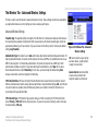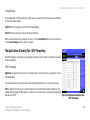
1
®
A Division of Cisco Systems, Inc.
2.4 GHz Wireless-G
802.11g
Broadband Router with 2 Phone Ports
Voice
Installation and Troubleshooting Guide
Model No.
WRTP54G
Wireless-G Broadband Router with 2 Phone Ports
Copyright and Trademarks
Specifications are subject to change without notice. Linksys is a registered trademark or trademark of Cisco Systems,
Inc. and/or its affiliates in the U.S. and certain other countries. Copyright © 2005 Cisco Systems, Inc. All rights
reserved. Other brands and product names are trademarks or registered trademarks of their respective holders.
WARNING: This product contains chemicals, including lead, known to the State of California to cause
cancer, and birth defects or other reproductive harm. Wash hands after handling.
How to Use this Guide
Your guide to the Wireless-G Broadband Router with 2 Phone Ports has been designed to make understanding
networking with the Router easier than ever. Look for the following items when reading this guide:
This exclamation point means there is a caution or warning and is
something that could damage your property or the Router.
This question mark provides you with a reminder about something you
might need to do while using the Router.
This checkmark means there is a note of interest and is something you
should pay special attention to while using the Router.
In addition to these symbols, there are definitions for technical terms that are presented like this:
word: definition.
Also, each figure (diagram, screenshot, or other image) is provided with a figure number and description, like
this:
Figure 0-1: Sample Figure Description
Figure numbers and descriptions can also be found in the “List of Figures” section.
WRTP54G-UG-50329NC JL
Wireless-G Broadband Router with 2 Phone Ports
Wireless-G Broadband Router with 2 Phone Ports
Table of Contents
Chapter 1: Introduction
Welcome
What’s in this Guide?
Chapter 2: Planning Your Wireless Network
1
1
2
5
Network Topology
Ad-Hoc versus Infrastructure Mode
Network Layout
5
5
6
Chapter 3: Getting to Know the Router
7
The Back Panel
The Front Panel
Chapter 4: Connecting the Router
Overview
Connection Instructions
Placement Options
Chapter 5: Configuring the Router
Overview
How to Access the Web-based Utility
The Setup Tab - Basic Setup
The Setup Tab - DDNS
The Setup Tab - MAC Address Clone
The Setup Tab - Advanced Routing
The Wireless Tab - Basic Wireless Settings
The Wireless Tab - Wireless Security
The Wireless Tab - Wireless MAC Filter
7
8
9
9
10
11
13
13
16
17
21
23
24
26
27
30
The Wireless Tab - Advanced Wireless Settings
The Security Tab - Firewall
The Access Restrictions Tab - Filter
The Access Restrictions Tab - Device Access Control
The Applications & Gaming Tab - Port Range Forwarding
The Applications & Gaming Tab - Port Triggering
The Applications & Gaming Tab - UPnP Forwarding
The Applications & Gaming Tab - DMZ
The Applications & Gaming Tab - QoS
The Administration Tab - Management
The Administration Tab - Log
The Administration Tab - Factory Defaults
The Administration Tab - Diagnostics
The Status Tab - Local Network
The Status Tab - Router
The Status Tab - Wireless
The Status Tab - Voice
The Voice Tab
Appendix A: Troubleshooting
Common Problems and Solutions
Frequently Asked Questions
Appendix B: Wireless Security
Security Precautions
Security Threats Facing Wireless Networks
31
33
34
36
37
38
39
42
43
45
46
47
48
49
50
52
53
54
55
55
69
79
79
80
Wireless-G Broadband Router with 2 Phone Ports
Appendix C: Finding the MAC Address and IP
Address for Your Ethernet Adapter
Windows 98 or Me Instructions
Windows 2000 or XP Instructions
For the Router’s Web-based Utility
Appendix D: Windows Help
Appendix E: Glossary
Appendix F: Specifications
Appendix G: Warranty Information
Appendix H: Regulatory Information
Appendix I: Contact Information
Vonage
Linksys
83
83
84
84
85
87
95
97
99
103
103
103
Wireless-G Broadband Router with 2 Phone Ports
List of Figures
Figure 3-1: Back Panel
Figure 3-2: Front Panel
Figure 4-1: Router Connection Diagram
Figure 4-1: Connect the Modem
Figure 4-2: Connect a Telephone
Figure 4-3: Connect a PC
Figure 4-4: Connect the Power
Figure 4-5: Attach the Stand to the Router
Figure 4-6: Measurement between Wall-Mount Slots
Figure 5-1: Router’s IP Address
Figure 5-2: Router Login
Figure 5-3: Setup Tab - Basic Setup (Obtain an
IP automatically)
Figure 5-4: Static IP
Figure 5-5: PPPoE
Figure 5-6: Setup Tab - DDNS (DynDNS.org)
Figure 5-7: Setup Tab - DDNS (TZO.com)
Figure 5-8: Setup Tab - MAC Address Clone
Figure 5-9: Setup Tab - Advanced Routing
Figure 5-10: Routing Table Entry List
Figure 5-11: Wireless Tab - Basic Wireless Settings
Figure 5-12: Wireless Tab - Wireless Security
(WPA-Preshared Key)
Figure 5-13: Wireless Tab - Wireless Security (WPA-RADIUS)
7
8
9
10
10
10
10
11
12
16
16
17
18
19
22
22
23
24
25
26
27
28
Figure 5-14: Wireless Tab - Wireless Security (RADIUS)
Figure 5-15: Wireless Tab - Wireless Security (WEP)
Figure 5-16: Wireless Tab - Wireless MAC Filter
Figure 5-17: MAC Address Filter List
Figure 5-18: Wireless Client MAC List
Figure 5-19: Wireless Tab - Advanced Wireless Settings
Figure 5-20: Security Tab - Firewall
Figure 5-21: Access Restrictions Tab - Filter
Figure 5-22: Filtered MAC Address
Figure 5-23: Access Restrictions Tab - Device Access Control
Figure 5-24: Applications & Gaming Tab - Port
Range Forwarding
Figure 5-25: Applications & Gaming Tab - Port Triggering
Figure 5-26: Applications & Gaming Tab - UPnP Forwarding
Figure 5-27: Applications & Gaming Tab - DMZ
Figure 5-28: Applications & Gaming Tab - QoS
Figure 5-29: QoS - Create Rule
Figure 5-30: Administration Tab - Management
Figure 5-31: Administration Tab - Log
Figure 5-32: Administration Tab - Factory Defaults
Figure 5-33: Administration Tab -Diagnostics
Figure 5-34: Ping Test
Figure 5-35: Traceroute Test
Figure 5-36: Status Tab - Local Network
28
29
30
30
30
31
33
34
34
36
37
38
39
42
43
44
45
46
47
48
48
48
49
Wireless-G Broadband Router with 2 Phone Ports
Figure 5-37: DHCP Active IP Table
Figure 5-38: Status Tab - Router
Figure 5-39: Status Tab - Wireless
Figure 5-40: Wireless Client MAC List
Figure 5-41: Status Tab - Voice
Figure 5-42: Voice Tab
Figure C-1: IP Configuration Screen
Figure C-2: MAC/Adapter Address
Figure C-3: MAC/Physical Address
Figure C-4: MAC Address Clone
Figure C-5: MAC Address Filter
49
50
52
52
53
54
83
83
84
84
84
Wireless-G Broadband Router with 2 Phone Ports
Chapter 1: Introduction
Welcome
Thank you for choosing the Linksys Wireless-G Broadband Router with 2 Phone Ports. This Router will allow you
to network wirelessly better than ever, sharing Internet access, files and fun, easily and securely. Plus, after you
have set up your Vonage service, you can make phone or fax calls using your Internet connection.
wpa (wi-fi protected access): a wireless
security protocol using TKIP (Temporal
Key Integrity Protocol) encryption, which
can be used in conjunction with a
RADIUS server.
How does the Router do all of this? A router is a device that allows access to an Internet connection over a
network. With the Wireless-G Broadband Router with 2 Phone Ports, this access can be shared over the four
switched ports or via the wireless broadcast at either up to 11Mbps for Wireless-B or up to 54Mbps for
Wireless-G. In addition, the WPA standard provides greater security opportunities while the whole network is
protected through NAT technology. All of these security features, as well as full configurability, are accessed
through the easy-to-use browser-based utility.
nat (network address translation): NAT
technology translated IP addresses of a
local area network to a different IP
address for the Internet.
But what does all of this mean?
browser: an application program that
provides a way to look at and interact
with all the information on the World
Wide Web.
Networks are useful tools for sharing Internet access and computer resources. Multiple computers can share
Internet access, so you don’t need more than one high-speed Internet connection. After you set up your Vonage
account, you can also use your Internet access to make Internet phone or fax calls, even while you’re surfing the
Internet. Plus, you can access one printer from different computers and access data located on another
computer’s hard drive. Networks are even used for playing multiplayer video games. All the while, the Router
protects your networks from unauthorized and unwelcome users. So, networks not only are useful in homes and
offices, but also can be fun.
PCs on a wired network create a LAN, or Local Area Network. They are connected with Ethernet cables, which is
why the network is called “wired”.
Chapter 1: Introduction
Welcome
mbps: one million bits per second; a unit
of measurement for data transmission.
lan (local area network): the computers
and networking products that make up
the network in your home or office.
ethernet: an IEEE standard network
protocol that specifies how data is
placed on and retrieved from a common
transmission medium.
1
Wireless-G Broadband Router with 2 Phone Ports
PCs equipped with wireless cards or adapters can communicate without cumbersome cables. By sharing the
same wireless settings, within their transmission radius, they form a wireless network, which is sometimes
called a Wireless Local Area Network (WLAN). The Router bridges wireless networks of both 802.11b and
802.11g standards and wired networks, allowing them to communicate with each other.
To create your network, install and set up the Router. To guide you through the process, Linksys strongly
recommends that you run the Setup Wizard on the Setup CD-ROM. If you prefer to manually set up the Router,
use the instructions in the Quick Installation or this Installation and Troubleshooting Guide to help you. These
instructions should be all you need to get the most out of the Wireless-G Broadband Router with 2 Phone Ports.
802.11b: an IEEE wireless networking
standard that specifies a maximum data
transfer rate of 11Mbps and an operating
frequency of 2.4GHz.
802.11g: an IEEE wireless networking
standard that specifies a maximum data
transfer rate of 54Mbps, an operating
frequency of 2.4GHz, and backward
compatibility with 802.11b devices.
What’s in this Guide?
This guide covers the basic steps for setting up a network with a router. After going through “Chapter 3: Getting
to Know the Router,” most users will only need to use the following chapters:
•
Chapter 4: Connecting the Router
This chapter instructs you on how to connect the Router to your cable or DSL modem, PCs, and telephones
(or fax machines).
•
Chapter 5: Configuring the Router
This chapter explains how to configure the Router using your web browser and the Router’s Web-based
Utility. You will configure the Router using the settings provided by your ISP.
When you’re finished with the basic steps, then you are ready to connect to the Internet.
2
Chapter 1: Introduction
What’s in this Guide?
Wireless-G Broadband Router with 2 Phone Ports
You also have other chapters available for reference:
•
Chapter 1: Introduction
This chapter describes the Router’s applications and this Installation and Troubleshooting Guide.
•
Chapter 2: Planning Your Wireless Network
This chapter describes the basics of wireless networking.
•
Appendix A: Troubleshooting
This appendix describes some possible problems and solutions, as well as frequently asked questions,
regarding installation and use of the Router.
•
Appendix B: Wireless Security
This appendix explains the risks of wireless networking and some solutions to reduce the risks.
•
Appendix C: Finding the MAC Address and IP Address for Your Ethernet Adapter
This appendix instructs you on how to find the MAC address or Ethernet address of your PC’s Ethernet
network adapter.
•
Appendix D: Windows Help
This appendix describes how you can use Windows Help for instructions about networking, such as
installing the TCP/IP protocol.
•
Appendix E: Glossary
This appendix gives a brief glossary of terms frequently used in networking.
•
Appendix F: Specifications
This appendix provides the technical specifications for the Router.
•
Appendix G: Warranty Information
This appendix supplies the warranty information for the Router.
Chapter 1: Introduction
What’s in this Guide?
3
Wireless-G Broadband Router with 2 Phone Ports
• Appendix H: Regulatory Information
This appendix supplies the regulatory information regarding the Router.
•
4
Appendix I: Contact Information
This appendix provides contact information for a variety of Linksys resources, including Technical Support,
as well as Vonage.
Chapter 1: Introduction
What’s in this Guide?
Wireless-G Broadband Router with 2 Phone Ports
Chapter 2: Planning Your Wireless Network
Network Topology
A wireless local area network (WLAN) is exactly like a regular local area network (LAN), except that each
computer in the WLAN uses a wireless device to connect to the network. Computers in a WLAN share the same
frequency channel and SSID, which is an identification name shared by the wireless devices belonging to the
same wireless network.
Ad-Hoc versus Infrastructure Mode
Unlike wired networks, wireless networks have two different modes in which they may be set up: infrastructure
and ad-hoc. An infrastructure configuration is a WLAN and wired LAN communicating to each other through an
access point. An ad-hoc configuration is wireless-equipped computers communicating directly with each other.
Choosing between these two modes depends on whether or not the wireless network needs to share data or
peripherals with a wired network or not.
If the computers on the wireless network need to be accessible by a wired network or need to share a
peripheral, such as a printer, with the wired network computers, the wireless network should be set up in
Infrastructure mode. The basis of Infrastructure mode centers around an access point or wireless router, such as
the Wireless-G Broadband Router with 2 Phone Ports, which serves as the main point of communications in a
wireless network. The Router transmits data to PCs equipped with wireless network adapters, which can roam
within a certain radial range of the Router. You can arrange the Router and multiple access points to work in
succession to extend the roaming range, and you can set up your wireless network to communicate with your
Ethernet hardware as well.
Chapter 2: Planning Your Wireless Network
Network Topology
network: a series of computers or
devices connected for the purpose of
data sharing, storage, and/or
transmission between users.
ssid: your wireless network’s name.
ad-hoc: a group of wireless devices
communicating directly to each other
(peer-to-peer) without the use of an
access point.
infrastructure: a wireless network
that is bridged to a wired network via
an access point.
adapter: a device that adds network
functionality to your PC.
ethernet: IEEE standard network
protocol that specifies how data is
placed on and retrieved from a common
transmission medium.
5
Wireless-G Broadband Router with 2 Phone Ports
If the wireless network is relatively small and needs to share resources only with the other computers on the
wireless network, then the Ad-Hoc mode can be used. Ad-Hoc mode allows computers equipped with wireless
transmitters and receivers to communicate directly with each other, eliminating the need for a wireless router or
access point. The drawback of this mode is that in Ad-Hoc mode, wireless-equipped computers are not able to
communicate with computers on a wired network. And, of course, communication between the wirelessequipped computers is limited by the distance and interference directly between them.
access point: a device that allows
wireless-equipped computers and other
devices to communicate with a wired
network. Also used to expand the range
of a wireless network.
Network Layout
The Wireless-G Broadband Router with 2 Phone Ports has been specifically designed for use with both your
802.11b and 802.11g products. It is compatible with all 802.11b and 802.11g adapters, such as the Notebook
Adapters for your laptop computers, PCI Adapters for your desktop PCs, and USB Adapters when you want to
enjoy USB connectivity. The Broadband Router will also communicate with the Wireless PrintServer and Wireless
Ethernet Bridges.
When you wish to connect your wireless network with your wired network, you can use the Broadband Router’s
four Ethernet network ports. To add more ports, any of the Broadband Router's Ethernet network ports can be
connected to any of Linksys's switches.
With these, and many other, Linksys products, your networking options are limitless. Go to the Linksys website at
www.linksys.com for more information about products that work with the Wireless-G Broadband Router with
2 Phone Ports.
6
Chapter 2: Planning Your Wireless Network
Network Layout
Wireless-G Broadband Router with 2 Phone Ports
Chapter 3: Getting to Know the Router
The Back Panel
The Router’s ports and the Reset button are located on the back panel of the Router.
Figure 3-1: Back Panel
Internet
This Internet port connects to your cable or DSL modem.
Phone1
For your primary Vonage line, the Phone1 port allows you to connect the Router to your
telephone (or fax machine) using an RJ-11 telephone cable (not included).
Phone2
If you have a second Vonage line, the Phone2 port allows you to connect the Router to your
second telephone (or fax machine) using an RJ-11 telephone cable (not included).
Ethernet 1-4
These four Ethernet ports connect to network devices, such as PCs or more switches.
Reset Button
There are two ways to reset the Router's factory defaults. Either press the Reset Button
for five seconds, or restore the defaults from the Router's Web-based Utility.
Power
The Power port is where you will connect the power adapter.
Chapter 3: Getting to Know the Router
The Back Panel
NOTE: The Internet port only
accepts a straight-through
cable. Do NOT connect a
crossover cable to the
Internet port.
NOTE: The Factory Default
feature of the Router’s Webbased Utility is protected by a
password available only from
Vonage. Contact Vonage for
more information.
7
Wireless-G Broadband Router with 2 Phone Ports
The Front Panel
The Router’s LEDs, which inform you about network activities, are located on the front panel.
Figure 3-2: Front Panel
POWER
Blue/Red. The POWER LED lights up blue when the Router is powered on. If the blue LED is
flashing, the Router is booting up or upgrading its firmware. If the LED lights up red, then
disconnect the power, and wait five seconds. Then reconnect the power.
ETHERNET 1-4
Blue. The ETHERNET LED lights up when there is an active connection through the
corresponding port. If the LED is flashing, then there is traffic moving through that port.
WIRELESS
Blue. The WIRELESS LED lights up when there is an active wireless connection. If the LED is
flashing, the Router is sending or receiving data over the wireless network.
PHONE 1-2
Blue. The PHONE LED is solidly lit when a telephone or fax machine has an active or
registered connection to Vonage through the corresponding port (PHONE 1 or 2). It flashes
when the phone is being used or is off the hook.
INTERNET
Blue. The INTERNET LED lights up when the Router is connected to your cable or DSL
modem. If the LED is flashing, the Router is sending or receiving data over the Internet port.
Proceed to “Chapter 4: Connecting the Router.”
8
Chapter 3: Getting to Know the Router
The Front Panel
Wireless-G Broadband Router with 2 Phone Ports
Chapter 4: Connecting the Router
Overview
To begin installation of the Router, you will connect the Router to your PCs, telephone(s) or fax machine(s), and
cable or DSL modem. The following connection diagram illustrates a basic network setup with wired
connections to one desktop PC and telephone and a wireless connection to one notebook PC.
Desktop PC
Internet
Cable/DSL
Modem
Router
NOTE: If you already have a
router in your network, then
replace your existing router with
the Wireless-G Broadband Router
with 2 Phone Ports.
Notebook PC
Telephone
Figure 4-1: Router Connection Diagram
Chapter 4: Connecting the Router
Overview
9
Wireless-G Broadband Router with 2 Phone Ports
Connection Instructions
1. Make sure that all of your hardware is powered off, including the Router, PCs, and broadband modem.
NOTE: Make sure your
telephone is set to its tone
setting (not pulse).
2. Attach the antenna to the Router’s antenna port.
3. Connect your broadband modem’s Ethernet cable to the Router’s Internet port.
4. Connect one end of an Ethernet network cable to one of the numbered ports on the back of the Router.
Connect the other end to an Ethernet port on a network device, e.g., a PC, print server, or switch.
Figure 4-1: Connect the Modem
Repeat this step to connect more PCs or other network devices to the Router.
5. Power on the broadband modem.
Figure 4-2: Connect a Telephone
6. Connect the included power adapter to the Router’s Power port, and then plug the power adapter into an
electrical outlet. The Power LED on the front panel will light up when the adapter is connected properly.
7. Power on your PC(s).
8. Plug a standard telephone into the Router’s Phone1 port.
IMPORTANT: Do not connect the Phone port to a telephone wall jack. Make sure you only connect
a telephone or fax machine to the Phone port. Otherwise, the Router or the telephone wiring in your
home or office may be damaged.
Figure 4-3: Connect a PC
9. If you have a second Vonage phone or fax line, repeat step 8 to connect a telephone or fax machine to the
Router’s Phone2 port.
Figure 4-4: Connect the Power
Proceed to the following section, “Placement Options.”
10
Chapter 4: Connecting the Router
Connection Instructions
Wireless-G Broadband Router with 2 Phone Ports
Placement Options
There are three ways to place the Router. The first way is to place it horizontally on a surface, so it sits on its four
rubber feet. The second way is to stand the Router vertically on a surface. The third way is to mount it on a wall.
The second and third options are explained in further detail below.
Stand Option
1. Line up the center of the Router’s stand with the center of the Router’s labeled edge.
2. Insert the Router into the stand.
Proceed to “Chapter 5: Configuring the Router.”
Figure 4-5: Attach the
Stand to the Router
Chapter 4: Connecting the Router
Placement Options
11
Wireless-G Broadband Router with 2 Phone Ports
Wall-Mount Option
The Router has four wall-mount slots on its bottom panel. The distance between two adjacent slots is
62 mm (2.44 inches).
Before you begin, make sure you have four screws that are size #4—this indicates a diameter measurement of
0.112 inches (2.845 mm).
62 mm
(2.44 inches)
1. Determine where you want to mount the Router.
2. Drill four holes into the wall. Make sure adjacent holes are 62 mm (2.44 inches) apart.
3. Insert a screw into each hole, and leave 5 mm (0.2 inches) of its head exposed.
4. Maneuver the Router so the wall-mount slots line up with the four screws.
5. Place the wall-mount slots over the screws and slide the Router down until the screws fit snugly into the
wall-mount slots.
Proceed to “Chapter 5: Configuring the Router.”
Figure 4-6: Measurement between
Wall-Mount Slots
12
Chapter 4: Connecting the Router
Placement Options
Wireless-G Broadband Router with 2 Phone Ports
Chapter 5: Configuring the Router
Overview
Linksys recommends using the Setup CD-ROM for first-time installation of the Router. If you do not wish to run
the Setup Wizard on the Setup CD-ROM, then you can use the Web-based Utility to configure the Router. For
advanced users, you may configure the Router’s advanced settings through the Web-based Utility.
This chapter will describe each web page on the Utility and each page’s key functions. The Utility can be
accessed via your web browser through use of a computer connected to the Router. For a basic wireless network
setup, most users only have to use the following screens of the Utility:
•
Basic Setup. On the Basic Setup screen, enter the Internet connection settings provided by your ISP. If you do
not have this information, you can call your ISP to request the settings. Once you have the setup information
for your specific type of Internet connection, then you can configure the Router.
•
Management. Click the Administration tab and then the Management tab. The Router’s default user name
and password is admin. To secure the Router, change the User Name and Password from their defaults.
•
Wireless. On the Basic Wireless Settings screen, set the basic configuration for your wireless network.
There are eight main tabs: Setup, Wireless, Security, Access Restrictions, Applications & Gaming, Administration,
Status, and Voice. Additional tabs will be available after you click one of the main tabs.
Chapter 5: Configuring the Router
Overview
13
Wireless-G Broadband Router with 2 Phone Ports
Setup
•
Basic Setup. Enter the Internet connection and network settings on this screen.
•
DDNS. Enable the Router’s Dynamic Domain Name System (DDNS) feature on this screen.
•
MAC Address Clone. If you need to clone a MAC address onto the Router, use this screen.
•
Advanced Routing. On this screen, you can alter firewall, Network Address Translation (NAT), Dynamic
Routing, and Static Routing configurations.
Wireless
•
Basic Wireless Settings. Enter the basic settings for your wireless network on this screen.
•
Wireless Security. Enable and configure the security settings for your wireless network.
•
Wireless MAC Filter. To permit or deny wireless network access for specific devices, set up MAC address
filtering.
•
Advanced Wireless Settings. Advanced users can alter data transmission settings on this screen.
Security
•
14
Firewall. To enable certain types of web filters, use this screen.
Chapter 5: Configuring the Router
Overview
Wireless-G Broadband Router with 2 Phone Ports
Access Restrictions
•
Filter. To block specific users from Internet access, you can set up IP address, port, and MAC address
filtering.
•
Device Access Control. Use this screen to control remote access of the Router.
Applications & Gaming
•
Port Range Forwarding. Set up public services or other specialized Internet applications on your network.
•
Port Triggering. To set up triggered ranges and forwarded ranges for Internet applications, click this tab.
•
DMZ. Click this tab to allow one local user to be exposed to the Internet for use of special-purpose services.
•
QoS. Enable QoS (Quality of Service) to maximize network performance.
Administration
•
Management. On this screen, alter the Router’s user name, password, and UPnP settings.
•
Log. If you want to view or save activity logs, click this tab.
•
Factory Defaults. If you want to reset the Router to its factory default settings, then you will need a password
available only from Vonage. Contact Vonage for more information.
Status
•
Local Network. This provides status information about the local network.
Chapter 5: Configuring the Router
Overview
15
Wireless-G Broadband Router with 2 Phone Ports
• Router. This screen provides status information about the Router.
•
Wireless. This screen provides status information about the Router’s wireless network.
•
Voice. This screen provides status information about your Vonage phone line(s).
Voice
Access to the Voice tab is restricted by Vonage. Contact Vonage for more information.
How to Access the Web-based Utility
To access the Web-based Utility of the Router, launch Internet Explorer or Netscape Navigator, and enter the
Router’s default IP address, 192.168.15.1, in the Address field. Press the Enter key.
Figure 5-1: Router’s IP
Address
The Login screen will appear asking you for your User name and Password. Enter admin in the User Name and
Password fields. Then click the Log In button. Click the Cancel button to exit the Login screen.
Make the necessary changes through the Utility. When you have finished making changes to a screen, click the
Save Settings button to save the changes, or click the Cancel Changes button to undo your changes. Help
information is shown on the right-hand side of a screen. For additional help on a tab, click More.
Figure 5-2: Router Login
16
Chapter 5: Configuring the Router
How to Access the Web-based Utility
Wireless-G Broadband Router with 2 Phone Ports
The Setup Tab - Basic Setup
The Basic Setup screen is the first screen you see when you access the Web-based Utility.
Internet Setup
The Internet Setup section configures the Router for your Internet connection type. This information can be
obtained from your ISP.
Internet Connection Type
The Router supports three connection types: Obtain an IP automatically, Static IP, and PPPoE. Each Basic Setup
screen and available features will differ depending on what kind of connection type you select.
Obtain an IP automatically
By default, the Router’s Internet Connection Type is set to Obtain an IP automatically, and it should be
used only if your ISP supports DHCP or you are connecting through a dynamic IP address.
Chapter 5: Configuring the Router
The Setup Tab - Basic Setup
Figure 5-3: Setup Tab - Basic Setup
(Obtain an IP automatically)
17
Wireless-G Broadband Router with 2 Phone Ports
Static IP
If you are required to use a permanent IP address, then select Static IP.
IP Address. This is the IP address that the Router has, when seen from the Internet. Your ISP will provide
you with the IP Address you need to specify here.
Subnet Mask. This is the Router’s Subnet Mask, as seen by external users on the Internet (including your
ISP). Your ISP will provide you with the Subnet Mask.
Gateway. Your ISP will provide you with the Default Gateway Address.
DNS 1-3. Your ISP will provide you with at least one DNS (Domain Name System) Server IP Address.
WINS. The Windows Internet Naming Service (WINS) converts NetBIOS names to IP addresses. If you use a
WINS server, enter that server’s IP address here. Otherwise, leave this field blank.
PPPoE
Some DSL-based ISPs use PPPoE (Point-to-Point Protocol over Ethernet) to establish Internet connections for
end-users. If you use a DSL line, check with your ISP to see if they use PPPoE. If they do, you will have to
enable it.
User Name and Password. Enter the User Name and Password provided by your ISP.
Connect on Demand and Idle Timeout. You can configure the Router to cut the Internet connection after it
has been inactive for a specific period of time (Idle Timeout). If your Internet connection has been terminated
due to inactivity, Connect on Demand enables the Router to automatically re-establish your connection as
soon as you attempt to access the Internet again. If you wish to activate Connect on Demand, click the radio
18
Figure 5-4: Static IP
static ip address: a fixed address
assigned to a computer or device
connected to a network.
subnet mask: an address code that
determines the size of the network.
default gateway: a device that forwards
Internet traffic from your local area
network.
pppoe: a type of broadband connection
that provides authentication (username
and password) in addition to data
transport.
Chapter 5: Configuring the Router
The Setup Tab - Basic Setup
Wireless-G Broadband Router with 2 Phone Ports
button. If you want your Internet connection to remain on at all times, enter 0 in the Idle Timeout field.
Otherwise, enter the number of minutes you want to have elapsed before your Internet access disconnects.
Keep Alive and Redial Period. This option keeps your Internet access connected indefinitely, even when it
sits idle. If you select this option, the Router will periodically check your Internet connection. If the
connection is down, then the Router will automatically re-establish the connection. To use this option, click
the radio button next to Keep Alive. The default Redial Period is 30 seconds.
When you are finished, click the Save Settings button. Then click the Status tab, and click the Connect
button to start the connection.
Optional Settings
Some of these settings may be required by your ISP. Verify with your ISP before making any changes.
Figure 5-5: PPPoE
NOTE: For DSL users, if you
need to enable PPPoE support,
remember to remove any PPPoE
applications that are installed
on your PCs.
Host Name and Domain Name. These fields allow you to supply a host and domain name for the Router. Some
ISPs require these names as identification. You may have to check with your ISP to see if your broadband
Internet service has been configured with a host and domain name. In most cases, leaving these fields blank will
work.
MTU. The MTU (Maximum Transmission Unit) setting specifies the largest packet size permitted for network
transmission. Select Auto to have the Router automatically select the MTU value, or select Manual and enter the
value desired. It is recommended that you leave this value in the 1200 to 1500 range. For two Internet connection
types, Obtain an IP automatically and Static IP, the MTU’s default value is 1500. For PPPoE, the MTU’s default
value is 1492.
packet: a unit of data sent over
a network.
Network Setup
The Network Setup section allows you to change the Router’s local network settings.
Chapter 5: Configuring the Router
The Setup Tab - Basic Setup
19
Wireless-G Broadband Router with 2 Phone Ports
Router IP
The values for the Router’s Local IP Address and Subnet Mask are shown here. In most cases, keeping the
default values will work.
Local IP Address. The default value is 192.168.15.1.
Subnet Mask. The default value is 255.255.255.0.
Network Address Server Settings (DHCP)
These settings allow you to configure the Router’s Dynamic Host Configuration Protocol (DHCP) server function.
The Router can be used as a DHCP server for your network. A DHCP server automatically assigns an IP address
to each computer on your network. Unless you already have one, it is highly recommended that you leave the
Router enabled as a DHCP server.
Local DHCP Server. DHCP is enabled by factory default. If you already have a DHCP server on your network, set
the Router’s DHCP option to Disable. If you disable DHCP, remember to assign a static IP address to the Router.
Start IP Address. Enter a value for the DHCP server to start with when issuing IP addresses. Because the
default IP address for the Router is 192.168.15.1, the Start IP Address must be 192.168.15. 101 or greater, but
smaller than 192.168.15.254. The default Start IP Address is 192.168.15.100.
Number of Address (Optional). Enter the maximum number of PCs that you want the DHCP server to assign IP
addresses to. This number cannot be greater than 253. The default is 50.
DHCP Address Range. The range of DHCP addresses is displayed here.
20
Chapter 5: Configuring the Router
The Setup Tab - Basic Setup
Wireless-G Broadband Router with 2 Phone Ports
Client Lease Time. The Client Lease Time is the amount of time a network user will be allowed connection to the
Router with their current dynamic IP address. Enter the amount of time, in minutes, that the user will be “leased” dynamic ip address: a temporary IP
this dynamic IP address. After the dynamic IP address has expired, the user will be automatically assigned a new address assigned by a DHCP server.
dynamic IP address. The default is 0 minutes, which means one day.
WINS. The Windows Internet Naming Service (WINS) converts NetBIOS names to IP addresses. If you use a WINS
server, enter that server’s IP address here. Otherwise, leave this field blank.
Time Setting
Change the time zone in which your network functions from this pull-down menu. To use the Router’s daylight
savings feature, click the Automatically adjust clock for daylight saving changes checkbox.
When you have finished making changes to this screen, click the Save Settings button to save the changes, or
click the Cancel Changes button to undo your changes.
NOTE: To test your settings, connect to the Internet now.
The Setup Tab - DDNS
The Router offers a Dynamic Domain Name System (DDNS) feature. DDNS lets you assign a fixed host and
domain name to a dynamic Internet IP address. It is useful when you are hosting your own website, FTP server,
or other server behind the Router.
ddns: allows the hosting of a website, FTP
server, or e-mail server with a fixed
domain name (e.g., www.xyz.com) and a
dynamic IP address.
Before you can use this feature, you need to sign up for DDNS service at one of two DDNS service providers,
DynDNS.org or TZO.com. If you do not want to use this feature, keep the default setting, Disable.
Chapter 5: Configuring the Router
The Setup Tab - DDNS
21
Wireless-G Broadband Router with 2 Phone Ports
DDNS
DDNS Service. If you use DynDNS.org, then select DynDNS.org. If you use TZO, then select TZO.com. The
features available on the DDNS screen will vary, depending on which DDNS service provider you use.
DynDNS.org
User Name, Password, and Host Name. Enter the User Name, Password, and Host Name of the account
you set up with DynDNS.org.
Internet IP Address. The Router’s current Internet IP Address is displayed here. Because it is dynamic, this
will change.
Figure 5-6: Setup Tab - DDNS
(DynDNS.org)
Status. The status of the DDNS service connection is displayed here.
TZO.com
E-mail Address, Password, and Domain Name. Enter the Email Address, Password, and Domain Name
of the service you set up with TZO.
Internet IP Address. The Router’s current Internet IP Address is displayed here. Because it is dynamic, this
will change.
Status. The status of the DDNS service connection is displayed here.
When you have finished making changes to this screen, click the Update button to save the changes, or
click the Cancel Changes button to undo your changes.
22
Figure 5-7: Setup Tab - DDNS (TZO.com)
Chapter 5: Configuring the Router
The Setup Tab - DDNS
Wireless-G Broadband Router with 2 Phone Ports
The Setup Tab - MAC Address Clone
A MAC address is a 12-digit code assigned to a unique piece of hardware for identification, like a social security
number. Some ISPs will require you to register a MAC address in order to access the Internet. If you do not wish
to re-register the MAC address with your ISP, you may assign the MAC address you have currently registered
with your ISP to the Router with the MAC Address Clone feature.
MAC Clone
MAC Clone Service. To use MAC address cloning, select Enable.
MAC Address. Enter the MAC Address registered with your ISP. Then click the Save Settings button.
Clone. If you want to clone the MAC address of the PC you are currently using to configure the Router, then click
the Clone button. The Router will automatically detect your PC’s MAC address, so you do NOT have to call your
ISP to change the registered MAC address to the Router’s MAC address. It is recommended that the PC
registered with the ISP is used to open the MAC Address Clone screen.
Figure 5-8: Setup Tab MAC Address Clone
mac address: the unique address that a
manufacturer assigns to each networking
device.
When you have finished making changes to this screen, click the Save Settings button to save the changes, or
click the Cancel Changes button to undo your changes.
Chapter 5: Configuring the Router
The Setup Tab - MAC Address Clone
23
Wireless-G Broadband Router with 2 Phone Ports
The Setup Tab - Advanced Routing
The Advanced Routing screen allows you to configure the firewall, Network Address Translation (NAT), dynamic
routing, and static routing settings.
Advanced Routing
Firewall & NAT. The Stateful Packet Inspection (SPI) firewall reviews data packets entering your network. NAT
is a security feature that enables the Router to translate IP addresses of your local area network to a different IP
address for the Internet. These features are enabled by default. To disable the firewall and NAT, click the
Disable radio button. (When NAT is disabled, the DHCP server feature is also disabled.)
Dynamic Routing. This feature enables the Router to automatically adjust to physical changes in the network’s
layout and exchange routing tables with the other router(s). The Router determines the network packets’ route
based on the fewest number of hops between the source and the destination. To enable Dynamic Routing, click
the Enable radio button. To disable this feature, click the Disable radio button.
Figure 5-9: Setup Tab Advanced Routing
Transmit RIP Version. To use dynamic routing for transmission of network data, select the protocol you want,
RIP1 v1, RIP1 v1 Compatible, or RIP v2.
Static Routing. Use this feature to set up a static router between the Router and another network. (A static route
is a pre-determined pathway that network information must travel to reach a specific host or network.) To create
a static route, alter the following settings:
Select Entry. Select the number of the static route from the drop-down menu. The Router supports up to 20
static route entries.
Destination LAN IP. The Destination LAN IP Address is the address of the remote network or host to which
you want to assign a static route. Enter the IP address of the host for which you wish to create a static route.
24
Chapter 5: Configuring the Router
The Setup Tab - Advanced Routing
Wireless-G Broadband Router with 2 Phone Ports
Subnet Mask. The Subnet Mask determines which portion of a Destination IP address is the network
portion, and which portion is the host portion.
Gateway. This is the IP address of the gateway device that allows for contact between the Router and the
remote network or host.
Hop Count. This determines the maximum number of steps between network nodes that data packets will
travel. A node is any device on the network, such as PCs, print servers, routers, etc.
Interface. Select Local or Internet, depending on the location of the static route’s final destination.
Delete Entry. If you need to delete a route, select its number from the drop-down menu, and click the Delete
Entry button.
Show Routing Table. Click the Show Routing Table button to open a screen displaying how data is routed
through your local network. For each route, the Destination LAN IP address, Default Gateway, Subnet Mask,
Flags, Metric, Ref (Reference), User, and Interface are displayed. Click the Refresh button to update the
information.
When you have finished making changes to this screen, click the Save Settings button to save the changes, or
click the Cancel Changes button to undo your changes.
Figure 5-10: Routing Table Entry List
Chapter 5: Configuring the Router
The Setup Tab - Advanced Routing
25
Wireless-G Broadband Router with 2 Phone Ports
The Wireless Tab - Basic Wireless Settings
The basic settings for wireless networking are set on this screen.
Wireless Settings
Wireless Network Mode. From this drop-down menu, you can select the wireless standards running on your
network. If you have both 802.11g and 802.11b devices in your network, keep the default setting, Mixed. If you
have only 802.11g devices, select G-Only. If you have only 802.11b devices, select B-Only. If you do not have
any 802.11g and 802.11b devices in your network, select Disable.
Figure 5-11: Wireless Tab - Basic
Wireless Settings
Wireless Network Name (SSID). The SSID is the network name shared among all points in a wireless network.
The SSID must be identical for all devices in the wireless network. It is case-sensitive and must not exceed 32
characters (use any of the characters on the keyboard). Make sure this setting is the same for all points in your
wireless network. For added security, you should change the default SSID (linksys) to a unique name.
Wireless Channel. Select the appropriate channel from the list provided to correspond with your network
settings. All devices in your wireless network must be broadcast on the same channel in order to function
correctly.
Wireless SSID Broadcast. When wireless clients survey the local area for wireless networks to associate with,
they will detect the SSID broadcast by the Router. To broadcast the Router's SSID, keep the default setting,
Enable. If you do not want to broadcast the Router's SSID, then select Disable.
When you have finished making changes on this screen, click the Save Settings button to save the changes, or
click the Cancel Changes button to undo your changes.
26
Chapter 5: Configuring the Router
The Wireless Tab - Basic Wireless Settings
Wireless-G Broadband Router with 2 Phone Ports
The Wireless Tab - Wireless Security
The Wireless Security settings configure the security of your wireless network. If you do not want to use wireless
security, keep the default, Disabled. There are four wireless security mode options supported by the Router:
WPA Pre-Shared Key, WPA RADIUS, RADIUS, and WEP. (WPA stands for Wi-Fi Protected Access, which is a
security standard stronger than WEP encryption. WEP stands for Wired Equivalent Privacy, while RADIUS stands
for Remote Authentication Dial-In User Service.) These three are briefly discussed here. For detailed instructions
on configuring wireless security for the Router, proceed to “Appendix B: Wireless Security.”
Wireless Security
WPA-Preshared Key. Select TKIP or AES from the WPA Algorithm drop-down menu. Enter a WPA Shared Key of
8-32 characters. Then enter the Group Key Renewal period, which instructs the Router how often it should
change the encryption keys.
wpa (wi-fi protected access): a
wireless security protocol using TKIP
(Temporal Key Integrity Protocol)
encryption, which can be used in
conjunction with a RADIUS server.
wep (wired equivalent privacy): a
method of encrypting network data
transmitted on a wireless network for
greater security.
When you have finished making changes on this screen, click the Save Settings button to save the changes, or
click the Cancel Changes button to undo your changes.
Figure 5-12: Wireless Tab - Wireless
Security (WPA-Preshared Key)
Chapter 5: Configuring the Router
The Wireless Tab - Wireless Security
27
Wireless-G Broadband Router with 2 Phone Ports
WPA-RADIUS. This option features WPA used in coordination with a RADIUS server. (This should only be used
when a RADIUS server is connected to the Router.) Select TKIP or AES from the WPA Algorithm drop-down
menu. Enter the RADIUS server’s IP address and port number, along with the Shared Key, which is the key
shared between the Router and the server. Last, enter the Key Renewal Timeout period, which instructs the
Router how often it should change the encryption keys.
When you have finished making changes on this screen, click the Save Settings button to save the changes, or
click the Cancel Changes button to undo your changes.
Figure 5-13: Wireless Tab - Wireless
Security (WPA-RADIUS)
radius: a protocol that uses an
authentication server to control
network access.
RADIUS. This option features WEP encryption used in coordination with a RADIUS server. (This should only be
used when a RADIUS server is connected to the Router.) Enter the RADIUS server’s IP address and port number,
along with the Shared Key, which is the key shared between the Router and the server.
To indicate which WEP key to use, select the appropriate Default Transmit Key number. Select a level of WEP
encryption, 64 bits 10 hex digits or 128 bits 26 hex digits. If you want to use a Passphrase, then enter it in
the Passphrase field and click the Generate button. If you want to enter the WEP key(s) manually, then enter it
in the Key 1-4 field(s).
When you have finished making changes on this screen, click the Save Settings button to save the changes, or
click the Cancel Changes button to undo your changes.
Figure 5-14: Wireless Tab - Wireless
Security (RADIUS)
28
Chapter 5: Configuring the Router
The Wireless Tab - Wireless Security
Wireless-G Broadband Router with 2 Phone Ports
WEP. WEP is a basic encryption method, which is not as secure as WPA. To indicate which WEP key to use,
select the appropriate Default Transmit Key number. Select a level of WEP encryption, 64 bits 10 hex digits or
128 bits 26 hex digits. If you want to use a Passphrase, then enter it in the Passphrase field and click the
Generate button. If you want to enter the WEP key(s) manually, then enter it in the Key 1-4 field(s).
When you have finished making changes on this screen, click the Save Settings button to save the changes, or
click the Cancel Changes button to undo your changes.
Figure 5-15: Wireless Tab - Wireless
Security (WEP)
Chapter 5: Configuring the Router
The Wireless Tab - Wireless Security
29
Wireless-G Broadband Router with 2 Phone Ports
The Wireless Tab - Wireless MAC Filter
Wireless MAC Filter
Wireless MAC Filter. If you want to filter wireless access by MAC address, select Enable. Otherwise, select
Disable.
Click Prevent to block access for the designated computers, or click Permit only to permit access for the
designated computers. Click the Update Filter List button, and the Mac Address Filter List screen will appear.
Enter the MAC addresses of the computers you want to designate. To see a list of MAC addresses for wireless
computers or clients, click the Wireless Client MAC List button.
Figure 5-16: Wireless Tab - Wireless
MAC Filter
The Wireless Client MAC List screen will list Client Host Names, IP Addresses, and MAC Addresses for your
wireless devices. Click the Refresh button to get the most up-to-date information. To add a specific computer to
the Mac Address Filter List, click the Enable MAC Filter checkbox and then the Update Filter List button. Click
the Close button to return to the MAC Address Filter List screen.
On the MAC Address Filter List screen, click the Save Settings button to save this list, or click the Cancel
Changes button to remove your entries.
When finished making your changes on this tab, click the Save Settings button to save these changes, or click
the Cancel Changes button to undo your changes.
Figure 5-17: MAC Address Filter List
Figure 5-18: Wireless Client MAC List
30
Chapter 5: Configuring the Router
The Wireless Tab - Wireless MAC Filter
Wireless-G Broadband Router with 2 Phone Ports
The Wireless Tab - Advanced Wireless Settings
This tab is used to set up the Router’s advanced wireless functions. These settings should only be adjusted by
an expert administrator as incorrect settings can reduce wireless performance.
Advanced Wireless Settings
Preamble Type. The preamble defines the length of the CRC block for communication between the Router and
the roaming wireless adapters. (High network traffic areas should use the shorter preamble type.) Select the
appropriate preamble type for your network. If you are not sure which setting to select, then keep the default
setting, Long Preamble.
Authentication Type. The default is set to Auto, which allows Open System and Shared Key authentication. For
Open System authentication, the sender and the recipient do not use a WEP key for authentication but can use
WEP for data encryption. For Shared Key authentication, the sender and recipient use a WEP key for both
authentication and data encryption. To only allow Open System authentication, select Open. To only allow
Shared Key authentication, select Shared Key. In most cases, you should keep the default setting, Auto,
because some clients cannot be configured for Shared Key.
CTS Protection Mode. CTS (Clear-To-Send) Protection Mode function boosts the Router’s ability to catch all
Wireless-G transmissions but will severely decrease performance. Keep the default setting, Auto, so the Router
can use this feature as needed, when the Wireless-G products are not able to transmit to the Router in an
environment with heavy 802.11b traffic.
Figure 5-19: Wireless Tab - Advanced
Wireless Settings
cts (clear to send): a signal sent by
a wireless device, signifying that it
is ready to receive data.
beacon interval: data transmitted
on your wireless network that
keeps the network synchronized.
CTS Protection Type. CTS Protection Type specifies the type of traffic covered by the CTS Protection Mode.
Select CTS-only or RTS-CTS from the drop-down menu. If you are not sure which setting to select, then keep
the default setting, CTS-only.
Chapter 5: Configuring the Router
The Wireless Tab - Advanced Wireless Settings
31
Wireless-G Broadband Router with 2 Phone Ports
Power Level. You can adjust the output power of the Router to get the appropriate coverage for your wireless
network. Select the percentage of power you need for your environment. If you are not sure which setting to
select, then keep the default setting, Full.
Beacon Interval. The Beacon Interval value indicates the frequency interval of the beacon. A beacon is a packet
broadcast by the Router to synchronize the wireless network. The default value is 100.
DTIM Interval. This indicates the interval of the Delivery Traffic Indication Message (DTIM). A DTIM field is a
countdown field informing clients of the next window for listening to broadcast and multicast messages. When
the Router has buffered broadcast or multicast messages for associated clients, it sends the next DTIM with a
DTIM Interval value. Its clients hear the beacons and awaken to receive the broadcast and multicast messages.
The default value is 3.
dtim: a message included in data
packets that can increase wireless
efficiency.
Fragmentation Length. This value specifies the maximum size for a packet before data is fragmented into
multiple packets. If you experience a high packet error rate, you may slightly increase the Fragmentation
Threshold. Setting the Fragmentation Length too low may result in poor network performance. Only minor
reduction of the default value is recommended. In most cases, it should remain at its default value of 2346.
fragmentation: breaking a packet
into smaller units when
transmitting over a network
medium that cannot support the
original size of the packet.
RTS Threshold. Should you encounter inconsistent data flow, only minor reduction of the default value, 2347, is
recommended. If a network packet is smaller than the preset RTS threshold size, the RTS/CTS mechanism will
not be enabled. The Router sends Request to Send (RTS) frames to a particular receiving station and negotiates
the sending of a data frame. After receiving an RTS, the wireless station responds with a Clear to Send (CTS)
frame to acknowledge the right to begin transmission. In most cases, keep the default value, 2347.
rts (request to send): a networking
method of coordinating large packets
through the RTS Threshold setting.
When you have finished making changes on this screen, click the Save Settings button to save the changes, or
click the Cancel Changes button to undo your changes.
32
Chapter 5: Configuring the Router
The Wireless Tab - Advanced Wireless Settings
Wireless-G Broadband Router with 2 Phone Ports
The Security Tab - Firewall
When you click the Security tab, you will see the Firewall screen. You can use this screen to enable a variety of
web filters, which will enhance the firewall protecting your network.
Web Filters
Filter Proxy. Use of WAN proxy servers may compromise the Gateway's security. Denying Filter Proxy will
disable access to any WAN proxy servers. To enable proxy filtering, click the checkbox.
Figure 5-20: Security Tab - Firewall
Filter Java Applets. Java is a programming language for websites. If you deny Java Applets, you run the risk of
not having access to Internet sites created using this programming language. To enable Java Applet filtering,
click the checkbox.
Filter Pop-Ups. When you use the Internet, sometimes unwanted pop-up screens may appear on your screen.
To enable pop-up filtering, click the checkbox.
Filter Cookies. A cookie is data stored on your computer and used by Internet sites when you interact with
them. To enable cookie filtering, click the checkbox.
Filter ActiveX. ActiveX is a programming language for websites. If you deny ActiveX, you run the risk of not
having access to Internet sites created using this programming language. To enable ActiveX filtering, click the
checkbox.
When you have finished making changes on this screen, click the Save Settings button to save the changes, or
click the Cancel Changes button to undo your changes.
Chapter 5: Configuring the Router
The Security Tab - Firewall
33
Wireless-G Broadband Router with 2 Phone Ports
The Access Restrictions Tab - Filter
Filters can block specific internal users from accessing the Internet, anonymous Internet requests, and/or
multicasting.
Filter IP Address Range
You can create up to five different IP Address filters. To set up a filter, enter the IP address you wish to filter in
the field provided. Users who have filtered IP addresses will not be able to access the Internet at all.
Filter Port Range
You can create up to five different Port Range filters. To filter users by network port number, select the protocol
you want to filter, TCP, UDP, or Both, from the Protocol drop-down menu. Enter the port numbers you want to
filter in the Start and End fields. Users connected to the Router will no longer be able to access any port number
listed there.
Figure 5-21: Access Restrictions Tab Filter
Filter MAC Address
This feature blocks computers with specific MAC addresses from going out to the Internet. For information on
obtaining a MAC address, go to “Appendix C: Finding the MAC Address and IP Address for Your Ethernet
Adapter.” To set the MAC filter, click the Edit MAC Filter Setting button.
Edit MAC Filter Setting. Click the Edit MAC Filter Setting button. Select the range of MAC address entries in
the drop-down box. In each mac field, enter the MAC address you want to filter. Click the Apply button before
closing the window. To cancel changes, click the Undo button.
Figure 5-22: Filtered MAC Address
34
Chapter 5: Configuring the Router
The Access Restrictions Tab - Filter
Wireless-G Broadband Router with 2 Phone Ports
Block WAN Requests
Use these features to enhance your network’s security and filter multicasting.
Block Anonymous Internet Requests. This keeps your network from being “pinged” or detected and
reinforces your network security by hiding your network ports, so it is more difficult for intruders to work their
way into your network. Select Enabled to block anonymous Internet requests, or Disabled to allow anonymous
Internet requests.
Filter Multicast. Multicasting allows for multiple transmissions to specific recipients at the same time. If
multicasting is permitted, then the Router will allow IP multicast packets to be forwarded to the appropriate
computers. Select Enabled to filter multicasting, or Disabled to disable this feature.
When you have finished making changes to this screen, click the Save Settings button to save the changes, or
click the Cancel Changes button to undo your changes.
Chapter 5: Configuring the Router
The Access Restrictions Tab - Filter
35
Wireless-G Broadband Router with 2 Phone Ports
The Access Restrictions Tab - Device Access Control
Use this screen to control local and remote access to the Router’s management ports via different services.
Access Control
Enable Access Control. If you want to control access to the Router’s management ports via the services listed
below, click the checkbox. For each service, make sure the appropriate checkbox is checked if you want to
allow local or remote access. Make sure the appropriate checkbox is not checked if you want to block local or
remote access.
If the Access Control feature is disabled, then access is permitted within the local network but blocked for the
Internet.
Figure 5-23: Access Restrictions Tab Device Access Control
NOTE: When a checkbox
for a service is checked,
access is enabled. When a
checkbox is unchecked,
access is denied.
Service Name. You can control access for five services: Telnet, Web, FTP, TFTP, and Secure Shell (SSH).
WAN. If you want to block WAN (Internet) access for a service, make sure the appropriate checkbox is
unchecked. If you want to allow access, then make sure the appropriate checkbox is checked.
LAN. If you want to block local access for a service, make sure the appropriate checkbox is unchecked. If you
want to allow access, then make sure the appropriate checkbox is checked.
IP Access List. Specify the IP addresses that are allowed to remotely access the Router. If you want to delete an
IP address, select it and then click the Delete checkbox.
New IP. To add an IP address, enter it in the field provided, and then click the Add checkbox.
When you have finished making changes to this screen, click the Save Settings button to save the changes, or
click the Cancel Changes button to undo your changes.
36
Chapter 5: Configuring the Router
The Access Restrictions Tab - Device Access Control
Wireless-G Broadband Router with 2 Phone Ports
The Applications & Gaming Tab - Port Range Forwarding
When you click the Applications & Gaming tab, you will see the Port Range Forwarding screen. Port Range
Forwarding sets up public services on your network, such as web servers, ftp servers, e-mail servers, or other
specialized Internet applications. (Specialized Internet applications are any applications that use Internet
access to perform functions such as videoconferencing or online gaming. Some Internet applications may not
require any forwarding.) When users send this type of request to your network via the Internet, the Router will
forward those requests to the appropriate PC.
Before using forwarding, you should assign a static IP address to the designated PC.
If you need to forward all ports to one PC, click the DMZ tab.
Port Range Forwarding
Port Range
To add a server using Port Range Forwarding, complete the following fields:
Application. Enter the name of the application.
Start and End. Enter the number or range of external port(s) used by the server or Internet application. Check
with the Internet application software documentation for more information.
Protocol. Select the protocol TCP or UDP, or select Both.
IP Address. Enter the IP address of the server that you want the Internet users to be able to access. To find the
IP address, go to “Appendix C: Finding the MAC Address and IP Address for Your Ethernet Adapter.”
Chapter 5: Configuring the Router
The Applications & Gaming Tab - Port Range Forwarding
Figure 5-24: Applications & Gaming Tab Port Range Forwarding
tcp: a network protocol for transmitting
data that requires acknowledgement from
the recipient of data sent.
udp: a network protocol for transmitting
data that does not require
acknowledgement from the recipient of
the data that is sent.
ip (internet protocol): a protocol used to
send data over a network.
ip address: the address used to identify a
computer or device on a network.
37
Wireless-G Broadband Router with 2 Phone Ports
Enable. Check the Enable box to enable the services you have defined. Port Range Forwarding will not function
if the Enabled button is left unchecked. This is disabled (unchecked) by default.
When you have finished making changes to this screen, click the Save Settings button to save the changes, or
click the Cancel Changes button to undo your changes.
The Applications & Gaming Tab - Port Triggering
The Port Triggering screen allows the Router to watch outgoing data for specific port numbers. The IP address
of the computer that sends the matching data is remembered by the Router, so that when the requested data
returns through the Router, the data is pulled back to the proper computer by way of IP address and port
mapping rules.
Port Triggering
Application. Enter the application name of the trigger.
Triggered Range
For each application, list the triggered port number range. Check with the Internet application documentation for
the port number(s) needed.
Figure 5-25: Applications & Gaming Tab Port Triggering
Start Port. Enter the starting port number of the Triggered Range.
End Port. Enter the ending port number of the Triggered Range.
38
Chapter 5: Configuring the Router
The Applications & Gaming Tab - Port Triggering
Wireless-G Broadband Router with 2 Phone Ports
Forwarded Range
For each application, list the forwarded port number range. Check with the Internet application documentation
for the port number(s) needed.
Start Port. Enter the starting port number of the Forwarded Range.
End Port. Enter the ending port number of the Forwarded Range.
When you have finished making changes to this screen, click the Save Settings button to save the changes, or
click the Cancel Changes button to undo your changes.
The Applications & Gaming Tab - UPnP Forwarding
The UPnP Forwarding screen displays preset application settings as well as options to customize port services
for other applications.
UPnP Forwarding
Application. Ten applications are preset. For custom applications, enter the name of your application in one of
the available fields.
The preset applications are among the most widely used Internet applications. They include the following:
FTP (File Transfer Protocol). A protocol used to transfer files over a TCP/IP network (Internet, UNIX, etc.). For
example, after developing the HTML pages for a website on a local machine, they are typically uploaded to the
Figure 5-26: Applications & Gaming Tab web server using FTP.
UPnP Forwarding
Chapter 5: Configuring the Router
The Applications & Gaming Tab - UPnP Forwarding
39
Wireless-G Broadband Router with 2 Phone Ports
Telnet. A terminal emulation protocol commonly used on Internet and TCP/IP-based networks. It allows a user at
a terminal or computer to log onto a remote device and run a program.
SMTP (Simple Mail Transfer Protocol). The standard e-mail protocol on the Internet. It is a TCP/IP protocol that
defines the message format and the message transfer agent (MTA), which stores and forwards the mail.
DNS (Domain Name System). The way that Internet domain names are located and translated into IP addresses.
A domain name is a meaningful and easy-to-remember “handle” for an Internet address.
TFTP (Trivial File Transfer Protocol). A version of the TCP/IP FTP protocol that has no directory or password
capability.
Finger. A UNIX command widely used on the Internet to find out information about a particular user, such as a
telephone number, whether the user is currently logged on, and the last time the user was logged on. The person
being “fingered” must have placed his or her profile on the system in order for the information to be available.
Fingering requires entering the full user@domain address.
HTTP (HyperText Transport Protocol). The communications protocol used to connect to servers on the World Wide
Web. Its primary function is to establish a connection with a web server and transmit HTML pages to the client
web browser.
POP3 (Post Office Protocol 3). A standard mail server commonly used on the Internet. It provides a message
store that holds incoming e-mail until users log on and download it. POP3 is a simple system with little
selectivity. All pending messages and attachments are downloaded at the same time. POP3 uses the SMTP
messaging protocol.
NNTP (Network News Transfer Protocol). The protocol used to connect to Usenet groups on the Internet. Usenet
newsreaders support the NNTP protocol.
40
Chapter 5: Configuring the Router
The Applications & Gaming Tab - UPnP Forwarding
Wireless-G Broadband Router with 2 Phone Ports
SNMP (Simple Network Management Protocol). A widely used network monitoring and control protocol. Data is
passed from SNMP agents, which are hardware and/or software processes reporting activity in each network
device (hub, router, bridge, etc.) to the workstation console used to oversee the network. The agents return
information contained in a MIB (Management Information Base), which is a data structure that defines what is
obtainable from the device and what can be controlled (turned off, on, etc.).
Ext. Port. Enter the number of the external port used by the server in the Ext. Port column. Check with the
Internet application documentation for more information.
TCP or UDP. Select the protocol UDP or TCP for each application. You cannot select both protocols.
Int. Port. Enter the number of the internal port used by the server in the Int. Port column. Check with the Internet
application software documentation for more information.
IP Address. Enter the IP address of the server that you want the Internet users to be able to access. To find the
IP address, go to “Appendix C: Finding the MAC Address and IP Address for Your Ethernet Adapter.”
Enabled. Check the Enabled box to enable the service you have defined. UPnP Forwarding will not function if
the Enabled button is left unchecked. This is disabled (unchecked) by default.
When you have finished making changes to this screen, click the Save Settings button to save the changes, or
click the Cancel Changes button to undo your changes. Help information is shown on the right-hand side of a
screen. For additional information, click More.
Chapter 5: Configuring the Router
The Applications & Gaming Tab - UPnP Forwarding
41
Wireless-G Broadband Router with 2 Phone Ports
The Applications & Gaming Tab - DMZ
The DMZ screen allows one local user to be exposed to the Internet for use of a special-purpose service such as
Internet gaming and videoconferencing. DMZ hosting forwards all the ports at the same time to one PC. The
Port Range Forwarding is more secure because it only opens the ports you want to have opened, while DMZ
hosting opens all the ports of one computer, exposing the computer to the Internet.
Any PC whose port is being forwarded must have its DHCP client function disabled and should have a new static
IP address assigned to it because its IP address may change when using the DHCP function.
DMZ
Figure 5-27: Applications & Gaming Tab DMZ
DMZ. To use this feature, select Enabled. To disable DMZ hosting, select Disabled.
DMZ Host IP Address. To expose one PC, enter the computer’s IP address. To get the IP address of a computer,
refer to “Appendix C: Finding the MAC Address and IP Address for Your Ethernet Adapter.” Deactivate DMZ by
entering a 0 in the field.
When you have finished making changes to this screen, click the Save Settings button to save the changes, or
click the Cancel Changes button to undo your changes.
42
Chapter 5: Configuring the Router
The Applications & Gaming Tab - DMZ
Wireless-G Broadband Router with 2 Phone Ports
The Applications & Gaming Tab - QoS
Quality of Service (QoS) ensures better service to high-priority types of network traffic, which may involve
demanding, real-time applications, such as Internet phone calls or videoconferencing.
Use this screen to configure IP QoS for connections, view the rules you have set up, and manage your rules.
IP QoS
Choose a connection. Choose the appropriate connection from the drop-down menu.
Low priority weight. Select the weight of the low priority queue, which is available in increments of 10%. The
sum of the low and medium priority weights should equal 100%.
Figure 5-28: Applications & Gaming Tab QoS
Medium priority weight. Select the weight of the medium priority queue, which is available in increments of
10%. The sum of the low and medium priority weights should equal 100%.
Enable IP QoS. Click this checkbox to enable IP QoS for the selected connection.
Trusted Mode. The Router has two modes for management of queue traffic. Click the Trusted Mode checkbox if
you want the Router to apply all of the IP QoS rules first, regardless of the TOS bit settings. After the rules have
been applied, then the TOS bit settings will be applied. If Trusted Mode is not used, then the Router will use the
un-trusted mode. The default rule will be applied if the there is no match between the un-trusted mode and the
rules of the Trusted Mode. (The default rule will assign a low queuing priority.)
NOTE: If IP QoS is enabled and
you have no defined rules, then
a default rule will be
implemented. All traffic will be
transmitted in the Low priority
queue.
The following table will list the rules you have configured. You can also add new rules and delete existing rules.
Each rule uses the criteria you specified to identify specific types of application traffic, which should be assigned
to one of the Router’s three priority queues: High, Medium, or Low.
Chapter 5: Configuring the Router
The Applications & Gaming Tab - QoS
43
Wireless-G Broadband Router with 2 Phone Ports
To create a rule, follow these instructions:
1. Click the Add button located below the table of rules.
2. A new screen will appear. Enter a name in the Rule Name field.
3. Identify the application traffic by providing the following information: Source IP, Source Netmask, Source
Start and End Ports, Destination IP, Destination Netmask, Destination Start and End ports, and Packet
Length Start and End settings.
For the IP, Netmask, and Port fields, you can enter wildcard (*) entries.
4. Select the appropriate protocol: TCP, UDP, ICMP, or Any.
Figure 5-29: QoS - Create Rule
5. Select the appropriate port, None, Eth 0 (Ethernet), or WLAN, from the Physical Port drop-down menu.
6. Select the appropriate traffic priority: Low, Medium, or High.
7. Assign a Type Of Service (TOS) value to this traffic. You can click the Normal Service checkbox or select a
value from the TOS Marking drop-down menu: No change, Minimize monetary cost, Maximize reliability,
Maximize throughput, or Minimize delay.
8. To save your new rule, click the Save Settings button. To cancel your changes, click the Cancel Changes
button.
After you create a rule, it will be displayed in the list on the IP QoS screen. If you want to delete a rule, click its
Delete checkbox and then click the Save Settings button.
When you have finished making changes to this screen, click the Save Settings button to save the changes, or
click the Cancel Changes button to undo your changes.
44
Chapter 5: Configuring the Router
The Applications & Gaming Tab - QoS
Wireless-G Broadband Router with 2 Phone Ports
The Administration Tab - Management
When you click the Administration tab, you will see the Management screen. This screen allows you to change
the Router’s access settings as well as configure the UPnP (Universal Plug and Play) feature.
Router Password
Local Router Access
To ensure the Router’s security, you will be asked for your user name and password when you access the
Router’s Web-based Utility. The default user name and password is admin.
Figure 5-30: Administration Tab Management
User Name. It is recommended that you change the default user name to one of your choice.
Router Password. It is recommended that you change the default password to one of your choice.
Re-enter to confirm. Re-enter the Router’s new Password to confirm it.
Idle Timeout. When you use the Router’s Web-based Utility, your session can remain idle for a specified length
of time. Enter the length of time you want to allow. The default is 30 minutes.
UPnP
UPnP. UPnP allows Windows Me or XP to automatically configure the Router for various Internet applications,
such as gaming and videoconferencing. To enable UPnP, click the Enabled radio button. To disable this feature,
click the Disabled radio button.
When you have finished making changes to this screen, click the Save Settings button to save the changes, or
click the Cancel Changes button to undo your changes.
Chapter 5: Configuring the Router
The Administration Tab - Management
45
Wireless-G Broadband Router with 2 Phone Ports
The Administration Tab - Log
When you click the Administration tab, you will see the Log screen. You can select which PC will receive the
specified type of system logs for your Internet connection.
NOTE: The PC that receives these logs must be running a SYSLOG application. Linksys offers free
software that can view system logs. You can download Logviewer software at www.linksys.com.
Log
Figure 5-31: Administration Tab - Log
Log Level. There are a variety of log levels available, from most urgent to least urgent. Select the appropriate
level: Panic, Alert, Critical, Error, Warning, Notice, Info, or Debug, from the drop-down menu.
Add an IP Address. In this field, enter the fixed IP address of the PC that will receive the logs. Then click the
Add button. The Router will now send updated logs to that PC.
Select a logging destination. If you add an IP address, then that IP address automatically becomes the logging
destination. If you want to delete a destination, then select it and click the Delete button.
When you have finished making changes to this screen, click the Save Settings button to save the changes, or
click the Cancel Changes button to undo your changes.
46
Chapter 5: Configuring the Router
The Administration Tab - Log
Wireless-G Broadband Router with 2 Phone Ports
The Administration Tab - Factory Defaults
The Factory Defaults screen is protected by a password available only from Vonage, so if you want to reset the
Router to its factory default settings, contact Vonage.
If you click the Yes radio button and then the Save Settings button, you will see a screen asking for a
password. Enter the password provided by Vonage, and follow the on-screen instructions.
Figure 5-32: Administration Tab Factory Defaults
Chapter 5: Configuring the Router
The Administration Tab - Factory Defaults
47
Wireless-G Broadband Router with 2 Phone Ports
The Administration Tab - Diagnostics
The diagnostic tests allow you to check the connections of your network components.
Ping Test
Ping Parameters. The Ping test will check the status of a connection. Click the Ping button to open the Ping
Test screen. Enter the IP address or domain name of the PC whose connection you wish to test. Enter the size of
the test packet. Then select the number of times you want the ping to occur. Click the Ping button. The Ping Test
screen will then display the test results. Click the Close button to return to the Diagnostics screen.
Figure 5-33: Administration Tab Diagnostics
Traceroute Test
Traceroute Parameters. To test the performance of a connect, click the Traceroute button. Enter the IP address
or domain name of the PC whose connection you wish to test. Click the Traceroute button. The Traceroute Test
screen will then display the test results. Click the Close button to return to the Diagnostics screen.
Figure 5-34: Ping Test
Figure 5-35: Traceroute Test
48
Chapter 5: Configuring the Router
The Administration Tab - Diagnostics
Wireless-G Broadband Router with 2 Phone Ports
The Status Tab - Local Network
The Local Network screen displays information about the local network.
Local Network
MAC Address. The MAC Address of the Router’s LAN (local area network) interface is displayed here.
IP Address. The Router’s local IP Address is shown here.
Figure 5-36: Status Tab - Local Network
Subnet Mask. The Router’s Subnet Mask is shown here.
DHCP Server. The status of the DHCP server is displayed here.
DHCP Clients Table. Click the DHCP Clients Table button to view a list of PCs that have been assigned IP
addresses by the Router. The DHCP Active IP Table screen lists the DHCP Server IP Address, Client Host Names,
IP Addresses, MAC Addresses, and Lease Times. Click the Refresh button to update the information. Click the
Close button to close this screen.
Figure 5-37: DHCP Active IP Table
Click the Refresh button to update the on-screen information.
Chapter 5: Configuring the Router
The Status Tab - Local Network
49
Wireless-G Broadband Router with 2 Phone Ports
The Status Tab - Router
The Router screen displays information about the Router and its current settings. The on-screen information
will vary depending on the Internet Connection Type selected on the Setup screen.
Information
Firmware Version. This shows the version number of the installed firmware.
Current Time. The current time and date are displayed here.
MAC Address. The MAC Address of the Router’s Internet interface is displayed here. (When you sign up for your
Internet phone service account, you will need to provide the MAC address of the Router.)
Status
Figure 5-38: Status Tab - Router
Login Type. This indicates the type of Internet connection you are using.
Login Status. The status is displayed only for the dial-up style connection, PPPoE. There is a Connect button to
click if there is no Internet connection and you want to re-connect.
Internet IP Address. The Router’s Internet IP Address is displayed here.
Subnet Mask and Default Gateway. The Router’s Subnet Mask and Default Gateway address are displayed
here for DHCP and static IP connections.
DNS 1-3. Shown here are the DNS (Domain Name System) IP addresses currently used by the Router.
MTU. Shown here is the MTU value currently used by the Router.
50
Chapter 5: Configuring the Router
The Status Tab - Router
Wireless-G Broadband Router with 2 Phone Ports
DHCP Release. Available for a DHCP connection, click the DHCP Release button to release the current IP
address of the device connected to the Router’s Internet port.
DHCP Renew. Available for a DHCP connection, click the DHCP Renew button to replace the current IP
address—of the device connected to the Router’s Internet port—with a new IP address.
Click the Refresh button to update the on-screen information.
Chapter 5: Configuring the Router
The Status Tab - Router
51
Wireless-G Broadband Router with 2 Phone Ports
The Status Tab - Wireless
The Wireless screen displays status information about your wireless network.
Wireless
Wireless Firmware Version. This shows the version number of the wireless firmware.
MAC Address. The MAC Address of the Router’s wireless network interface is displayed here.
Figure 5-39: Status Tab - Wireless
Status. This shows the status of your wireless network.
Mode. As selected from the Wireless tab, this will display the wireless mode (Mixed, G-Only, B-Only, or Disabled)
used by the network.
SSID. As entered on the Wireless tab, this will display the wireless network name or SSID.
Channel. As entered on the Wireless tab, this will display the channel on which your wireless network is
broadcasting.
Encryption Function. As selected on the Wireless Security tab, this will display whether or not wireless security
is enabled on the Router.
Active Client List. Click this button to view a list of active wireless computers and other wireless devices.
Click the Refresh button to update the on-screen information.
Figure 5-40: Wireless Client MAC List
52
Chapter 5: Configuring the Router
The Status Tab - Wireless
Wireless-G Broadband Router with 2 Phone Ports
The Status Tab - Voice
The Voice screen displays information about your Internet phone line(s).
Information
Voice Version. This shows the version number of the voice firmware currently installed on the Router.
Line1 Status
Registration Status. The phone number and status of this Internet phone line are displayed here, so you know
whether or not the phone line is registered with Vonage. If it is not registered, then you should register it with
Vonage. If the status indicates that the registration has failed, then refer to “Appendix A: Troubleshooting.”
Figure 5-41: Status Tab - Voice
Call1 Status. The status of the active phone call is shown here.
Call2 Status. If you are using call waiting, the status of the incoming phone call is shown here.
Line2 Status
Registration Status. The phone number and status of this Internet phone line are displayed here, so you know
whether or not the phone line is registered with Vonage. If it is not registered, then you should register it with
Vonage. If the status indicates that the registration has failed, then refer to “Appendix A: Troubleshooting.”
Call1 Status. The status of the active phone call is shown here.
Call2 Status. If you are using call waiting, the status of the incoming phone call is shown here.
Click the Refresh button to update the on-screen information.
Chapter 5: Configuring the Router
The Status Tab - Voice
53
Wireless-G Broadband Router with 2 Phone Ports
The Voice Tab
Access to the Voice tab is restricted by Vonage. Contact Vonage for more information.
Figure 5-42: Voice Tab
54
Chapter 5: Configuring the Router
The Voice Tab
Wireless-G Broadband Router with 2 Phone Ports
Appendix A: Troubleshooting
This appendix provides solutions to problems that may occur during the installation and operation of the Router.
Read the description below to solve your problems. If you can't find an answer here, check the Vonage website
at www.vonage.com or the Linksys website at www.linksys.com.
Common Problems and Solutions
1. I don’t hear a dial tone, and the PHONE1 (or PHONE2) LED is not lit.
Go through this checklist until your problem is solved:
• Make sure the telephone is plugged into the appropriate port, Phone 1 or Phone 2.
• Disconnect and re-connect the RJ-11 telephone cable between the Router and telephone.
• Make sure your telephone is set to its tone setting (not pulse).
• Make sure your network has an active Internet connection. Try to access the Internet, and check to see
if the Router’s Internet LED is lit. If you do not have a connection, power off your network devices,
including the Router and cable/DSL modem. Wait 30 seconds, and power on the cable/DSL modem first.
Then power on the Router and other network devices.
• Verify your account information and confirm that the phone line is registered with Vonage.
2. I’m trying to access the Router’s Web-based Utility, but I do not see the login screen. Instead, I see a
screen saying, “404 Forbidden.”
If you are using Windows Explorer, perform the following steps until you see the Web-based Utility’s login
screen (Netscape Navigator will require similar steps):
A. Click File. Make sure Work Offline is NOT checked.
B. Press CTRL + F5. This is a hard refresh, which will force Windows Explorer to load new webpages, not
cached ones.
Appendix A: Troubleshooting
Common Problems and Solutions
55
Wireless-G Broadband Router with 2 Phone Ports
C. Click Tools. Click Internet Options. Click the Security tab. Click the Default level button. Make sure
the security level is Medium or lower. Then click the OK button.
3. I need to set a static IP address on a PC.
The Router, by default, assigns an IP address range of 192.168.15.100 to 192.168.15.150 using the DHCP
server on the Router. To set a static IP address, you can only use the ranges 192.168.15.2 to 192.168.15.99
and 192.168.15.151 to 192.168.15.254. Each PC or network device that uses TCP/IP must have a unique
address to identify itself in a network. If the IP address is not unique to a network, Windows will generate an
IP conflict error message. You can assign a static IP address to a PC by performing the following steps:
For Windows 98 and Millennium:
A. Click Start, Setting, and Control Panel. Double-click Network.
B. In The following network components are installed box, select the TCP/IP-> associated with your
Ethernet adapter. If you only have one Ethernet adapter installed, you will only see one TCP/IP line with
no association to an Ethernet adapter. Highlight it and click the Properties button.
C. In the TCP/IP properties window, select the IP address tab, and select Specify an IP address. Enter a
unique IP address that is not used by any other computer on the network connected to the Router. You
can only use an IP address in the ranges 192.168.15.2 to 192.168.15.99 and 192.168.15.151 to
192.168.15.254. Make sure that each IP address is unique for each PC or network device.
D. Click the Gateway tab, and in the New Gateway prompt, enter 192.168.15.1, which is the default IP
address of the Router. Click the Add button to accept the entry.
E. Click the DNS tab, and make sure the DNS Enabled option is selected. Enter the Host and Domain
names (e.g., John for Host and home for Domain). Enter the DNS entry provided by your ISP. If your ISP
has not provided the DNS IP address, contact your ISP to get that information or go to its website for the
information.
F. Click the OK button in the TCP/IP properties window, and click Close or the OK button for the Network
window.
G. Restart the computer when asked.
56
Appendix A: Troubleshooting
Common Problems and Solutions
Wireless-G Broadband Router with 2 Phone Ports
For Windows 2000:
A. Click Start, Settings, and Control Panel. Double-click Network and Dial-Up Connections.
B. Right-click the Local Area Connection that is associated with the Ethernet adapter you are using, and
select the Properties option.
C. In the Components checked are used by this connection box, highlight Internet Protocol (TCP/IP), and
click the Properties button. Select Use the following IP address option.
D. Enter a unique IP address that is not used by any other computer on the network connected to the
Router. You can only use an IP address in the ranges 192.168.15.2 to 192.168.15.99 and 192.168.15.151
to 192.168.15.254.
E. Enter the Subnet Mask, 255.255.255.0.
F. Enter the Default Gateway, 192.168.15.1 (Router’s default IP address).
G. Toward the bottom of the window, select Use the following DNS server addresses, and enter the
Preferred DNS server and Alternative DNS server (provided by your ISP). Contact your ISP or go on its
website to find the information.
H. Click the OK button in the Internet Protocol (TCP/IP) Properties window, and click the OK button in the
Local Area Connection Properties window.
I. Restart the computer if asked.
For Windows XP:
The following instructions assume you are running Windows XP with the default interface. If you are using
the Classic interface (where the icons and menus look like previous Windows versions), please follow the
instructions for Windows 2000.
A. Click Start and Control Panel.
B. Click the Network and Internet Connections icon and then the Network Connections icon.
C. Right-click the Local Area Connection that is associated with the Ethernet adapter you are using, and
select the Properties option.
Appendix A: Troubleshooting
Common Problems and Solutions
57
Wireless-G Broadband Router with 2 Phone Ports
D. In the This connection uses the following items box, highlight Internet Protocol (TCP/IP). Click the
Properties button.
E. Enter a unique IP address that is not used by any other computer on the network connected to the
Router. You can only use an IP address in the ranges 192.168.15.2 to 192.168.15.99 and 192.168.15.151
to 192.168.15.254.
F. Enter the Subnet Mask, 255.255.255.0.
G. Enter the Default Gateway, 192.168.15.1 (Router’s default IP address).
H. Toward the bottom of the window, select Use the following DNS server addresses, and enter the
Preferred DNS server and Alternative DNS server (provided by your ISP). Contact your ISP or go on its
website to find the information.
I. Click the OK button in the Internet Protocol (TCP/IP) Properties window. Click the OK button in the Local
Area Connection Properties window.
4. I want to test my Internet connection.
A. Check your TCP/IP settings.
For Windows 98 and Millennium:
Refer to Windows Help for details. Make sure Obtain IP address automatically is selected in the settings.
For Windows 2000:
1. Click Start, Settings, and Control Panel. Double-click Network and Dial-Up Connections.
2. Right-click the Local Area Connection that is associated with the Ethernet adapter you are using,
and select the Properties option.
3. In the Components checked are used by this connection box, highlight Internet Protocol (TCP/IP),
and click the Properties button. Make sure that Obtain an IP address automatically and Obtain
DNS server address automatically are selected.
58
Appendix A: Troubleshooting
Common Problems and Solutions
Wireless-G Broadband Router with 2 Phone Ports
4. Click the OK button in the Internet Protocol (TCP/IP) Properties window, and click the OK button in
the Local Area Connection Properties window.
5. Restart the computer if asked.
6. Click the OK button in the Internet Protocol (TCP/IP) Properties window, and click the OK button in
the Local Area Connection Properties window.
7. Restart the computer if asked.
For Windows XP:
The following instructions assume you are running Windows XP with the default interface. If you are using
the Classic interface (where the icons and menus look like previous Windows versions), please follow the
instructions for Windows 2000.
1. Click Start and Control Panel.
2. Click the Network and Internet Connections icon and then the Network Connections icon.
3. Right-click the Local Area Connection that is associated with the Ethernet adapter you are using,
and select the Properties option.
4. In the This connection uses the following items box, highlight Internet Protocol (TCP/IP), and click
the Properties button. Make sure that Obtain an IP address automatically and Obtain DNS
server address automatically are selected.
B. Open a command prompt.
• For Windows 98 and Millennium, click Start and Run. In the Open field, type command. Press the
Enter key or click the OK button.
• For Windows 2000 and XP, click Start and Run. In the Open field, type cmd. Press the Enter key or
click the OK button.
C. In the command prompt, type ping 192.168.15.1 and press the Enter key.
• If you get a reply, the computer is communicating with the Router.
Appendix A: Troubleshooting
Common Problems and Solutions
59
Wireless-G Broadband Router with 2 Phone Ports
• If you do NOT get a reply, check the cable, and make sure Obtain an IP address automatically is
selected in the TCP/IP settings for your Ethernet adapter.
D. In the command prompt, type ping followed by your Internet IP address and press the Enter key. The
Internet IP Address can be found in the web interface of the Router. For example, if your Internet IP
address is 1.2.3.4, you would enter ping 1.2.3.4 and press the Enter key.
• If you get a reply, the computer is connected to the Router.
• If you do NOT get a reply, try the ping command from a different computer to verify that your
original computer is not the cause of the problem.
E. In the command prompt, type ping www.linksys.com and press the Enter key.
• If you get a reply, the computer is connected to the Internet. If you cannot open a webpage, try the
ping command from a different computer to verify that your original computer is not the cause of
the problem.
• If you do NOT get a reply, there may be a problem with the connection. Try the ping command from
a different computer to verify that your original computer is not the cause of the problem.
5. I am not getting an IP address on the Internet with my Internet connection.
A. Refer to “Problem #4, I want to test my Internet connection” to verify that you have connectivity.
B. If you need to register the MAC address of your Ethernet adapter with your ISP, please see “Appendix C:
Finding the MAC Address and IP Address for Your Ethernet Adapter.” If you need to clone the MAC
address of your Ethernet adapter onto the Router, see the MAC Address Clone section of “Chapter 5:
Configuring the Router” for details.
C. Make sure you are using the right Internet settings. Contact your ISP to see if your Internet connection
type is DHCP, Static IP Address, or PPPoE (commonly used by DSL consumers). Please refer to the Basic
Setup section of “Chapter 5: Configuring the Router” for details on Internet Connection Type settings.
D. Make sure you use the right cable. Check to see if the Internet LED is solidly lit.
60
Appendix A: Troubleshooting
Common Problems and Solutions
Wireless-G Broadband Router with 2 Phone Ports
E. Make sure the cable connecting from your cable or DSL modem is connected to the Router’s Internet
port. Verify that the Status page of the Router’s Web-based Utility shows a valid IP address from your
ISP.
F. Turn off the computer, Router, and cable/DSL modem. Wait 30 seconds, and then turn on the Router,
cable/DSL modem, and computer. Check the Status tab of the Router’s Web-based Utility to see if you
get an IP address.
6. I am not able to access the Router’s Web-based Utility Setup page.
A. Refer to “Problem #4, I want to test my Internet connection” to verify that your computer is properly
connected to the Router.
B. Refer to “Appendix C: Finding the MAC Address and IP Address for Your Ethernet Adapter” to verify that
your computer has an IP Address, Subnet Mask, Gateway, and DNS.
C. Set a static IP address on your system; refer to “Problem #3: I need to set a static IP address on a PC.”
D. Refer to “Problem #12: I am a PPPoE user, and I need to remove the proxy settings or the dial-up pop-up
window.”
7. I can’t get my Virtual Private Network (VPN) to work through the Router.
Access the Router’s web interface by going to http://192.168.15.1 or the IP address of the Router, and go to
the Security => VPN Passthrough tab. Make sure you have IPsec passthrough and/or PPTP passthrough
enabled.
VPNs that use IPSec with the ESP (Encapsulation Security Payload known as protocol 50) authentication will
work fine. At least one IPSec session will work through the Router; however, simultaneous IPSec sessions
may be possible, depending on the specifics of your VPNs.
VPNs that use IPSec and AH (Authentication Header known as protocol 51) are incompatible with the Router.
AH has limitations due to occasional incompatibility with the NAT standard.
Appendix A: Troubleshooting
Common Problems and Solutions
61
Wireless-G Broadband Router with 2 Phone Ports
Change the IP address for the Router to another subnet to avoid a conflict between the VPN IP address and
your local IP address. For example, if your VPN server assigns an IP address 192.168.15.X (X is a number
from 1 to 254) and your local LAN IP address is 192.168.15.X (X is the same number used in the VPN IP
address), the Router will have difficulties routing information to the right location. If you change the Router’s
IP address to 192.168.2.1, that should solve the problem. Change the Router’s IP address through the Basic
Setup tab of the Web-based Utility. If you assigned a static IP address to any computer or network device on
the network, you need to change its IP address accordingly to 192.168.2.Y (Y being any number from 1 to
254). Note that each IP address must be unique within the network.
Your VPN may require port 500/UDP packets to be passed to the computer that is connecting to the IPSec
server. Refer to “Problem #9, I need to set up online game hosting or use other Internet applications” for
details. Check the Linksys website at www.linksys.com for more information.
8. I need to set up a server behind my Router.
To use a server like a web, ftp, or mail server, you need to know the respective port numbers they are using.
For example, port 80 (HTTP) is used for web; port 21 (FTP) is used for FTP, and port 25 (SMTP outgoing) and
port 110 (POP3 incoming) are used for the mail server. You can get more information by viewing the
documentation provided with the server you installed. Follow these steps to set up port forwarding through
the Router’s Web-based Utility. We will be setting up web, ftp, and mail servers.
A. Access the Router’s Web-based Utility by going to http://192.168.15.1 or the IP address of the Router.
Go to the Applications & Gaming => Port Range Forwarding tab.
B. Enter any name you want to use for the Application.
C. Enter the port range of the service you are using. For example, if you have a web server, you would enter
the range 80 to 80.
D. Select the protocol you will be using, TCP or UDP, or select Both.
E. Enter the IP address of the PC or network device that you want the port server to go to. For example, if
the web server’s Ethernet adapter IP address is 192.168.15.100, you would enter 100 in the field
62
Appendix A: Troubleshooting
Common Problems and Solutions
F.
Wireless-G Broadband Router with 2 Phone Ports
provided. Check “Appendix C: Finding the MAC Address and IP Address for Your Ethernet Adapter” for
details on getting an IP address.
Check the Enabled option for the port services you want to use. Consider the examples below:
Application
Start and End
Protocol
IP Address
Enabled
Web server
80 to 80
Both
192.168.15.100
X
FTP server
21 to 21
TCP
192.168.15.101
X
SMTP (outgoing)
25 to 25
Both
192.168.15.102
X
POP3 (incoming)
110 to 110
Both
192.168.15.102
X
When you have completed the configuration, click the Save Settings button.
9. I need to set up online game hosting or use other Internet applications.
If you want to play online games or use Internet applications, most will work without doing any port
forwarding or DMZ hosting. There may be cases when you want to host an online game or Internet
application. This would require you to set up the Router to deliver incoming packets or data to a specific
computer. This also applies to the Internet applications you are using. The best way to get the information
on what port services to use is to go to the website of the online game or application you want to use. Follow
these steps to set up online game hosting or use a certain Internet application:
A. Access the Router’s Web-based Utility by going to http://192.168.15.1 or the IP address of the Router.
Go to the Applications & Gaming => Port Range Forwarding tab.
B. Enter any name you want to use for the Application.
Appendix A: Troubleshooting
Common Problems and Solutions
63
Wireless-G Broadband Router with 2 Phone Ports
C. Enter the port range of the service you are using. For example, if you have a web server, you would enter
the range 80 to 80.
D. Select the protocol you will be using, TCP or UDP, or select Both.
E. Enter the IP address of the PC or network device that you want the port server to go to. For example, if
the web server’s Ethernet adapter IP address is 192.168.15.100, you would enter 100 in the field
provided. Check “Appendix C: Finding the MAC Address and IP Address for Your Ethernet Adapter” for
details on getting an IP address.
F. Check the Enabled option for the port services you want to use. Consider the examples below:
Application
Start and End
Protocol
IP Address
Enabled
UT
7777 to 27900
Both
192.168.15.100
X
Halflife
27015 to 27015
Both
192.168.15.105
X
PC Anywhere
5631 to 5631
UDP
192.168.15.102
X
VPN IPSEC
500 to 500
UDP
192.168.15.100
X
When you have completed the configuration, click the Save Settings button.
10. I can’t get the Internet game, server, or application to work.
If you are having difficulties getting any Internet game, server, or application to function properly, consider
exposing one PC to the Internet using DeMilitarized Zone (DMZ) hosting. This option is available when an
application requires too many ports or when you are not sure which port services to use. Make sure you
disable all the forwarding entries if you want to successfully use DMZ hosting, since forwarding has priority
over DMZ hosting. (In other words, data that enters the Router will be checked first by the forwarding
settings. If the port number that the data enters from does not have port forwarding, then the Router will
64
Appendix A: Troubleshooting
Common Problems and Solutions
Wireless-G Broadband Router with 2 Phone Ports
send the data to whichever PC or network device you set for DMZ hosting.) Follow these steps to set DMZ
hosting:
A. Access the Router’s Web-based Utility by going to http://192.168.15.1 or the IP address of the Router.
Go to the Applications & Gaming => Port Range Forwarding tab.
B. Disable or remove the entries you have entered for forwarding. Keep this information in case you want to
use it at a later time.
C. Click the DMZ tab.
D. Enter the Ethernet adapter’s IP address of the computer you want exposed to the Internet. This will
bypass the NAT security for that computer. Please refer to “Appendix C: Finding the MAC Address and IP
Address for Your Ethernet Adapter” for details on getting an IP address.
Once completed with the configuration, click the Save Settings button.
11. I forgot my password, or the password prompt always appears when saving settings to the Router.
Reset the Router to factory default by pressing the Reset button for 30 seconds and then releasing it. If you
are still getting prompted for a password when saving settings, then perform the following steps:
A. Access the Router’s web interface by going to http://192.168.15.1 or the IP address of the Router.
Enter the default password admin, and click the Administration => Management tab.
B. Enter a different password in the Router Password field, and enter the same password in the second
field to confirm the password.
C. Click the Save Settings button.
12. I am a PPPoE user, and I need to remove the proxy settings or the dial-up pop-up window.
If you have proxy settings, you need to disable these on your computer. Because the Router is the gateway
for the Internet connection, the computer does not need any proxy settings to gain access. Please follow
Appendix A: Troubleshooting
Common Problems and Solutions
65
Wireless-G Broadband Router with 2 Phone Ports
these directions to verify that you do not have any proxy settings and that the browser you use is set to
connect directly to the LAN.
For Microsoft Internet Explorer 5.0 or higher:
A.
B.
C.
D.
E.
Click Start, Settings, and Control Panel. Double-click Internet Options.
Click the Connections tab.
Click the LAN settings button and remove anything that is checked.
Click the OK button to go back to the previous screen.
Click the option Never dial a connection. This will remove any dial-up pop-ups for PPPoE users.
For Netscape 4.7 or higher:
A. Start Netscape Navigator, and click Edit, Preferences, Advanced, and Proxies.
B. Make sure you have Direct connection to the Internet selected on this screen.
C. Close all the windows to finish.
13. To start over, I need to set the Router to factory default.
Hold the Reset button for approximately five seconds and then release it. This will return the password,
forwarding, and other settings on the Router to the factory default settings. In other words, the Router will
revert to its original factory configuration.
14. My DSL service’s PPPoE is always disconnecting.
PPPoE is not actually a dedicated or always-on connection. The DSL ISP can disconnect the service after a
period of inactivity, just like a normal phone dial-up connection to the Internet. There is a setup option to
“keep alive” the connection. This may not always work, so you may need to re-establish connection
periodically.
66
Appendix A: Troubleshooting
Common Problems and Solutions
Wireless-G Broadband Router with 2 Phone Ports
A. To connect to the Router, go to the web browser, and enter http://192.168.15.1 or the IP address of the
Router.
B. Enter the password, if asked. (The default password is admin.)
C. On the Basic Setup tab, select the option Keep Alive, and set the Redial Period option at 20 (seconds).
D. Click the Save Settings button.
E. Click the Status tab, and click the Connect button.
F. You may see the login status display as Connecting. Press the F5 key to refresh the screen, until you see
the login status display as Connected.
If the connection is lost again, follow steps E and F to re-establish connection.
15. I can't access my email, web, or VPN, or I am getting corrupted data from the Internet.
The Maximum Transmission Unit (MTU) setting may need to be adjusted. By default, the MTU is set at 1500.
For most DSL users, it is strongly recommended to use MTU 1492. If you are having some difficulties,
perform the following steps:
A. To connect to the Router, go to the web browser, and enter http://192.168.15.1 or the IP address of the
Router.
B. Enter the password, if asked. (The default password is admin.)
C. On the Basic Setup tab, look for the MTU option, and select Enable. In the Size field, enter 1492.
D. Click the Save Settings button to continue.
If your difficulties continue, change the Size to different values. Try this list of values, one value at a time, in
this order, until your problem is solved:
1462
1400
1362
1300
Appendix A: Troubleshooting
Common Problems and Solutions
67
Wireless-G Broadband Router with 2 Phone Ports
16. I need to use port triggering.
Port triggering looks at the outgoing port services used and will trigger the Router to open a specific port,
depending on which port an Internet application uses. Follow these steps:
A. To connect to the Router, go to the web browser, and enter http://192.168.15.1 or the IP address of the
Router.
B. Enter the password, if asked. (The default password is admin.)
C. Click the Applications & Gaming => Port Triggering tab.
D. Enter any name you want to use for the Application Name.
E. Enter the Start and End Ports of the Triggered Port Range. Check with your Internet application provider
for more information on which outgoing port services it is using.
F. Enter the Start and End Ports of the Forwarded Port Range. Check with your Internet application provider
for more information on which incoming port services are required by the Internet application.
17. When I enter a URL or IP address, I get a time-out error or am prompted to retry.
Go through this checklist until your problem is solved:
• Check if other PCs work. If they do, ensure that your workstation’s IP settings are correct (IP Address,
Subnet Mask, Default Gateway, and DNS). Restart the computer that is having a problem.
• If the PCs are configured correctly, but still not working, check the Router. Ensure that it is connected and
powered on. Connect to it and check its settings. (If you cannot connect to it, check the LAN and power
connections.)
• If the Router is configured correctly, check your Internet connection (DSL/cable modem, etc.) to see if it
is working correctly. You can remove the Router to verify a direct connection.
• Manually configure the TCP/IP with a DNS address provided by your ISP.
• Make sure that your browser is set to connect directly and that any dial-up is disabled. For Internet
Explorer, click Tools, Internet Options, and then the Connection tab. Make sure that Internet Explorer
is set to Never dial a connection. For Netscape Navigator, click Edit, Preferences, Advanced, and
Proxy. Make sure that Netscape Navigator is set to Direct connection to the Internet.
68
Appendix A: Troubleshooting
Common Problems and Solutions
Wireless-G Broadband Router with 2 Phone Ports
Frequently Asked Questions
How do I make a phone call?
Pick up the phone and dial. Use 7-, 10-, or 11-digit dialing for calls within the same area code as your Vonage
phone number. Use 10- or 11-digit dialing for calls outside of your area code.
Can I make calls if my Internet connection is down?
No. Your high-speed Internet connection must be active when you make Internet phone or fax calls.
Can I make calls while I’m browsing the Internet?
Yes. You can make Internet phone or fax calls while browsing the Internet. However, your web browsing may
affect the quality of your telephone call, depending on the amount of upstream data traffic passing through your
Internet connection.
Can I receive calls while my network is down?
You cannot directly receive calls while your network is down. However, Vonage can forward calls to a different
telephone number, such as a cellular phone number, if you activate a feature called Network Availability Number.
You can configure this feature through your service account at www.vonage.com.
What is the maximum number of IP addresses that the Router will support?
The Router will support up to 253 IP addresses.
Where is the Router installed on the network?
In a typical environment, the Router is installed between the cable/DSL modem and the local area network (LAN).
Plug the Router into the cable/DSL modem’s Ethernet port.
Appendix A: Troubleshooting
Frequently Asked Questions
69
Wireless-G Broadband Router with 2 Phone Ports
Does the Router support IPX or AppleTalk?
No. TCP/IP is the only protocol standard for the Internet and has become the global standard for
communications. IPX, a NetWare communications protocol used only to route messages from one node to
another, and AppleTalk, a communications protocol used on Apple and Macintosh networks, can be used for LAN
to LAN connections, but those protocols cannot connect from the Internet to the LAN.
What is Network Address Translation and what is it used for?
Network Address Translation (NAT) translates multiple IP addresses on the private LAN to one public address that
is sent out to the Internet. This adds a level of security since the address of a PC connected to the private LAN is
never transmitted on the Internet. Furthermore, NAT allows the Router to be used with low cost Internet
accounts, such as DSL or cable modems, when only one TCP/IP address is provided by the ISP. The user may
have many private addresses behind this single address provided by the ISP.
Does the Router support any operating system other than Windows 98, Millennium, 2000, or XP?
Yes, but Linksys does not, at this time, provide technical support for setup, configuration or troubleshooting of
any non-Windows operating systems.
Does the Router support ICQ send file?
Yes, with the following fix: click ICQ menu => preference => connections tab=>, and check I am behind a
firewall or proxy. Then set the firewall time-out to 80 seconds in the firewall setting. The Internet user can then
send a file to a user behind the Router.
I set up an Unreal Tournament Server, but others on the LAN cannot join. What do I need to do?
If you have a dedicated Unreal Tournament server running, you need to create a static IP for each of the LAN
computers and forward ports 7777, 7778, 7779, 7780, 7781, and 27900 to the IP address of the server. You can
also use a port forwarding range of 7777 to 27900. If you want to use the UT Server Admin, forward another port
(8080 usually works well but is used for remote admin. You may have to disable this.), and then in the
70
Appendix A: Troubleshooting
Frequently Asked Questions
Wireless-G Broadband Router with 2 Phone Ports
[UWeb.WebServer] section of the server.ini file, set the ListenPort to 8080 (to match the mapped port above) and
ServerName to the IP assigned to the Router from your ISP.
Can multiple gamers on the LAN get on one game server and play simultaneously with just one public IP
address?
It depends on which network game or what kind of game server you are using. For example, Unreal Tournament
supports multi-login with one public IP.
How do I get Half-Life: Team Fortress to work with the Router?
The default client port for Half-Life is 27005. The computers on your LAN need to have “+clientport 2700x”
added to the HL shortcut command line; the x would be 6, 7, 8, and on up. This lets multiple computers connect
to the same server. One problem: Version 1.0.1.6 won’t let multiple computers with the same CD key connect at
the same time, even if on the same LAN (not a problem with 1.0.1.3). As far as hosting games, the HL server
does not need to be in the DMZ. Just forward port 27015 to the local IP address of the server computer.
How can I block corrupted FTP downloads?
If you are experiencing corrupted files when you download a file with your FTP client, try using another FTP
program.
The web page hangs; downloads are corrupt, or nothing but junk characters are being displayed on the
screen. What do I need to do?
Force your Ethernet adapter to 10Mbps or half duplex mode, and turn off the “Auto-negotiate” feature of your
Ethernet adapter as a temporary measure. (Please look at the Network Control Panel in your Ethernet adapter’s
Advanced Properties tab.) Make sure that your proxy setting is disabled in the browser. Check our website at
www.linksys.com for more information.
Appendix A: Troubleshooting
Frequently Asked Questions
71
Wireless-G Broadband Router with 2 Phone Ports
If all else fails in the installation, what can I do?
Reset the Router by holding down the Reset button for approximately five seconds. Reset your cable or DSL
modem by powering the unit off and then on. Contact Vonage for assistance. Refer to “Appendix H: Contact
Information” for Vonage’s contact information.
Will the Router function in a Macintosh environment?
Yes, but the Router’s setup pages are accessible only through Internet Explorer 5.0 or Netscape Navigator 5.0 or
higher for Macintosh.
I am not able to get the web configuration screen for the Router. What can I do?
You may have to remove the proxy settings on your Internet browser, e.g., Netscape Navigator or Internet
Explorer. Or remove the dial-up settings on your browser. Check with your browser documentation, and make
sure that your browser is set to connect directly and that any dial-up is disabled. Make sure that your browser is
set to connect directly and that any dial-up is disabled. For Internet Explorer, click Tools, Internet Options, and
then the Connection tab. Make sure that Internet Explorer is set to Never dial a connection. For Netscape
Navigator, click Edit, Preferences, Advanced, and Proxy. Make sure that Netscape Navigator is set to Direct
connection to the Internet.
What is DMZ Hosting?
Demilitarized Zone (DMZ) allows one IP address (computer) to be exposed to the Internet. Some applications
require multiple TCP/IP ports to be open. It is recommended that you set your computer with a static IP if you
want to use DMZ Hosting. To get the LAN IP address, see “Appendix C: Finding the MAC Address and IP Address
for Your Ethernet Adapter.”
If DMZ Hosting is used, does the exposed user share the public IP with the Router?
No.
72
Appendix A: Troubleshooting
Frequently Asked Questions
Wireless-G Broadband Router with 2 Phone Ports
Is the Router cross-platform compatible?
Any platform that supports Ethernet and TCP/IP is compatible with the Router.
How many ports can be simultaneously forwarded?
Theoretically, the Router can establish 520 sessions at the same time, but you can only forward 10 ranges of
ports.
Does the Router replace a modem? Is there a cable or DSL modem in the Router?
No, this version of the Router must work in conjunction with a cable or DSL modem.
Which modems are compatible with the Router?
The Router is compatible with virtually any cable or DSL modem that supports Ethernet.
How can I check whether I have static or DHCP IP addresses?
Ask your ISP to find out.
How do I get mIRC to work with the Router?
Under the Applications & Gaming => Port Range Forwarding tab, set port forwarding to 113 for the PC on which
you are using mIRC.
Can I run an application from a remote computer over the wireless network?
This will depend on whether or not the application is designed to be used over a network. Consult the
application’s documentation to determine if it supports operation over a network.
What is the IEEE 802.11b standard?
It is one of the IEEE standards for wireless networks. The 802.11b standard allows wireless networking
hardware from different manufacturers to communicate, provided that the hardware complies with the 802.11b
Appendix A: Troubleshooting
Frequently Asked Questions
73
Wireless-G Broadband Router with 2 Phone Ports
standard. The 802.11b standard states a maximum data transfer rate of 11Mbps and an operating frequency of
2.4GHz.
What is the IEEE 802.11g standard?
It is one of the IEEE standards for wireless networks. The 802.11g standard allows wireless networking
hardware from different manufacturers to communicate, provided that the hardware complies with the 802.11g
standard. The 802.11g standard states a maximum data transfer rate of 54Mbps and an operating frequency of
2.4GHz.
What IEEE 802.11b features are supported?
The product supports the following IEEE 802.11b functions:
• CSMA/CA plus Acknowledge protocol
• Multi-Channel Roaming
• Automatic Rate Selection
• RTS/CTS feature
• Fragmentation
• Power Management
What IEEE 802.11g features are supported?
The product supports the following IEEE 802.11g functions:
• CSMA/CA plus Acknowledge protocol
• OFDM protocol
• Multi-Channel Roaming
• Automatic Rate Selection
• RTS/CTS feature
• Fragmentation
• Power Management
74
Appendix A: Troubleshooting
Frequently Asked Questions
Wireless-G Broadband Router with 2 Phone Ports
What is ad-hoc mode?
When a wireless network is set to ad-hoc mode, the wireless-equipped computers are configured to
communicate directly with each other. The ad-hoc wireless network will not communicate with any wired
network.
What is infrastructure mode?
When a wireless network is set to infrastructure mode, the wireless network is configured to communicate with
a wired network through a wireless access point.
What is roaming?
Roaming is the ability of a portable computer to communicate continuously while moving freely throughout an
area greater than that covered by a single access point. Before using the roaming function, the user must make
sure that the computer uses the same channel number that is used by the access point of the dedicated
coverage area.
To achieve true seamless connectivity, the wireless LAN must incorporate a number of different functions. Each
node and access point, for example, must always acknowledge receipt of each message. Each node must
maintain contact with the wireless network even when not actually transmitting data. Achieving these functions
simultaneously requires a dynamic RF networking technology that links access points and nodes. In such a
system, the user’s end node undertakes a search for the best possible access to the system. First, it evaluates
such factors as signal strength and quality, as well as the message load currently being carried by each access
point and the distance of each access point to the wired backbone. Based on that information, the node next
selects the right access point and registers its address. Communications between end node and host computer
can then be transmitted up and down the backbone.
As the user moves on, the end node’s RF transmitter regularly checks the system to determine whether it is in
touch with the original access point or whether it should seek a new one. When a node no longer receives
Appendix A: Troubleshooting
Frequently Asked Questions
75
Wireless-G Broadband Router with 2 Phone Ports
acknowledgment from its original access point, it undertakes a new search. Upon finding a new access point, it
then re-registers, and the communication process continues.
What is ISM band?
The FCC and their counterparts outside of the U.S. have set aside bandwidth for unlicensed use in the ISM
(Industrial, Scientific and Medical) band. Spectrum in the vicinity of 2.4 GHz, in particular, is being made
available worldwide. This presents a truly revolutionary opportunity to place convenient high-speed wireless
capabilities in the hands of users around the globe.
What is Spread Spectrum?
Spread Spectrum technology is a wideband radio frequency technique developed by the military for use in
reliable, secure, mission-critical communications systems. It is designed to trade off bandwidth efficiency for
reliability, integrity, and security. In other words, more bandwidth is consumed than in the case of narrowband
transmission, but the trade-off produces a signal that is, in effect, louder and thus easier to detect, provided that
the receiver knows the parameters of the spread-spectrum signal being broadcast. If a receiver is not tuned to
the right frequency, a spread-spectrum signal looks like background noise. There are two main alternatives,
Direct Sequence Spread Spectrum (DSSS) and Frequency Hopping Spread Spectrum (FHSS).
What is DSSS? What is FHSS? And what are their differences?
Frequency-Hopping Spread-Spectrum (FHSS) uses a narrowband carrier that changes frequency in a pattern
that is known to both transmitter and receiver. Properly synchronized, the net effect is to maintain a single
logical channel. To an unintended receiver, FHSS appears to be short-duration impulse noise. Direct-Sequence
Spread-Spectrum (DSSS) generates a redundant bit pattern for each bit to be transmitted. This bit pattern is
called a chip (or chipping code). The longer the chip, the greater the probability that the original data can be
recovered. Even if one or more bits in the chip are damaged during transmission, statistical techniques
embedded in the radio can recover the original data without the need for retransmission. To an unintended
receiver, DSSS appears as low power wideband noise and is rejected (ignored) by most narrowband receivers.
76
Appendix A: Troubleshooting
Frequently Asked Questions
Wireless-G Broadband Router with 2 Phone Ports
What is WEP?
WEP is Wired Equivalent Privacy, a data privacy mechanism based on a shared key algorithm, as described in the
IEEE 802.11 standard.
What is WPA?
WPA is Wi-Fi Protected Access, a wireless security protocol that can be used in conjunction with a RADIUS
server.
What is a MAC Address?
The Media Access Control (MAC) address is a unique number assigned by the manufacturer to any Ethernet
networking device, such as a network adapter, that allows the network to identify it at the hardware level. For all
practical purposes, this number is usually permanent. Unlike IP addresses, which can change every time a
computer logs onto the network, the MAC address of a device stays the same, making it a valuable identifier for
the network.
How do I reset the Router?
Press the Reset button on the back panel for about five seconds. This will reset the Router to its default settings.
How do I resolve issues with signal loss?
There is no way to know the exact range of your wireless network without testing. Every obstacle placed
between the Router and a wireless PC will create signal loss. Lead glass, metal, concrete floors, water and walls
will inhibit the signal and reduce range. Start with the Router and your wireless PC in the same room and move
it away in small increments to determine the maximum range in your environment.
You may also try using different channels, as this may eliminate interference affecting only one channel.
Appendix A: Troubleshooting
Frequently Asked Questions
77
Wireless-G Broadband Router with 2 Phone Ports
I have excellent signal strength, but I cannot see my network.
Wireless security is probably enabled on the Router, but not on your wireless adapter (or vice versa). Verify that
the same wireless security settings are being used by all devices in your wireless network.
How many channels/frequencies are available with the Router?
There are eleven available channels, ranging from 1 to 11 (in North America).
78
Appendix A: Troubleshooting
Frequently Asked Questions
Wireless-G Broadband Router with 2 Phone Ports
Appendix B: Wireless Security
Linksys wants to make wireless networking as safe and easy for you as possible. The current generation of
Linksys products provide several network security features, but they require specific action on your part for
implementation. So, keep the following in mind whenever you are setting up or using your wireless network.
Security Precautions
The following is a complete list of security precautions to take (at least steps 1 through 5 should be followed):
1. Change the default SSID.
2. Disable SSID Broadcast.
3. Change the default password for the Administrator account.
4. Enable MAC Address Filtering.
5. Change the SSID periodically.
NOTE: Some of these security
features are available only
through the network router or
access point. Refer to the
router or access point’s
documentation for more
information.
6. Use the highest encryption algorithm possible. Use WPA if it is available. Please note that this may reduce
your network performance.
7. Change the WEP encryption keys periodically.
For information on implementing these security features, refer to “Chapter 6: Configuring the Router.”
Appendix B: Wireless Security
Security Precautions
79
Wireless-G Broadband Router with 2 Phone Ports
Security Threats Facing Wireless Networks
Wireless networks are easy to find. Hackers know that in order to join a wireless network, wireless networking
products first listen for “beacon messages”. These messages can be easily decrypted and contain much of the
network’s information, such as the network’s SSID (Service Set Identifier). Here are the steps you can take:
Change the administrator’s password regularly. With every wireless networking device you use, keep in
mind that network settings (SSID, WEP keys, etc.) are stored in its firmware. Your network administrator is the
only person who can change network settings. If a hacker gets a hold of the administrator’s password, he, too,
can change those settings. So, make it harder for a hacker to get that information. Change the administrator’s
password regularly.
SSID. There are several things to keep in mind about the SSID:
1. Disable Broadcast
2. Make it unique
3. Change it often
Most wireless networking devices will give you the option of broadcasting the SSID. While this option may be
more convenient, it allows anyone to log into your wireless network. This includes hackers. So, don’t broadcast
the SSID.
Wireless networking products come with a default SSID set by the factory. (The Linksys default SSID is
“linksys”.) Hackers know these defaults and can check these against your network. Change your SSID to
something unique and not something related to your company or the networking products you use.
80
Appendix B: Wireless Security
Security Threats Facing Wireless Networks
Wireless-G Broadband Router with 2 Phone Ports
Change your SSID regularly so that any hackers who have gained access to your wireless network will have to
start from the beginning in trying to break in.
MAC Addresses. Enable MAC Address filtering. MAC Address filtering will allow you to provide access to only
those wireless nodes with certain MAC Addresses. This makes it harder for a hacker to access your network with
a random MAC Address.
WEP Encryption. Wired Equivalent Privacy (WEP) is often looked upon as a cure-all for wireless security
concerns. This is overstating WEP’s ability. Again, this can only provide enough security to make a hacker’s job
more difficult.
There are several ways that WEP can be maximized:
1. Use the highest level of encryption possible
2. Use “Shared Key” authentication
3. Change your WEP key regularly
IMPORTANT: Always
remember that each device in
your wireless network MUST
use the same encryption
method and encryption key or
your wireless network will not
function properly.
WPA. Wi-Fi Protected Access (WPA) is the newest and best available standard in Wi-Fi security. Two modes are
available: Pre-Shared Key and RADIUS. Pre-Shared Key gives you one encryption methods: TKIP (Temporal Key
Integrity Protocol), which utilizes a stronger encryption method and incorporates Message Integrity Code (MIC) to
provide protection against hackers.
WPA Pre-Shared Key. If you do not have a RADIUS server, Select the type of algorithm, TKIP or AES, enter a
password in the Pre-Shared key field of 8-64 characters, and enter a Group Key Renewal period time
between 0 and 99,999 seconds, which instructs the Router or other device how often it should change the
encryption keys.
Appendix B: Wireless Security
Security Threats Facing Wireless Networks
81
Wireless-G Broadband Router with 2 Phone Ports
WPA RADIUS. WPA used in coordination with a RADIUS server. (This should only be used when a RADIUS
server is connected to the Router or other device.) First, select the type of WPA algorithm, TKIP or AES. Enter
the RADIUS server’s IP Address and port number, along with a key shared between the device and the server.
Last, enter a Group Key Renewal period, which instructs the device how often it should change the
encryption keys.
Implementing encryption may have a negative impact on your network’s performance, but if you are transmitting
sensitive data over your network, encryption should be used.
These security recommendations should help keep your mind at ease while you are enjoying the most flexible
and convenient technology Linksys has to offer.
82
Appendix B: Wireless Security
Security Threats Facing Wireless Networks
Wireless-G Broadband Router with 2 Phone Ports
Appendix C: Finding the MAC Address and IP Address for Your
Ethernet Adapter
This section describes how to find the MAC address for your computer’s Ethernet adapter so you can use the
MAC filtering and/or MAC address cloning feature of the Router. You can also find the IP address of your
computer’s Ethernet adapter. This IP address is used for the Router’s filtering, forwarding, and/or DMZ features.
Follow the steps in this appendix to find the adapter’s MAC or IP address in Windows 98, Me, 2000, or XP.
Windows 98 or Me Instructions
1. Click Start and Run. In the Open field, enter winipcfg. Then press the Enter key or the OK button.
2. When the IP Configuration screen appears, select the Ethernet adapter you have connected to the Router via
a CAT 5 Ethernet network cable.
Figure C-1: IP Configuration Screen
3. Write down the Adapter Address as shown on your computer screen. This is the MAC address for your
Ethernet adapter and is shown as a series of numbers and letters.
The MAC address/Adapter Address is what you will use for MAC address cloning or MAC filtering.
The example shows the Ethernet adapter’s IP address as 192.168.1.100. Your computer may show
something different.
Figure C-2: MAC/Adapter Address
Appendix C: Finding the MAC Address and IP Address for Your Ethernet Adapter
Windows 98 or Me Instructions
83
Wireless-G Broadband Router with 2 Phone Ports
Windows 2000 or XP Instructions
1. Click Start and Run. In the Open field, enter cmd. Press the Enter key or click the OK button.
2. At the command prompt, enter ipconfig /all. Then press the Enter key.
3. Write down the Physical Address as shown on your computer screen; it is the MAC address for your Ethernet
adapter. This appears as a series of numbers and letters.
The MAC address/Physical Address is what you will use for MAC address cloning or MAC filtering.
Figure C-3: MAC/Physical Address
The example shows the Ethernet adapter’s IP address as 192.168.1.100. Your computer may show
something different.
For the Router’s Web-based Utility
For MAC address cloning, enter the 12-digit MAC address in the fields provided, two digits per field.
Figure C-4: MAC Address Clone
For MAC filtering, enter the 12-digit MAC address in this format, XXXXXXXXXXXX, WITHOUT the hyphens.
Figure C-5: MAC Address Filter
84
Appendix C: Finding the MAC Address and IP Address for Your Ethernet Adapter
Windows 2000 or XP Instructions
Wireless-G Broadband Router with 2 Phone Ports
Appendix D: Windows Help
Almost all Linksys products require Microsoft Windows. Windows is the most used operating system in the world
and comes with many features that help make networking easier. These features can be accessed through
Windows Help and are described in this appendix.
TCP/IP
Before a computer can communicate with a network router, TCP/IP must be enabled. TCP/IP is a set of
instructions, or protocol, all PCs follow to communicate over a network. This is true for wireless networks as
well. Your PCs will not be able to utilize wireless networking without having TCP/IP enabled. Windows Help
provides complete instructions on enabling TCP/IP.
Shared Resources
If you wish to share printers, folder, or files over your network, Windows Help provides complete instructions on
utilizing shared resources.
Network Neighborhood/My Network Places
Other PCs on your network will appear under Network Neighborhood or My Network Places (depending upon the
version of Windows you're running). Windows Help provides complete instructions on adding PCs to your
network.
Appendix D: Windows Help
85
Wireless-G Broadband Router with 2 Phone Ports
86
Appendix D: Windows Help
Wireless-G Broadband Router with 2 Phone Ports
Appendix E: Glossary
802.11b - A wireless networking standard that specifies a maximum data transfer rate of 11Mbps and an operating frequency
of 2.4GHz.
802.11g - A wireless networking standard that specifies a maximum data transfer rate of 54Mbps, an operating frequency of
2.4GHz, and backward compatibility with 802.11b devices.
Access Point - A device that allows wireless-equipped computers and other devices to communicate with a wired network.
Also used to expand the range of a wireless network.
Adapter - A device that adds network functionality to your PC.
Ad-hoc - A group of wireless devices communicating directly with each other (peer-to-peer) without the use of an access
point.
AES (Advanced Encryption Standard) - A security method that uses symmetric 128-bit block data encryption.
Backbone - The part of a network that connects most of the systems and networks together, and handles the most data.
Bandwidth - The transmission capacity of a given device or network.
Beacon Interval - Data transmitted on your wireless network that keeps the network synchronized.
Bit - A binary digit.
Boot - To start a device and cause it to start executing instructions.
Bridge - A device that connects different networks.
Broadband - An always-on, fast Internet connection.
Appendix E: Glossary
87
Wireless-G Broadband Router with 2 Phone Ports
Browser - An application program that provides a way to look at and interact with all the information on the World Wide Web.
Buffer - A shared or assigned memory area that is used to support and coordinate different computing and networking
activities so one isn't held up by the other.
Byte - A unit of data that is usually eight bits long
Cable Modem - A device that connects a computer to the cable television network, which in turn connects to the Internet.
CSMA/CA (Carrier Sense Multiple Access/Collision Avoidance) - A method of data transfer that is used to prevent data
collisions.
CTS (Clear To Send) - A signal sent by a wireless device, signifying that it is ready to receive data.
Daisy Chain - A method used to connect devices in a series, one after the other.
Database - A collection of data that is organized so that its contents can easily be accessed, managed, and updated.
DDNS (Dynamic Domain Name System) - Allows the hosting of a website, FTP server, or e-mail server with a fixed domain
name (e.g., www.xyz.com) and a dynamic IP address.
Default Gateway - A device that forwards Internet traffic from your local area network.
DHCP (Dynamic Host Configuration Protocol) - A networking protocol that allows administrators to assign temporary IP
addresses to network computers by “leasing” an IP address to a user for a limited amount of time, instead of assigning
permanent IP addresses.
DMZ (Demilitarized Zone) - Removes the Router's firewall protection from one PC, allowing it to be “seen” from the Internet.
DNS (Domain Name Server) - The IP address of your ISP's server, which translates the names of websites into IP addresses.
Domain - A specific name for a network of computers.
Download - To receive a file transmitted over a network.
88
Appendix E: Glossary
Wireless-G Broadband Router with 2 Phone Ports
DSL (Digital Subscriber Line) - An always-on broadband connection over traditional phone lines.
DSSS (Direct-Sequence Spread-Spectrum) - Frequency transmission with a redundant bit pattern resulting in a lower
probability of information being lost in transit.
DTIM (Delivery Traffic Indication Message) - A message included in data packets that can increase wireless efficiency.
Dynamic IP Address - A temporary IP address assigned by a DHCP server.
EAP (Extensible Authentication Protocol) - A general authentication protocol used to control network access. Many specific
authentication methods work within this framework.
EAP-PEAP (Extensible Authentication Protocol-Protected Extensible Authentication Protocol) - A mutual authentication
method that uses a combination of digital certificates and another system, such as passwords.
EAP-TLS (Extensible Authentication Protocol-Transport Layer Security) - A mutual authentication method that uses digital
certificates.
Encryption - Encoding data transmitted in a network.
Ethernet - A networking protocol that specifies how data is placed on and retrieved from a common transmission medium.
Finger - A program that tells you the name associated with an e-mail address.
Firewall - A set of related programs located at a network gateway server that protects the resources of a network from users
from other networks.
Firmware - The programming code that runs a networking device.
Fragmentation -Breaking a packet into smaller units when transmitting over a network medium that cannot support the
original size of the packet.
FTP (File Transfer Protocol) - A protocol used to transfer files over a TCP/IP network.
Appendix E: Glossary
89
Wireless-G Broadband Router with 2 Phone Ports
Full Duplex - The ability of a networking device to receive and transmit data simultaneously.
Gateway - A device that interconnects networks with different, incompatible communications protocols.
Half Duplex - Data transmission that can occur in two directions over a single line, but only one direction at a time.
Hardware - The physical aspect of computers, telecommunications, and other information technology devices.
HTTP (HyperText Transport Protocol) - The communications protocol used to connect to servers on the World Wide Web.
Infrastructure - A wireless network that is bridged to a wired network via an access point.
IP (Internet Protocol) - A protocol used to send data over a network.
IP Address - The address used to identify a computer or device on a network.
IPCONFIG - A Windows 2000 and XP utility that displays the IP address for a particular networking device.
IPSec (Internet Protocol Security) - A VPN protocol used to implement secure exchange of packets at the IP layer.
ISM band - Radio bandwidth utilized in wireless transmissions.
ISP (Internet Service Provider) - A company that provides access to the Internet.
LAN - The computers and networking products that make up your local network.
LEAP (Lightweight Extensible Authentication Protocol) - A mutual authentication method that uses a username and password
system.
MAC (Media Access Control) Address - The unique address that a manufacturer assigns to each networking device.
Mbps (MegaBits Per Second) - One million bits per second; a unit of measurement for data transmission.
mIRC - An Internet Relay Chat program that runs under Windows.
90
Appendix E: Glossary
Wireless-G Broadband Router with 2 Phone Ports
Multicasting - Sending data to a group of destinations at once.
NAT (Network Address Translation) - NAT technology translates IP addresses of a local area network to a different IP address
for the Internet.
NAT (Network Address Translation) Traversal -A method of enabling specialized applications, such as Internet phone calls,
video, and audio, to travel between your local network and the Internet. STUN is a specific type of NAT traversal.
Network - A series of computers or devices connected for the purpose of data sharing, storage, and/or transmission between
users.
NNTP (Network News Transfer Protocol) - The protocol used to connect to Usenet groups on the Internet.
Node - A network junction or connection point, typically a computer or work station.
OFDM (Orthogonal Frequency Division Multiplexing) - Frequency transmission that separates the data stream into a number of
lower-speed data streams, which are then transmitted in parallel to prevent information from being lost in transit.
Packet - A unit of data sent over a network.
Passphrase - Used much like a password, a passphrase simplifies the WEP encryption process by automatically generating
the WEP encryption keys for Linksys products.
Ping (Packet INternet Groper) - An Internet utility used to determine whether a particular IP address is online.
POP3 (Post Office Protocol 3) - A standard mail server commonly used on the Internet.
Port - The connection point on a computer or networking device used for plugging in cables or adapters.
Power over Ethernet (PoE) - A technology enabling an Ethernet network cable to deliver both data and power.
PPPoE (Point to Point Protocol over Ethernet) - A type of broadband connection that provides authentication (username and
password) in addition to data transport.
Appendix E: Glossary
91
Wireless-G Broadband Router with 2 Phone Ports
PPTP (Point-to-Point Tunneling Protocol) - A VPN protocol that allows the Point to Point Protocol (PPP) to be tunneled through
an IP network. This protocol is also used as a type of broadband connection in Europe.
Preamble - Part of the wireless signal that synchronizes network traffic.
RADIUS (Remote Authentication Dial-In User Service) - A protocol that uses an authentication server to control network
access.
RJ-45 (Registered Jack-45) - An Ethernet connector that holds up to eight wires.
Roaming - The ability to take a wireless device from one access point's range to another without losing the connection.
Router - A networking device that connects multiple networks together.
RTP (Real-time Transport Protocol) - A protocol that enables specialized applications, such as Internet phone calls, video, and
audio, to occur in real time.
RTS (Request To Send) - A networking method of coordinating large packets through the RTS Threshold setting.
Server - Any computer whose function in a network is to provide user access to files, printing, communications, and other
services.
SMTP (Simple Mail Transfer Protocol) - The standard e-mail protocol on the Internet.
SNMP (Simple Network Management Protocol) - A widely used network monitoring and control protocol.
Software - Instructions for the computer. A series of instructions that performs a particular task is called a “program”.
SOHO (Small Office/Home Office) - Market segment of professionals who work at home or in small offices.
SPI (Stateful Packet Inspection) Firewall - A technology that inspects incoming packets of information before allowing them
to enter the network.
Spread Spectrum - Wideband radio frequency technique used for more reliable and secure data transmission.
92
Appendix E: Glossary
Wireless-G Broadband Router with 2 Phone Ports
SSID (Service Set IDentifier) - Your wireless network's name.
Static IP Address - A fixed address assigned to a computer or device that is connected to a network.
Static Routing - Forwarding data in a network via a fixed path.
STUN (Simple Traversal of UDP through NATs) - A protocol that enables specialized applications, such as Internet phone calls,
video, and audio, to travel between your local network and the Internet. STUN is a specific type of NAT traversal.
Subnet Mask - An address code that determines the size of the network.
Switch - 1. A data switch that connects computing devices to host computers, allowing a large number of devices to share a
limited number of ports. 2. A device for making, breaking, or changing the connections in an electrical circuit.
TCP (Transmission Control Protocol) - A network protocol for transmitting data that requires acknowledgement from the
recipient of data sent.
TCP/IP (Transmission Control Protocol/Internet Protocol) - A set of instructions PCs use to communicate over a network.
Telnet - A user command and TCP/IP protocol used for accessing remote PCs.
TFTP (Trivial File Transfer Protocol) - A version of the TCP/IP FTP protocol that has no directory or password capability.
Throughput - The amount of data moved successfully from one node to another in a given time period.
TKIP (Temporal Key Integrity Protocol) - a wireless encryption protocol that provides dynamic encryption keys for each packet
transmitted.
Topology - The physical layout of a network.
TX Rate - Transmission Rate.
UDP (User Datagram Protocol) - A network protocol for transmitting data that does not require acknowledgement from the
recipient of the data that is sent.
Appendix E: Glossary
93
Wireless-G Broadband Router with 2 Phone Ports
Upgrade - To replace existing software or firmware with a newer version.
Upload - To transmit a file over a network.
URL (Uniform Resource Locator) - The address of a file located on the Internet.
VPN (Virtual Private Network) - A security measure to protect data as it leaves one network and goes to another over the
Internet.
WAN (Wide Area Network)- The Internet.
WEP (Wired Equivalent Privacy) - A method of encrypting network data transmitted on a wireless network for greater security.
WINIPCFG - A Windows 98 and Me utility that displays the IP address for a particular networking device.
WLAN (Wireless Local Area Network) - A group of computers and associated devices that communicate with each other
wirelessly.
WPA (Wi-Fi Protected Access) - a wireless security protocol using TKIP (Temporal Key Integrity Protocol) encryption, which can
be used in conjunction with a RADIUS server.
94
Appendix E: Glossary
Wireless-G Broadband Router with 2 Phone Ports
Appendix F: Specifications
Model
WRTP54G
Network Protocols
TCP/IP
Standards
IEEE 802.3, IEEE 802.3u,
802.11b, 802.11g
Voice Protocol
Session Initiation Protocol (SIP v2)
Voice Codecs
Channels
11 Channels (US, Canada)
G.711 a-law, G.711µ-Law, G.726,
G.729 A/B/E, and G.723.1
Transmit Power
18 dBm for 802.11b and
16 for 802.11g @ Normal Temp Range
Ringer Equivalence
Number (REN)
5 REN per RJ-11 port
One 10/100 RJ-45 Internet Port,
Four 10/100 RJ-45 Network Ports,
Two Standard Phone Ports,
One Power Port
On-Hook Voltage
40-50 Vrms
FXS Port Impedance
600 ohm resistive or 270 ohm +
750 ohm/150 nF complex impedance
Button
Reset
Ring Frequency
25 Hz
Cabling Type
RJ-45 Ethernet Category 5,
RJ-11 Standard Phone Cable
Ring Voltage
40-50 Vrms
LEDs
INTERNET, PHONE1, PHONE2, WIRELESS
ETHERNET (1-4), POWER
Dimensions
(W x H x D)
6.69" x 6.69" x 1.22"
(170 mm x 170 mm x 31 mm)
Unit Weight
13.60 oz. (0.39 kg)
Ports
UPnP able/cert
Appendix F: Specifications
Certified
95
Wireless-G Broadband Router with 2 Phone Ports
Power
External, 12V DC, 1.0A
Certifications
FCC, CE, cUL
Operating Temp.
0º to 40ºC (32º to 104ºF)
Storage Temp.
-20º to 60ºC (-4º to 140ºF)
Operating Humidity
10 to 85%, Non-Condensing
Storage Humidity
5 to 90%, Non-Condensing
Warranty
1-Year Limited
96
Appendix F: Specifications
Wireless-G Broadband Router with 2 Phone Ports
Appendix G: Warranty Information
LIMITED WARRANTY
Vonage warrants to You that, for a period of one year (the “Warranty Period”), your Linksys Product will be substantially free of defects in materials and
workmanship under normal use. Your exclusive remedy and Vonage’s entire liability under this warranty will be for Vonage at its option to repair or replace
the Product or refund Your purchase price less any rebates. This limited warranty extends only to the original purchaser.
If the Product proves defective during the Warranty Period call Vonage Technical Support in order to obtain a Return Authorization Number, if applicable. If You
are requested to return the Product, mark the Return Authorization Number clearly on the outside of the package. You are responsible for shipping defective
Products to Vonage.
ALL IMPLIED WARRANTIES AND CONDITIONS OF MERCHANTABILITY OR FITNESS FOR A PARTICULAR PURPOSE ARE LIMITED TO THE DURATION OF THE
WARRANTY PERIOD. ALL OTHER EXPRESS OR IMPLIED CONDITIONS, REPRESENTATIONS AND WARRANTIES, INCLUDING ANY IMPLIED WARRANTY OF NONINFRINGEMENT, ARE DISCLAIMED. Some jurisdictions do not allow limitations on how long an implied warranty lasts, so the above limitation may not apply to
You. This warranty gives You specific legal rights, and You may also have other rights which vary by jurisdiction.
This warranty does not apply if the Product (a) has been altered, except by Vonage, (b) has not been installed, operated, repaired, or maintained in
accordance with instructions supplied by Vonage, or (c) has been subjected to abnormal physical or electrical stress, misuse, negligence, or accident. In
addition, due to the continual development of new techniques for intruding upon and attacking networks, Vonage does not warrant that the Product will be
free of vulnerability to intrusion or attack.
TO THE EXTENT NOT PROHIBITED BY LAW, IN NO EVENT WILL VONAGE BE LIABLE FOR ANY LOST DATA, REVENUE OR PROFIT, OR FOR SPECIAL, INDIRECT,
CONSEQUENTIAL, INCIDENTAL OR PUNITIVE DAMAGES, REGARDLESS OF THE THEORY OF LIABILITY (INCLUDING NEGLIGENCE), ARISING OUT OF OR RELATED TO
THE USE OF OR INABILITY TO USE THE PRODUCT (INCLUDING ANY SOFTWARE), EVEN IF VONAGE HAS BEEN ADVISED OF THE POSSIBILITY OF SUCH DAMAGES.
IN NO EVENT WILL VONAGE’ LIABILITY EXCEED THE AMOUNT PAID BY YOU FOR THE PRODUCT. The foregoing limitations will apply even if any warranty or
Appendix G: Warranty Information
97
Wireless-G Broadband Router with 2 Phone Ports
remedy provided under this Agreement fails of its essential purpose. Some jurisdictions do not allow the exclusion or limitation of incidental or consequential
damages, so the above limitation or exclusion may not apply to You.
Please contact Vonage regarding the warranty for the Product. Refer to “Appendix I: Contact Information” for Vonage contact information.
98
Appendix G: Warranty Information
Wireless-G Broadband Router with 2 Phone Ports
Appendix H: Regulatory Information
Federal Communication Commission Interference Statement
This equipment has been tested and found to comply with the limits for a Class B digital device, pursuant to Part 15 of the FCC Rules. These limits are
designed to provide reasonable protection against harmful interference in a residential installation. This equipment generates, uses and can radiate radio
frequency energy and, if not installed and used in accordance with the instructions, may cause harmful interference to radio communications. However,
there is no guarantee that interference will not occur in a particular installation. If this equipment does cause harmful interference to radio or television
reception, which can be determined by turning the equipment off and on, the user is encouraged to try to correct the interference by one of the following
measures:
- Reorient or relocate the receiving antenna.
- Increase the separation between the equipment and receiver.
- Connect the equipment into an outlet on a circuit different from that to which the receiver is connected.
- Consult the dealer or an experienced radio/TV technician for help.
This device complies with Part 15 of the FCC Rules. Operation is subject to the following two conditions: (1) This device may not cause harmful interference,
and (2) this device must accept any interference received, including interference that may cause undesired operation.
FCC Caution: Any changes or modifications not expressly approved by the party responsible for compliance could void the user's authority to operate this
equipment.
Appendix H: Regulatory Information
99
Wireless-G Broadband Router with 2 Phone Ports
IMPORTANT NOTE:
FCC Radiation Exposure Statement
This equipment complies with FCC radiation exposure limits as referenced in FCC Part 1.1310 set forth for operation in an uncontrolled environment. This
equipment should be installed and operated with minimum distance 20cm between the radiator & your body in accordance with FCC Regulations as specified
for mobile devices as described in FCC Part 2.1091.
This transmitter must not be co-located or operating in conjunction with any other antenna or transmitter.
Linksys declares that the WRTP54G is limited in CH1~11 from 2412 to 2462 MHz by specified firmware controlled in USA.
Industry Canada Statement
Operation is subject to the following two conditions:
1) this device may not cause interference and
2) this device must accept any interference, including interference that may cause undesired operation of the device
This device has been designed to operate with an antenna having a maximum gain of 2.93dBi. Antenna having a higher gain is strictly prohibited per
regulations of Industry Canada. The required antenna impedance is 50 ohms.
To reduce potential radio interference to other users, the antenna type and its gain should be so chosen that the EIRP is not more than required for successful
communication.
To prevent radio interference to the licensed service, this device is intended to be operated indoors and away from windows to provide maximum shielding.
Equipment (or its transmit antenna) that is installed outdoors is subject to licensing.
100
Appendix H: Regulatory Information
Wireless-G Broadband Router with 2 Phone Ports
EC Declaration of Conformity (Europe)
Linksys declares that this product conforms to the specifications listed below, following the provisions of the European R&TTE directive 1999/5/EC:
EN 301 489-1, 301 489-17 General EMC requirements for Radio equipment.
EN 609 50 Safety
EN 300-328-1, EN 300-328-2 Technical requirements for Radio equipment.
Caution: This equipment is intended to be used in all EU and EFTA countries. Outdoor use may be restricted to certain frequencies and/or may require a
license for operation. Contact local Authority for procedure to follow.
Note: Combinations of power levels and antennas resulting in a radiated power level of above 100 mW equivalent isotropic radiated power (EIRP) are
considered as not compliant with the above mentioned directive and are not allowed for use within the European community and countries that have adopted
the European R&TTE directive 1999/5/EC.
For more details on legal combinations of power levels and antennas, contact Linksys Corporate Compliance.
Linksys vakuuttaa täten että dieses produkt tyyppinen laite on direktiivin 1999/5/EY oleellisten vaatimusten ja sitä koskevien näiden direktiivien muiden
ehtojen mukainen.
Linksys déclare que le produit est conforme aux conditions essentielles et aux dispositions relatives à la directive 1999/5/EC.
Belgique:
Dans le cas d'une utilisation privée, à l'extérieur d'un bâtiment, au-dessus d'un espace public, aucun enregistrement n'est nécessaire pour une distance de
moins de 300m. Pour une distance supérieure à 300m un enregistrement auprès de l'IBPT est requise. Pour une utilisation publique à l'extérieur de
bâtiments, une licence de l'IBPT est requise. Pour les enregistrements et licences, veuillez contacter l'IBPT.
Appendix H: Regulatory Information
101
Wireless-G Broadband Router with 2 Phone Ports
France:
2.4 GHz Bande : les canaux 10, 11, 12, 13 (2457, 2462, 2467, et 2472 MHz respectivement) sont complétement libres d'utilisation en France (en utilisation
intérieur). Pour ce qui est des autres canaux, ils peuvent être soumis à autorisation selon le départment. L'utilisation en extérieur est soumis à autorisation
préalable et très restreint.
Vous pouvez contacter l'Autorité de Régulation des Télécommunications (http://www.art-telecom.fr) pour de plus amples renseignements.
SAFETY NOTICES
Caution: To reduce the risk of fire, use only No.26 AWG or larger telecommunication line cord.
Do not use this product near water, for example, in a wet basement or near a swimming pool.
Avoid using this product during an electrical storm. There may be a remote risk of electric shock from lightning.
102
Appendix H: Regulatory Information
Wireless-G Broadband Router with 2 Phone Ports
Appendix I: Contact Information
Vonage
Need to contact Vonage?
If you wish to speak with Vonage Customer Care, you can call Vonage at:
If you are located in Canada, then call Vonage at:
If you are located outside of the US, then call Vonage at:
Or fax your request in to:
Visit Vonage online to access your account at:
24-hour: 1-VONAGE-HELP
(866-243-4357)
(toll-free from US)
24-hour: 877-272-0528
(toll-free from Canada)
732-650-6699
732-333-1353
http://www.vonage.com
Linksys
Need to contact Linksys?
Visit Linksys online for information on the latest products and updates
to your existing products at:
Can't find information about a product you want to buy on the web?
Do you want to know more about networking with Linksys products?
Give the Linksys advice line a call at:
Or fax your request in to:
Appendix I: Contact Information
Vonage
http://www.linksys.com or ftp.linksys.com
800-546-5797 (LINKSYS)
949-823-3002
103
Wireless-G Broadband Router with 2 Phone Ports
104
Appendix I: Contact Information
Linksys
www.linksys.com