1
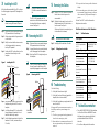
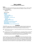
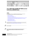
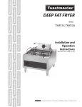
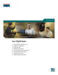
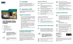
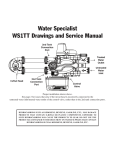
Use an ESD-preventive wrist or ankle
strap during the line card installation.
1 Feature Description
Quick Start Guide
The Cisco uBR10-MC5X20S, U and H cable
interface line cards use 75–ohm precision video
coax cables and 75–ohm MCX connectors to
connect to the CMTS.
This document describes how to install and remove
cables and the second generation universal cable
holder (UCH2).
Figure 1 shows the cards in a Cisco uBR10012
router.
Figure 1
Cisco uBR10-MC5X20S/U/H Cards
MA
INT
uBR10-MC5x20S-D
PO
WE
R
STA
TUS
Upstream
R
STATU
S
MAINT
POWE
R
STATU
S
MAINT
US0
US2
US1
US0
US3
US2
US1
US0
US4
US3
US2
US1
US0
US4
US3
US2
US1
US0
US4
US4
US3
US2
US1
US4
US3
US2
US4
US3
US5
US6
US5
US7
US6
US5
US8
US7
US6
US9
US8
US9
US7
US8
US9
US5
US6
US7
US8
US9
US5
CISCO
10000
US4
US6
US5
US7
US6
US5
US8
US7
US6
US5
US9
US8
US7
US6
US9
US8
US7
US9
US8
The UCH must be used for all Cisco uBR10MC5X20S/U/H line card cable connections.
Failure to use the UCH may cause permanent
damage to the line card connectors and result in
low or no RF output.
US11
US10
US13
US12
US11
CISCO
10000
CISCO
10000
CISCO
10000
Step 1
Loosen the top screws and slide open the
lock bar. (If the UCH2 is already installed
in the line card, use a screwdriver to slide
open the bar. See Figure 5.)
US14
US12
US13
US14
US11
US12
US11
US10
US13
US12
US11
US10
US14
US13
US12
US11
US14
US13
US12
US14
US13
US15
US16
US17
US18
US19
US15
US16
US17
US18
US15
US14
US16
US15
US17
US16
US15
US18
US17
US16
US15
US19
US18
US17
US16
US19
US18
US17
US19
US18
US10
US11
US12
Step 2
Remove the ESD cap from a cable, and
insert it into the hole in the UCH2. See
Figure 2.
US13
US14
US15
SRP
US18
POS
E
SRP
POS
E
ENABL
SRP
POS
E
US17
ENABL
SRP
POS
E
US16
ENABL
US19
ENABL
US19
RX
US19
RX
US18
US10
RX
US17
US10
RX
US16
TX
US13
US15
TX
US14
TX
US10
US12
US19
TX
RX
CD
TX
RX
CD
TX
RX
CD
DS1
DS3
DS2
DS1
DS0
DS3
DS2
DS1
DS0
DS4
DS3
DS2
DS1
DS0
DS4
DS4
DS3
DS2
DS1
DS4
DS3
DS2
DS4
DS3
US14
US16
RF
RF
RF
RF
RF
RF
RF
RF
RF
RF
RF
RF
RF
RF
RF
RF
RF
RF
RF
RF
RF
RF
RF
RF
RF
RF
DS4
RF
US17
US18
US19
72783
DS0RF
DS1RF
DS2RF
DS3RF
DS4RF
RF
OC–48/STM–16 POS/SRP SM–LR
US13
RF
OC–48/STM–16 POS/SRP SM–LR
US12
RF
OC–48/STM–16 POS/SRP SM–LR
US11
RF
OC–48/STM–16 POS/SRP SM–LR
US10
RF
RF
SYNC
DS2
DS4
RF
PASS
THRU
WRAP
DS3
DS0
DS4
SYNC
Downstream
US5
US6
US7
US8
US9
RF
PASS
THRU
WRAP
DS0
RF
SYNC
DS3
DS1
RF
PASS
THRU
WRAP
SYNC
DS0
DS2
RF
PASS
THRU
WRAP
DS1
RF
TX
DS0
DS2
RX
CD
RF
DS1
We recommend that the cables be installed
in the UCH as shown in Table 1 and
Table 2.
DS0RF
DS1RF
DS2RF
DS3RF
DS4RF
1 Feature Description
2 Installing the Cables
3 Installing the UCH
The cables come in kits that consist of cable sets
and spare F connectors.
4 Removing the UCH
The MC5X20 dual-shielded cable kit includes:
5 Removing the Cables
• Two 10-bundle MCX to “F” conn., 3–m cables
6 Troubleshooting
• One 5-bundle MCX to “F” conn., 3–m cables
7 Related Documentation
• 28 spare F connectors
Caution
If using quad-shielded cables, make
sure there is no heat-shrink wrap on
the ends by the MCX connectors.
Table 1
Port—Dual-Shielded Cable Colors
US0–US9
US0 to US9–red, white, blue, green,
yellow, violet, orange, black, gray,
brown, respectively.
US10–US19
US10–grey; US11–brown; US12 to
US19–red, white, blue, green, yellow,
violet, orange, black, respectively.
The MC5X20 quad-shielded cable kit includes:
Warning
Only trained and qualified
personnel should be allowed to
install, replace, or service this
equipment.
US0 to US9–red, white, blue, green,
yellow, red, white, blue, green, yellow,
respectively.
US10–US19
US10 to US19–red, white, blue, green,
yellow, red, white, blue, green, yellow,
respectively.
DS0–DS4
DS0 to DS4–red, white, blue, green,
yellow, respectively.
2 Installing the Cables
TX
US11
US0–US9
Step 3
US9
US10
DS0
US15
Cabling the
Cisco uBR10-MC5X20S/U/H
Cable Interface Line Card with
Universal Cable Holder—UCH2
POWE
US1
US3
Tools required for cable installation include:
• 1/4-in. slotted screwdriver and T-10 TORX
driver
Also see “Tool Manufacturers and Part Numbers.”
FAIL
US9
R
STATU
S
MAINT
US0
US2
US4
FAIL
US8
POWE
US1
US3
FAIL
US7
R
STATU
S
MAINT
US0
US2
FAIL
US6
POWE
US0
US1
In European markets only, you must use
the quad-shielded cable kit with the
Cisco uBR10-MC5X20H.
Port—Quad-Shielded Cable Colors
Insert the cable completely into the UCH.
(The cables will fit loosely in the holes
until the lock bar is closed in Step 5.)
Caution
Do not kink the cables.
Figure 2
Inserting a Cable in the UCH2
uBR10-MC5x20S-D
Is Cisco documentation helpful? Click here or go to
http://forums.cisco.com/eforum/servlet/viewsflash?cmd=s
howform&pollid=rtgdoc01!rtgdoc to give us your
feedback.
US5
R
STATU
S
MAINT
uBR10-MC5x20S-D
US4
POWE
uBR10-MC5x20S-D
US3
R
STATU
S
MAINT
uBR10-MC5x20S-D
US2
POWE
uBR10-MC5x20S-D
US1
R
STATU
S
MAINT
uBR10-MC5x20S-D
US0
POWE
uBR10-MC5x20S-D
R
STATU
S
MAINT
uBR10-MC5x20S-D
POWE
US0
US1
US2
US3
US4
Note
Table 2
• Five 5-bundle MCX to “F” conn., 3–m cables
• Five spare F connectors
The cable kits do not contain the universal cable
holder (UCH); however, the UCH is available with
DS0–DS4
DS0 to DS4–red, white, blue, green,
yellow, respectively.
155826
Caution
line card accessory kits and spare cards. Or, the
UCH2 is available as a spare.
Step 4
Repeat this procedure for all of the cables.
Step 5
Ensure the cables are fully inserted in the
UCH2 and slide the lock bar closed
completely. (The lock bar will not close if
cables are not fully inserted or properly
aligned.)
Step 6
Using the T-10 TORX driver tool tighten
the screws on the lock bar (maximum
torque—10 in-lbs).
Corporate Headquarters
Cisco Systems, Inc.
170 West Tasman Drive
San Jose, CA 95134-1706
USA
http://www.cisco.com
Tel: 408 526-4000
800 553-NETS (6387)
Fax: 408 526-4100
Copyright © 2006 Cisco Systems, Inc. All rights reserved. Cisco, Cisco IOS, Cisco Systems, and
the Cisco Systems logo are registered trademarks of Cisco Systems, Inc. or its affiliates in the U.S.
and certain other countries. All other trademarks mentioned in this document or Website are the
property of their respective owners. The use of the word partner does not imply a partnership
relationship between Cisco and any other company. (0601R)
Printed in the USA on recycled paper containing 10% postconsumer waste.
78-17657-02
3 Installing the UCH
After the cables are installed in the UCH, perform
the following steps to prevent ESD damage to the
line card.
Caution
The UCH is fully engaged when the
semi-circles on the shroud show metal and
the red and black lines are completely
covered. See Figure 3.
Before proceeding, remove the protective
sticker covering the line card DS ports.
Make sure that you are grounded using an
ESD-preventive wrist or ankle strap.
Step 1
Attach a jumper cable to the ground point
on the chassis.
Step 2
Step 3
Briefly touch each cable’s center connector
with the jumper cable to remove any
built-up ESD potential.
Step 4
Position the UCH2 so the red line is on the
same side as the red triangle on the
faceplate.
Figure 3
3. Keep test cables as short as possible to limit static
buildup.
Use the T-10 TORX driver tool to loosen
the lock bar on the side you want to
remove cables.
Step 2
Slide the lock bar open by hand, or with a
flathead screwdriver if the bar is stuck or
hard to access. See Figure 5.
Contact Cisco TAC for further information:
(Make sure the lock bar is completely open
or the cables will not release.)
Tool Manufacturers and Part Numbers
Caution
Step 1
Make sure that you are grounded using an
ESD-preventive wrist or ankle strap.
Step 2
Loosen the lead screw (counterclockwise)
until it disengages from the faceplate.
Step 3
Gently pull the UCH straight away from
the faceplate.
Note
Small pin
US0
US1
Red triangle
Figure 4
Step 3
Figure 5
Be careful not to bend the cables.
Carefully pull the cable out of the hole.
Sliding Open the Lock Bar
Removing the UCH
US3
US4
Red line
Shroud
US1
US9
US2
Step 5
Step 6
Step 7
Shroud
US3
Large pin
Hold the cables and UCH in place while
finger tightening the leadscrew. Do not
bend the cables at right angles.
Use the flathead screwdriver to tighten the
leadscrew 10 in–lbs, (maximum torque
15 in.-lbs).
2. Verify that the shroud fits snugly against the
faceplate (the cutouts are closed).
US5
US6
US7
3. Verify that the cables are properly seated and
secure in the UCH.
US8
Align the end pins with the pin holes in the
faceplate, and guide the UCH onto the
faceplate.
US9
1/4 in. flathead
screwdriver
Check the following:
1. Verify that the lead screw is tight.
US4
155818
Cutout
Lead screw
6 Troubleshooting
US0
US8
155819
US7
Cisco Systems
MC5X20 dual-shielded
MC5X20 quad-shielded
UCH2
CAB-RFSW520TPMF=
CAB-RFSW520QTPMF=
CAB-520-UCH2
F and MCX crimper tool
PN–ACT-483
MCX connector strip tool:
Dual-shielded cables
Quad-shielded cables
PN–CPT-7538-125
PN–CPT-7538-200Q
Dual-shielded F connector
strip tool
US2
US6
Tool Part Numbers
White Sands Engineering, Inc.
If the UCH does not easily pull away from
the card, loosen the lead screw until it
completely disengages from the faceplate.
US5
http://www.cisco.com/tac
Table 3
4 Removing the UCH
Installing the UCH
Red line
4. Before attaching any test cables to the unit under
test, momentarily ground the center pin of the test
cable to remove any ESD potential that may be
present.
Step 1
155820
Note
Torquing the leadscrew to more than
20 in-lbs can cause the leadscrew to
fail.
5 Removing the Cables
If downstream RF power measurements are made, use
these ESD precautions to prevent damage to the
product:
1. Check for a proper ground on the equipment and
chassis before connecting any cables.
2. Ensure that there is a common ground between all
the test equipment that you are using and the unit
under test.
CPT-7538
Quad-shielded F connector CPT-7538Q
strip tool
75–ohm precision miniature
video cable:
Dual-shielded single cable PN–WS940
Quad-shielded five pk
PN–WS386
MCX fixed pin conn.:
Dual-shielded cable
Quad-shielded cable
PN–MCXFP
PN–MCXFPQ
F conn.:
Dual-shielded cable
Quad-shielded cable
PN–ASFP
PN–ASFPQ
7 Related Documentation
• Cisco uBR10-MC5X20S/U/H Cable Interface
Line Card for the Cisco uBR10012 Router:
http://www.cisco.com/univercd/cc/td/doc/
product/cable/ubr10k/ubr10012/frus/
index.htm
• More Cisco cable products information:
http://www.cisco.com/warp/public/44/jump/
cable.shtml