1
Cisco SFS 7000P Hardware
Installation Guide
May 2006
Corporate Headquarters
Cisco Systems, Inc.
170 West Tasman Drive
San Jose, CA 95134-1706
USA
http://www.cisco.com
Tel: 408 526-4000
800 553-NETS (6387)
Fax: 408 526-4100
Customer Order Number:
Text Part Number: OL-9167-01 Rev. A0
THE SPECIFICATIONS AND INFORMATION REGARDING THE PRODUCTS IN THIS MANUAL ARE SUBJECT TO CHANGE WITHOUT
NOTICE. ALL STATEMENTS, INFORMATION, AND RECOMMENDATIONS IN THIS MANUAL ARE BELIEVED TO BE ACCURATE BUT
ARE PRESENTED WITHOUT WARRANTY OF ANY KIND, EXPRESS OR IMPLIED. USERS MUST TAKE FULL RESPONSIBILITY FOR
THEIR APPLICATION OF ANY PRODUCTS.
THE SOFTWARE LICENSE AND LIMITED WARRANTY FOR THE ACCOMPANYING PRODUCT ARE SET FORTH IN THE INFORMATION
PACKET THAT SHIPPED WITH THE PRODUCT AND ARE INCORPORATED HEREIN BY THIS REFERENCE. IF YOU ARE UNABLE TO
LOCATE THE SOFTWARE LICENSE OR LIMITED WARRANTY, CONTACT YOUR CISCO REPRESENTATIVE FOR A COPY.
The following information is for FCC compliance of Class A devices: This equipment has been tested and found to comply with the limits for a Class
A digital device, pursuant to part 15 of the FCC rules. These limits are designed to provide reasonable protection against harmful interference when
the equipment is operated in a commercial environment. This equipment generates, uses, and can radiate radio-frequency energy and, if not installed
and used in accordance with the instruction manual, may cause harmful interference to radio communications. Operation of this equipment in a
residential area is likely to cause harmful interference, in which case users will be required to correct the interference at their own expense.
The following information is for FCC compliance of Class B devices: The equipment described in this manual generates and may radiate
radio-frequency energy. If it is not installed in accordance with Cisco’s installation instructions, it may cause interference with radio and television
reception. This equipment has been tested and found to comply with the limits for a Class B digital device in accordance with the specifications in
part 15 of the FCC rules. These specifications are designed to provide reasonable protection against such interference in a residential installation.
However, there is no guarantee that interference will not occur in a particular installation.
Modifying the equipment without Cisco’s written authorization may result in the equipment no longer complying with FCC requirements for Class
A or Class B digital devices. In that event, your right to use the equipment may be limited by FCC regulations, and you may be required to correct
any interference to radio or television communications at your own expense.
You can determine whether your equipment is causing interference by turning it off. If the interference stops, it was probably caused by the Cisco
equipment or one of its peripheral devices. If the equipment causes interference to radio or television reception, try to correct the interference by
using one or more of the following measures:
• Turn the television or radio antenna until the interference stops.
• Move the equipment to one side or the other of the television or radio.
• Move the equipment farther away from the television or radio.
• Plug the equipment into an outlet that is on a different circuit from the television or radio. (That is, make certain the equipment and the television
or radio are on circuits controlled by different circuit breakers or fuses.)
Modifications to this product not authorized by Cisco Systems, Inc. could void the FCC approval and negate your authority to operate the product.
The Cisco implementation of TCP header compression is an adaptation of a program developed by the University of California, Berkeley (UCB) as
part of UCB’s public domain version of the UNIX operating system. All rights reserved. Copyright © 1981, Regents of the University of California.
NOTWITHSTANDING ANY OTHER WARRANTY HEREIN, ALL DOCUMENT FILES AND SOFTWARE OF THESE SUPPLIERS ARE
PROVIDED “AS IS” WITH ALL FAULTS. CISCO AND THE ABOVE-NAMED SUPPLIERS DISCLAIM ALL WARRANTIES, EXPRESSED
OR IMPLIED, INCLUDING, WITHOUT LIMITATION, THOSE OF MERCHANTABILITY, FITNESS FOR A PARTICULAR PURPOSE AND
NONINFRINGEMENT OR ARISING FROM A COURSE OF DEALING, USAGE, OR TRADE PRACTICE.
IN NO EVENT SHALL CISCO OR ITS SUPPLIERS BE LIABLE FOR ANY INDIRECT, SPECIAL, CONSEQUENTIAL, OR INCIDENTAL
DAMAGES, INCLUDING, WITHOUT LIMITATION, LOST PROFITS OR LOSS OR DAMAGE TO DATA ARISING OUT OF THE USE OR
INABILITY TO USE THIS MANUAL, EVEN IF CISCO OR ITS SUPPLIERS HAVE BEEN ADVISED OF THE POSSIBILITY OF SUCH
DAMAGES.
CCSP, CCVP, the Cisco Square Bridge logo, Follow Me Browsing, and StackWise are trademarks of Cisco Systems, Inc.; Changing the Way We
Work, Live, Play, and Learn, and iQuick Study are service marks of Cisco Systems, Inc.; and Access Registrar, Aironet, BPX, Catalyst, CCDA,
CCDP, CCIE, CCIP, CCNA, CCNP, Cisco, the Cisco Certified Internetwork Expert logo, Cisco IOS, Cisco Press, Cisco Systems, Cisco Systems
Capital, the Cisco Systems logo, Cisco Unity, Enterprise/Solver, EtherChannel, EtherFast, EtherSwitch, Fast Step, FormShare, GigaDrive,
GigaStack, HomeLink, Internet Quotient, IOS, IP/TV, iQ Expertise, the iQ logo, iQ Net Readiness Scorecard, LightStream, Linksys, MeetingPlace,
MGX, the Networkers logo, Networking Academy, Network Registrar, Packet, PIX, Post-Routing, Pre-Routing, ProConnect, RateMUX,
ScriptShare, SlideCast, SMARTnet, The Fastest Way to Increase Your Internet Quotient, and TransPath are registered trademarks of Cisco Systems,
Inc. and/or its affiliates in the United States and certain other countries.
All other trademarks mentioned in this document or Website are the property of their respective owners. The use of the word partner does not imply
a partnership relationship between Cisco and any other company. (0601R)
Cisco SFS 7000P Hardware Installation Guide
© 2006 Cisco Systems, Inc. All rights reserved.
CONTENTS
Audience ix
Organization x
Conventions x
Statement 1071—Warning Definition xii
Related Documentation xvi
Obtaining Documentation xvii
Cisco.com xvii
Product Documentation DVD xvii
Ordering Documentation xviii
Documentation Feedback xviii
Cisco Product Security Overview xviii
Reporting Security Problems in Cisco Products xix
Obtaining Technical Assistance xx
Cisco Technical Support & Documentation Website xx
Submitting a Service Request xxi
Definitions of Service Request Severity xxi
Obtaining Additional Publications and Information xxii
CHAPTER
1
Product Overview 1-1
Switch Description 1-1
Connectors 1-2
Switch Components 1-2
LEDs 1-2
Power Supplies and Fan Units 1-2
Cisco SFS 7000P Hardware Installation Guide
OL-9167-01 Rev. A0
v
Contents
Power Supply Bay 1-2
Power Supplies and Fan Trays 1-3
System Features 1-3
InfiniBand Connectivity 1-3
Scalability 1-3
High Availability 1-3
Hardware 1-4
Ports 1-4
Fabric 1-4
Nonblocking Architecture 1-5
Administrative Features 1-5
Real-Time Clock 1-5
Latency 1-5
Nonvolatile Memory 1-5
Vital Product Data Storage 1-5
Diagnostics 1-6
CHAPTER
2
Installing the Cisco SFS 7000P Switch 2-1
Safety 2-2
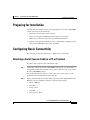
Preparing for Installation 2-3
Configuring Basic Connectivity 2-3
Attaching a Serial Console Cable to a PC or Terminal 2-3
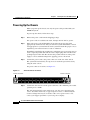
Powering Up the Chassis 2-4
Rack-Mounting the Cisco SFS 7000P Switch 2-5
Requirements 2-5
Rack-Mounting the Switch 2-6
Installing the Switch with One Person 2-6
Installing the Switch with Two People 2-11
Connecting Network Devices 2-11
Cisco SFS 7000P Hardware Installation Guide
vi
OL-9167-01 Rev. A0
Contents
Connecting InfiniBand Devices 2-12
Connecting Management Devices 2-15
Managing the System 2-15
CHAPTER
3
Installing Field Replaceable Units 3-1
Power and Fan Modules 3-1
Locating the Power Supply or Fan Unit 3-1
Failed Power Supplies or Fan Units 3-2
Installing a Power Supply or Fan Unit 3-2
Removing Power Supplies and Fan Units 3-5
CHAPTER
4
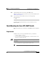
Managing the Cisco SFS 7000P Switch 4-1
LEDs 4-1
Chassis Status LEDs 4-1
InfiniBand Port LEDs 4-2
Power Supply and Fan LEDs 4-3
Managing the System with Element Manager 4-3
Using the Summary Tab 4-4
Using the Power Supplies Tab 4-5
Using the Fans Tab 4-5
Using the Sensors Tab 4-6
Displaying System Information 4-6
Displaying Power Supply Information 4-7
Displaying Fan Information 4-7
Displaying Sensor Information 4-8
CHAPTER
5
Hardware Diagnostic Tests 5-1
About Diagnostic Tests 5-1
LED Tests 5-1
Cisco SFS 7000P Hardware Installation Guide
OL-9167-01 Rev. A0
vii
Contents
Self-Tests 5-2
Running Card Tests 5-2
Running a Card Self-Test 5-2
Running Chassis Tests 5-3
Running a Chassis Standard Test 5-3
Running Fan Tests 5-5
Running a Self-Test on a Fan 5-5
Running Power Supply Tests 5-7
Running a LED Test on the Power Supply 5-7
Running a Self-Test on a Power Supply 5-7
Displaying Hardware Errors 5-9
APPENDIX
A
Specifications and Compliance Certifications A-1
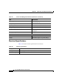
Chassis and Management Interface A-1
Electrical Specifications A-2
INDEX
Cisco SFS 7000P Hardware Installation Guide
viii
OL-9167-01 Rev. A0
Preface
This preface describes who should read the Cisco SFS 7000P Hardware
Installation Guide, how it is organized, and its document conventions.
Audience
Only trained and qualified service personnel (as defined in IEC 60950 and
AS/NZS3260) should install, replace, or service the equipment described in this
publication.
Cisco SFS 7000P Hardware Installation Guide
OL-9167-01 Rev. A0
ix
Preface
Organization
Organization
This publication is organized as follows:
Chapter
Title
Description
Chapter 1
Product Overview
Provides an overview of the Cisco SFS 7000P switch
features.
Chapter 2
Installing the Cisco SFS
7000P Switch
Describes how to install the switch in a rack.
Chapter 3
Installing Field
Replaceable Units
Describes how to install and remove field-replaceable
units (FRUs) on the switch.
Chapter 4
Managing the Cisco SFS Provides upgrade procedures for switch components.
7000P Switch
Chapter 5
Hardware Diagnostic
Tests
Describes how to monitor switch performance.
Appendix A
Specifications and
Compliance
Certifications
Provides specifications and compliance information.
Conventions
This publication uses the following conventions:
Convention
Description
boldface font
Commands, command options, and keywords are in boldface.
italic font
Arguments for which you supply values are in italics.
[ ]
Elements in square brackets are optional.
{x|y|z}
Alternative keywords are grouped in braces and separated by vertical bars.
[x|y|z]
Optional alternative keywords are grouped in brackets and separated by
vertical bars.
string
A nonquoted set of characters. Do not use quotation marks around the string
or the string will include the quotation marks.
Cisco SFS 7000P Hardware Installation Guide
x
OL-9167-01 Rev. A0
Preface
Conventions
Convention
screen
Description
font
Terminal sessions and information the system displays are in screen font.
boldface screen
font
Information you must enter is in boldface screen font.
italic screen font
Arguments for which you supply values are in italic screen font.
^
The symbol ^ represents the key labeled Control. For example, the key
combination ^D in a screen display means hold down the Control key while
you press the D key.
< >
Nonprinting characters, such as passwords, are in angle brackets.
Notes use the following conventions:
Note
Means reader take note. Notes contain helpful suggestions or references to
material not covered in the publication.
Cautions use the following conventions:
Caution
Means reader be careful. In this situation, you might do something that could
result in equipment damage or loss of data.
Cisco SFS 7000P Hardware Installation Guide
OL-9167-01 Rev. A0
xi
Preface
Conventions
Warnings use the following conventions:
Statement 1071—Warning Definition
Warning
IMPORTANT SAFETY INSTRUCTIONS
This warning symbol means danger. You are in a situation that could cause
bodily injury. Before you work on any equipment, be aware of the hazards
involved with electrical circuitry and be familiar with standard practices for
preventing accidents. Use the statement number provided at the end of each
warning to locate its translation in the translated safety warnings that
accompanied this device.
SAVE THESE INSTRUCTIONS
Waarschuwing
BELANGRIJKE VEILIGHEIDSINSTRUCTIES
Dit waarschuwingssymbool betekent gevaar. U verkeert in een situatie die
lichamelijk letsel kan veroorzaken. Voordat u aan enige apparatuur gaat
werken, dient u zich bewust te zijn van de bij elektrische schakelingen
betrokken risico's en dient u op de hoogte te zijn van de standaard praktijken
om ongelukken te voorkomen. Gebruik het nummer van de verklaring
onderaan de waarschuwing als u een vertaling van de waarschuwing die bij
het apparaat wordt geleverd, wilt raadplegen.
BEWAAR DEZE INSTRUCTIES
Varoitus
TÄRKEITÄ TURVALLISUUSOHJEITA
Tämä varoitusmerkki merkitsee vaaraa. Tilanne voi aiheuttaa ruumiillisia
vammoja. Ennen kuin käsittelet laitteistoa, huomioi sähköpiirien
käsittelemiseen liittyvät riskit ja tutustu onnettomuuksien yleisiin
ehkäisytapoihin. Turvallisuusvaroitusten käännökset löytyvät laitteen
mukana toimitettujen käännettyjen turvallisuusvaroitusten joukosta
varoitusten lopussa näkyvien lausuntonumeroiden avulla.
SÄILYTÄ NÄMÄ OHJEET
Cisco SFS 7000P Hardware Installation Guide
xii
OL-9167-01 Rev. A0
Preface
Conventions
Attention
IMPORTANTES INFORMATIONS DE SÉCURITÉ
Ce symbole d'avertissement indique un danger. Vous vous trouvez dans une
situation pouvant entraîner des blessures ou des dommages corporels. Avant
de travailler sur un équipement, soyez conscient des dangers liés aux circuits
électriques et familiarisez-vous avec les procédures couramment utilisées
pour éviter les accidents. Pour prendre connaissance des traductions des
avertissements figurant dans les consignes de sécurité traduites qui
accompagnent cet appareil, référez-vous au numéro de l'instruction situé à la
fin de chaque avertissement.
CONSERVEZ CES INFORMATIONS
Warnung
WICHTIGE SICHERHEITSHINWEISE
Dieses Warnsymbol bedeutet Gefahr. Sie befinden sich in einer Situation, die
zu Verletzungen führen kann. Machen Sie sich vor der Arbeit mit Geräten mit
den Gefahren elektrischer Schaltungen und den üblichen Verfahren zur
Vorbeugung vor Unfällen vertraut. Suchen Sie mit der am Ende jeder Warnung
angegebenen Anweisungsnummer nach der jeweiligen Übersetzung in den
übersetzten Sicherheitshinweisen, die zusammen mit diesem Gerät
ausgeliefert wurden.
BEWAHREN SIE DIESE HINWEISE GUT AUF.
Avvertenza
IMPORTANTI ISTRUZIONI SULLA SICUREZZA
Questo simbolo di avvertenza indica un pericolo. La situazione potrebbe
causare infortuni alle persone. Prima di intervenire su qualsiasi
apparecchiatura, occorre essere al corrente dei pericoli relativi ai circuiti
elettrici e conoscere le procedure standard per la prevenzione di incidenti.
Utilizzare il numero di istruzione presente alla fine di ciascuna avvertenza per
individuare le traduzioni delle avvertenze riportate in questo documento.
CONSERVARE QUESTE ISTRUZIONI
Cisco SFS 7000P Hardware Installation Guide
OL-9167-01 Rev. A0
xiii
Preface
Conventions
Advarsel
VIKTIGE SIKKERHETSINSTRUKSJONER
Dette advarselssymbolet betyr fare. Du er i en situasjon som kan føre til skade
på person. Før du begynner å arbeide med noe av utstyret, må du være
oppmerksom på farene forbundet med elektriske kretser, og kjenne til
standardprosedyrer for å forhindre ulykker. Bruk nummeret i slutten av hver
advarsel for å finne oversettelsen i de oversatte sikkerhetsadvarslene som
fulgte med denne enheten.
TA VARE PÅ DISSE INSTRUKSJONENE
Aviso
INSTRUÇÕES IMPORTANTES DE SEGURANÇA
Este símbolo de aviso significa perigo. Você está em uma situação que poderá
ser causadora de lesões corporais. Antes de iniciar a utilização de qualquer
equipamento, tenha conhecimento dos perigos envolvidos no manuseio de
circuitos elétricos e familiarize-se com as práticas habituais de prevenção de
acidentes. Utilize o número da instrução fornecido ao final de cada aviso para
localizar sua tradução nos avisos de segurança traduzidos que acompanham
este dispositivo.
GUARDE ESTAS INSTRUÇÕES
¡Advertencia!
INSTRUCCIONES IMPORTANTES DE SEGURIDAD
Este símbolo de aviso indica peligro. Existe riesgo para su integridad física.
Antes de manipular cualquier equipo, considere los riesgos de la corriente
eléctrica y familiarícese con los procedimientos estándar de prevención de
accidentes. Al final de cada advertencia encontrará el número que le ayudará
a encontrar el texto traducido en el apartado de traducciones que acompaña
a este dispositivo.
GUARDE ESTAS INSTRUCCIONES
Cisco SFS 7000P Hardware Installation Guide
xiv
OL-9167-01 Rev. A0
Preface
Conventions
Varning!
VIKTIGA SÄKERHETSANVISNINGAR
Denna varningssignal signalerar fara. Du befinner dig i en situation som kan
leda till personskada. Innan du utför arbete på någon utrustning måste du vara
medveten om farorna med elkretsar och känna till vanliga förfaranden för att
förebygga olyckor. Använd det nummer som finns i slutet av varje varning för
att hitta dess översättning i de översatta säkerhetsvarningar som medföljer
denna anordning.
SPARA DESSA ANVISNINGAR
Cisco SFS 7000P Hardware Installation Guide
OL-9167-01 Rev. A0
xv
Preface
Related Documentation
Related Documentation
For instructions on installing and configuring Cisco SFS 7000P and 7008P
switches, refer to these publications:
•
Cisco SFS 7008P Hardware Installation Guide
•
Cisco SFS 7000P Switch Installation and Configuration Note
•
Cisco SFS 7008P Switch Installation and Configuration Note
•
Cisco SFS 7000 Series Product Family Chassis Manager User Guide
•
Cisco SFS 7000 Series Product Family Element Manager User Guide
•
Regulatory Compliance and Safety Information for the Cisco SFS 7000 Series
Switches
Cisco SFS 7000P Hardware Installation Guide
xvi
OL-9167-01 Rev. A0
Preface
Obtaining Documentation
Obtaining Documentation
Cisco documentation and additional literature are available on Cisco.com. Cisco
also provides several ways to obtain technical assistance and other technical
resources. These sections explain how to obtain technical information from Cisco
Systems.
Cisco.com
You can access the most current Cisco documentation at this URL:
http://www.cisco.com/techsupport
You can access the Cisco website at this URL:
http://www.cisco.com
You can access international Cisco websites at this URL:
http://www.cisco.com/public/countries_languages.shtml
Product Documentation DVD
The Product Documentation DVD is a comprehensive library of technical product
documentation on a portable medium. The DVD enables you to access multiple
versions of installation, configuration, and command guides for Cisco hardware
and software products. With the DVD, you have access to the same HTML
documentation that is found on the Cisco website without being connected to the
Internet. Certain products also have .PDF versions of the documentation
available.
The Product Documentation DVD is available as a single unit or as a subscription.
Registered Cisco.com users (Cisco direct customers) can order a Product
Documentation DVD (product number DOC-DOCDVD= or
DOC-DOCDVD=SUB) from Cisco Marketplace at this URL:
http://www.cisco.com/go/marketplace/
Cisco SFS 7000P Hardware Installation Guide
OL-9167-01 Rev. A0
xvii
Preface
Documentation Feedback
Ordering Documentation
Registered Cisco.com users may order Cisco documentation at the Product
Documentation Store in the Cisco Marketplace at this URL:
http://www.cisco.com/go/marketplace/
Nonregistered Cisco.com users can order technical documentation from 8:00 a.m.
to 5:00 p.m. (0800 to 1700) PDT by calling 1 866 463-3487 in the United States
and Canada, or elsewhere by calling 011 408 519-5055. You can also order
documentation by e-mail at [email protected] or by fax at
1 408 519-5001 in the United States and Canada, or elsewhere at 011 408
519-5001.
Documentation Feedback
You can rate and provide feedback about Cisco technical documents by
completing the online feedback form that appears with the technical documents
on Cisco.com.
You can submit comments about Cisco documentation by using the response card
(if present) behind the front cover of your document or by writing to the following
address:
Cisco Systems
Attn: Customer Document Ordering
170 West Tasman Drive
San Jose, CA 95134-9883
We appreciate your comments.
Cisco Product Security Overview
Cisco provides a free online Security Vulnerability Policy portal at this URL:
http://www.cisco.com/en/US/products/products_security_vulnerability_policy.ht
ml
Cisco SFS 7000P Hardware Installation Guide
xviii
OL-9167-01 Rev. A0
Preface
Cisco Product Security Overview
From this site, you will find information about how to:
•
Report security vulnerabilities in Cisco products.
•
Obtain assistance with security incidents that involve Cisco products.
•
Register to receive security information from Cisco.
A current list of security advisories, security notices, and security responses for
Cisco products is available at this URL:
http://www.cisco.com/go/psirt
To see security advisories, security notices, and security responses as they are
updated in real time, you can subscribe to the Product Security Incident Response
Team Really Simple Syndication (PSIRT RSS) feed. Information about how to
subscribe to the PSIRT RSS feed is found at this URL:
http://www.cisco.com/en/US/products/products_psirt_rss_feed.html
Reporting Security Problems in Cisco Products
Cisco is committed to delivering secure products. We test our products internally
before we release them, and we strive to correct all vulnerabilities quickly. If you
think that you have identified a vulnerability in a Cisco product, contact PSIRT:
•
For Emergencies only — [email protected]
An emergency is either a condition in which a system is under active attack
or a condition for which a severe and urgent security vulnerability should be
reported. All other conditions are considered nonemergencies.
•
For Nonemergencies — [email protected]
In an emergency, you can also reach PSIRT by telephone:
Tip
•
1 877 228-7302
•
1 408 525-6532
We encourage you to use Pretty Good Privacy (PGP) or a compatible product (for
example, GnuPG) to encrypt any sensitive information that you send to Cisco.
PSIRT can work with information that has been encrypted with PGP versions 2.x
through 9.x.
Never use a revoked or an expired encryption key. The correct public key to use
Cisco SFS 7000P Hardware Installation Guide
OL-9167-01 Rev. A0
xix
Preface
Obtaining Technical Assistance
in your correspondence with PSIRT is the one linked in the Contact Summary
section of the Security Vulnerability Policy page at this URL:
http://www.cisco.com/en/US/products/products_security_vulnerability_policy.ht
ml
The link on this page has the current PGP key ID in use.
If you do not have or use PGP, contact PSIRT at the aforementioned e-mail
addresses or phone numbers before sending any sensitive material to find other
means of encrypting the data.
Obtaining Technical Assistance
Cisco Technical Support provides 24-hour-a-day award-winning technical
assistance. The Cisco Technical Support & Documentation website on Cisco.com
features extensive online support resources. In addition, if you have a valid Cisco
service contract, Cisco Technical Assistance Center (TAC) engineers provide
telephone support. If you do not have a valid Cisco service contract, contact your
reseller.
Cisco Technical Support & Documentation Website
The Cisco Technical Support & Documentation website provides online
documents and tools for troubleshooting and resolving technical issues with Cisco
products and technologies. The website is available 24 hours a day, at this URL:
http://www.cisco.com/techsupport
Access to all tools on the Cisco Technical Support & Documentation website
requires a Cisco.com user ID and password. If you have a valid service contract
but do not have a user ID or password, you can register at this URL:
http://tools.cisco.com/RPF/register/register.do
Note
Use the Cisco Product Identification (CPI) tool to locate your product serial
number before submitting a web or phone request for service. You can access the
CPI tool from the Cisco Technical Support & Documentation website by clicking
Cisco SFS 7000P Hardware Installation Guide
xx
OL-9167-01 Rev. A0
Preface
Obtaining Technical Assistance
the Tools & Resources link under Documentation & Tools. Choose Cisco
Product Identification Tool from the Alphabetical Index drop-down list, or click
the Cisco Product Identification Tool link under Alerts & RMAs. The CPI tool
offers three search options: by product ID or model name; by tree view; or for
certain products, by copying and pasting show command output. Search results
show an illustration of your product with the serial number label location
highlighted. Locate the serial number label on your product and record the
information before placing a service call.
Submitting a Service Request
Using the online TAC Service Request Tool is the fastest way to open S3 and S4
service requests. (S3 and S4 service requests are those in which your network is
minimally impaired or for which you require product information.) After you
describe your situation, the TAC Service Request Tool provides recommended
solutions. If your issue is not resolved using the recommended resources, your
service request is assigned to a Cisco engineer. The TAC Service Request Tool is
located at this URL:
http://www.cisco.com/techsupport/servicerequest
For S1 or S2 service requests, or if you do not have Internet access, contact the
Cisco TAC by telephone. (S1 or S2 service requests are those in which your
production network is down or severely degraded.) Cisco engineers are assigned
immediately to S1 and S2 service requests to help keep your business operations
running smoothly.
To open a service request by telephone, use one of the following numbers:
Asia-Pacific: +61 2 8446 7411 (Australia: 1 800 805 227)
EMEA: +32 2 704 55 55
USA: 1 800 553-2447
For a complete list of Cisco TAC contacts, go to this URL:
http://www.cisco.com/techsupport/contacts
Definitions of Service Request Severity
To ensure that all service requests are reported in a standard format, Cisco has
established severity definitions.
Cisco SFS 7000P Hardware Installation Guide
OL-9167-01 Rev. A0
xxi
Preface
Obtaining Additional Publications and Information
Severity 1 (S1)—An existing network is down, or there is a critical impact to your
business operations. You and Cisco will commit all necessary resources around
the clock to resolve the situation.
Severity 2 (S2)—Operation of an existing network is severely degraded, or
significant aspects of your business operations are negatively affected by
inadequate performance of Cisco products. You and Cisco will commit full-time
resources during normal business hours to resolve the situation.
Severity 3 (S3)—Operational performance of the network is impaired, while most
business operations remain functional. You and Cisco will commit resources
during normal business hours to restore service to satisfactory levels.
Severity 4 (S4)—You require information or assistance with Cisco product
capabilities, installation, or configuration. There is little or no effect on your
business operations.
Obtaining Additional Publications and Information
Information about Cisco products, technologies, and network solutions is
available from various online and printed sources.
•
The Cisco Product Quick Reference Guide is a handy, compact reference tool
that includes brief product overviews, key features, sample part numbers, and
abbreviated technical specifications for many Cisco products that are sold
through channel partners. It is updated twice a year and includes the latest
Cisco offerings. To order and find out more about the Cisco Product Quick
Reference Guide, go to this URL:
http://www.cisco.com/go/guide
•
Cisco Marketplace provides a variety of Cisco books, reference guides,
documentation, and logo merchandise. Visit Cisco Marketplace, the company
store, at this URL:
http://www.cisco.com/go/marketplace/
•
Cisco Press publishes a wide range of general networking, training and
certification titles. Both new and experienced users will benefit from these
publications. For current Cisco Press titles and other information, go to Cisco
Press at this URL:
http://www.ciscopress.com
Cisco SFS 7000P Hardware Installation Guide
xxii
OL-9167-01 Rev. A0
Preface
Obtaining Additional Publications and Information
•
Packet magazine is the Cisco Systems technical user magazine for
maximizing Internet and networking investments. Each quarter, Packet
delivers coverage of the latest industry trends, technology breakthroughs, and
Cisco products and solutions, as well as network deployment and
troubleshooting tips, configuration examples, customer case studies,
certification and training information, and links to scores of in-depth online
resources. You can access Packet magazine at this URL:
http://www.cisco.com/packet
•
iQ Magazine is the quarterly publication from Cisco Systems designed to
help growing companies learn how they can use technology to increase
revenue, streamline their business, and expand services. The publication
identifies the challenges facing these companies and the technologies to help
solve them, using real-world case studies and business strategies to help
readers make sound technology investment decisions. You can access iQ
Magazine at this URL:
http://www.cisco.com/go/iqmagazine
or view the digital edition at this URL:
http://ciscoiq.texterity.com/ciscoiq/sample/
•
Internet Protocol Journal is a quarterly journal published by Cisco Systems
for engineering professionals involved in designing, developing, and
operating public and private internets and intranets. You can access the
Internet Protocol Journal at this URL:
http://www.cisco.com/ipj
•
Networking products offered by Cisco Systems, as well as customer support
services, can be obtained at this URL:
http://www.cisco.com/en/US/products/index.html
•
Networking Professionals Connection is an interactive website for
networking professionals to share questions, suggestions, and information
about networking products and technologies with Cisco experts and other
networking professionals. Join a discussion at this URL:
http://www.cisco.com/discuss/networking
•
World-class networking training is available from Cisco. You can view
current offerings at this URL:
http://www.cisco.com/en/US/learning/index.html
Cisco SFS 7000P Hardware Installation Guide
OL-9167-01 Rev. A0
xxiii
Preface
Obtaining Additional Publications and Information
Cisco SFS 7000P Hardware Installation Guide
xxiv
OL-9167-01 Rev. A0
1
C H A P T E R
Product Overview
The Cisco SFS 7000P switch provides data center managers with a
high-performance, low-latency interconnect.
•
Switch Description, page 1-1.
•
System Features, page 1-3.
•
Administrative Features, page 1-5.
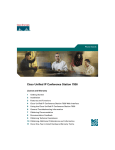
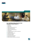
Switch Description
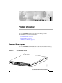
The Cisco SFS 7000P switch includes the features described in the following
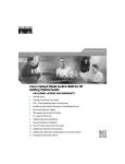
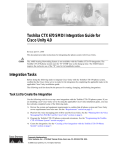
sections. See Figure 1-1 for an illustration of the switch.
Figure 1-1
Cisco SFS 7000P Switch
Power Supply
Power Supply
2
154903
1
Cisco SFS 7000P Hardware Installation Guide
OL-9167-01 Rev. A0
1-1
Chapter 1
Product Overview
Switch Components
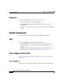
Connectors
The Cisco SFS 7000P switch uses the following connectors:
•
Twenty-four 10-Gbps 4x copper InfiniBand ports
•
One 10/100 Ethernet RJ-45 management-Ethernet port for out-of-band
management
•
One RJ-45 console port used to configure and monitor the Cisco SFS 7000P
switch
Switch Components
The following sections describe the Cisco SFS 7000P switch components.
LEDs
The Cisco SFS 7000P switch features the following LEDs:
•
Chassis LEDs–Show overall system status, power status, and fan status.
LEDs and their use are described in the “Chassis Status LEDs” section on
page 4-1.
•
InfiniBand Port LEDs–Show link status, diagnostics, and network traffic.
LEDs and their use are described in the “LEDs” section on page 4-1.
Power Supplies and Fan Units
See the “Installing a Power Supply or Fan Unit” section on page 3-2 for more
information.
Power Supply Bay
The chassis provides dual independent IEC connectors, left- and right-justified.
Cisco SFS 7000P Hardware Installation Guide
1-2
OL-9167-01 Rev. A0
Chapter 1
Product Overview
System Features
Power Supplies and Fan Trays
The power supplies and fan trays have the following features:
•
Redundant and hot-swappable
The replacement of any one power supply or fan tray does not disrupt the
operation of the device, and can be successfully completed without removing
the device from a rack or disconnecting any cables.
•
Auto-ranging 90 to 264VAC, 47 to 63Hz
•
Redundant, hot-swappable cooling
System Features
This section describes the Cisco SFS 7000P features.
InfiniBand Connectivity
The Cisco SFS 7000P switch can be used in a variety of networking environments,
including database tiers, application tiers, and World Wide Web tiers. The Cisco
SFS 7000P switch provides 10 Gbps connectivity to servers.
InfiniBand-enabled servers are automatically recognized as they are connected.
Scalability
The embedded subnet manager running on the Cisco SFS 7000P switch can
manage up to 1,152 hosts.
High Availability
High availability operates at the hardware, port, and fabric level.
Cisco SFS 7000P Hardware Installation Guide
OL-9167-01 Rev. A0
1-3
Chapter 1
Product Overview
System Features
Hardware
The Cisco SFS 7000P switch features hot-swappable redundant power and
cooling.
Ports
If any single InfiniBand port fails, none of the other ports will have interrupted
service.
Fabric
For redundancy, InfiniBand host channel adapters can be dual-connected to a
redundant pair of Cisco SFS 7000P switches.
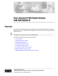
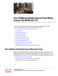
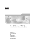
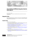
In an InfiniBand fabric that includes more than one Cisco SFS 7000P switch, if
the subnet manager on the Cisco SFS 7000P switch that is acting as the master
fails, another subnet manager will take over within seconds. (See Figure 1-2.)
Example of Redundant Cisco SFS 7000P InfiniBand Fabric
IB Host 1
HCA
HCA
IB Host 2
HCA
HCA
EN mgmt
ports
InfiniBand
Chassis A
Cisco SFS 7000P)
Switch 1
InfiniBand connections
EN mgmt
ports
InfiniBand
Chassis B
(Cisco SFS 7000P)
Switch 1
154001
Figure 1-2
Cisco SFS 7000P Hardware Installation Guide
1-4
OL-9167-01 Rev. A0
Chapter 1
Product Overview
Administrative Features
Nonblocking Architecture
The Cisco SFS 7000P switch provides nonblocking switch element architecture
with full bisectional bandwidth for the switch chassis.
Administrative Features
The following sections describe the Cisco SFS 7000P administrative features.
Real-Time Clock
A real-time clock maintains correct time regardless of power conditions or
connectivity.
Latency
The Cisco SFS 7000P switch has port to port latency of less than 200ns.
Nonvolatile Memory
The memory supports the following items:
•
Three stored system images (not including recovery image)
•
One week of log files at normal verbosity and one day of log files at maximum
verbosity
Vital Product Data Storage
Vital product data is stored in nonvolatile memory in the system and the power
supply and is available electronically. The following vital product data is
accessible by the maintenance processor and made available to the RS-232 and
Ethernet ports:
•
Power-on hours
Cisco SFS 7000P Hardware Installation Guide
OL-9167-01 Rev. A0
1-5
Chapter 1
Product Overview
Administrative Features
•
Manufacturing part number
•
Serial number
•
Final test date
•
Card ID
•
Failure code
•
Failure date
•
Operation status
•
Failure log
•
OEM part number
Diagnostics
The following tests are used to determine operational status:
•
Power-on self-test (POST) is performed on all system components and is
required during power-on to determine operational readiness.
•
Test to check the redundant components’ operational status periodically
during normal operation, including the logic required to perform the
transition from faulted or primary to redundant component. The detection of
an abnormal status is reported.
•
Concurrent port loopback tests are available, including the capability to wrap
an external signal from input port to output port.
Refer to Chapter 5, “Hardware Diagnostic Tests,” for more detailed information.
Cisco SFS 7000P Hardware Installation Guide
1-6
OL-9167-01 Rev. A0
C H A P T E R
2
Installing the Cisco SFS 7000P Switch
This chapter describes how to install and manage the Cisco SFS 7000P switch
hardware.
•
Safety, page 2-2
•
Preparing for Installation, page 2-3
•
Configuring Basic Connectivity, page 2-3
•
Rack-Mounting the Cisco SFS 7000P Switch, page 2-5
•
Connecting Network Devices, page 2-11
•
Managing the System, page 2-15
Warning
Ultimate disposal of this product should be handled according to all national
laws and regulations. Statement 1040
Warning
This equipment must be installed and maintained by service personnel as
defined by AS/NZS 3260. Incorrectly connecting this equipment to a
general-purpose outlet could be hazardous. The telecommunications lines must
be disconnected 1) before unplugging the main power connector or 2) while the
housing is open, or both. Statement 1043
Warning
This product requires short-circuit (overcurrent) protection, to be provided as
part of the building installation. Install only in accordance with national and
local wiring regulations. Statement 1045
Cisco SFS 7000P Hardware Installation Guide
OL-9167-01 Rev. A0
2-1
Chapter 2
Installing the Cisco SFS 7000P Switch
Safety
Warning
During this procedure, wear grounding wrist straps to avoid ESD damage to the
card. Do not directly touch the backplane with your hand or any metal tool, or
you could shock yourself. Statement 93
Safety
Warning
Only trained and qualified personnel should be allowed to install, replace, or
service this equipment. Statement 1030
Warning
This unit is intended for installation in restricted access areas. A restricted
access area can be accessed only through the use of a special tool, lock and
key, or other means of security. Statement 1017
Warning
Before you install, operate, or service the system, read the Site Preparation and
Safety Guide. This guide contains important safety information you should know
before working with the system. Statement 200
Warning
Voltages that present a shock hazard can exist on inline power circuits if
interconnections are made by using uninsulated exposed metal contacts,
conductors, or terminals. Avoid using such interconnection methods unless the
exposed metal parts are in a restricted access location and users and service
people who are authorized to access the location are made aware of the hazard.
A restricted access area can be accessed only through the use of a special tool,
lock and key, or other means of security.
Cisco SFS 7000P Hardware Installation Guide
2-2
OL-9167-01 Rev. A0
Chapter 2
Installing the Cisco SFS 7000P Switch
Preparing for Installation
Preparing for Installation
To safely and successfully prepare your environment for your Cisco SFS 7000P
switch, you need to do the following:
•
Check the contents of the switch package.
•
Always use an approved ESD-preventative ankle or wrist strap.
•
Make sure you have the right cables and sufficient ventilation.
•
Prepare a management workstation, such as a PC running a terminal program,
and a rollover M/F DB-9 serial cable (included).
Configuring Basic Connectivity
The following sections describe how to configure basic connectivity.
Attaching a Serial Console Cable to a PC or Terminal
To attach a serial console cable, follow these steps:
Step 1
Connect the cable from the Cisco SFS 7000P serial console to your terminal or
management workstation using the rollover serial cable. The cable is provided in
the Cisco SFS 7000P package.
For detailed information on how to connect the serial console cable, see the
documentation included with the serial cable kit.
Step 2
Open a terminal emulation window using a program such as HyperTerminal for
Windows. Set your terminal parameters to the following settings:
•
Baud—9600 bps
•
Data Bits—8
•
Parity—None
•
Stop Bits—1
•
Flow control—None
Cisco SFS 7000P Hardware Installation Guide
OL-9167-01 Rev. A0
2-3
Chapter 2
Installing the Cisco SFS 7000P Switch
Configuring Basic Connectivity
Powering Up the Chassis
When you power up the chassis, use only the power cable provided with your
InfiniBand system.
To power up the chassis, follow these steps:
Step 1
Remove the power cords from the shipping package.
Two power cords are available: UL-rated, 10 amps and 125 VAC or greater.
Step 2
Inspect the power cord and determine if it provides the proper plug and is
appropriately certified for use with your electrical system. Discard the cord if it
is inappropriate for your national electrical system and obtain the proper cord, as
required by your national electrical codes or ordinances.
Grounding is supplied by the ground prong on the three-prong power plug. Do not
attach a separate ground cable and do not use adapter plugs. Do not remove the
ground prong from the cable. Be sure that the ground connection on the power
supply is correct and functioning before applying power to the switch.
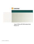
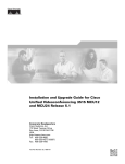
Step 3
Connect the power cords to the power connectors on the rear of the switch.
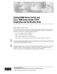
The system will automatically boot up. You can watch the operation status by
using the serial console.
For power connector locations, see Figure 2-1.
Figure 2-1
Power Connector Locations
Power connector
144945
Power connector
Step 4
Connect the other end of each AC power cable into a 90 to 264VAC power outlet
operating at 47 to 63Hz.
The switch automatically starts and boots up. Use the correct external power
source. Attach the switch only to approved power sources, as indicated by the
electrical ratings label. If you are unsure of the correct power-source to use,
contact your support personnel or your local power company.
Cisco SFS 7000P Hardware Installation Guide
2-4
OL-9167-01 Rev. A0
Chapter 2
Installing the Cisco SFS 7000P Switch
Rack-Mounting the Cisco SFS 7000P Switch
Step 5
Check the LEDs on the front of the Cisco SFS 7000P system.
When the system first powers up, it performs a power-on self test (POST). See the
“LEDs” section on page 4-1.
Step 6
Log in and assign a network address after you see the login prompt.
The default login is:
•
super
For additional management information, see the Command Line Interface
Reference Guide.
Rack-Mounting the Cisco SFS 7000P Switch
This section describes how to install the Cisco SFS 7000P switch in an equipment
rack.
Requirements
In addition to the accessories provided with the switch, you should have:
Caution
•
A number 2 Phillips screwdriver
•
12 screws and any associated mounting clips to secure the brackets to your
rack (two for each rail of the rack).
Installing the rack to the system with screws other than the ones provided could
be hazardous.
•
Note
We recommend that two people install the switch in a rack.
The Cisco SFS 7000P switch weighs more than 22 pounds (10 kg).
Cisco SFS 7000P Hardware Installation Guide
OL-9167-01 Rev. A0
2-5
Chapter 2
Installing the Cisco SFS 7000P Switch
Rack-Mounting the Cisco SFS 7000P Switch
Rack-Mounting the Switch
To rack-mount the Cisco SFS 7000P switch in a rack, follow these steps:
Step 1
Remove the switch, rack brackets, CD-ROM, parts bag, and documentation from
the box.
Step 2
Place the switch on a secure, clean surface.
Step 3
Open the plastic bag containing mounting parts.
Step 4
Check the slot in the rack for sufficient clearance.
Step 5
Determine the desired method of installation:
•
Installing the Switch with One Person, page 2-6
•
Installing the Switch with Two People, page 2-11
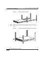
Installing the Switch with One Person
The following method of installation is easier with two people, but can be
accomplished with one person. It can be difficult for only one person to align the
switch correctly along the rack rails.
To install the switch with one person, follow these steps:
Step 1
Separate one set of the rack brackets (see Figure 2-2).
Each side is assembled to its counterpart, but should be separated before attaching
to the switch when you use this method of installation.
Cisco SFS 7000P Hardware Installation Guide
2-6
OL-9167-01 Rev. A0
Chapter 2
Installing the Cisco SFS 7000P Switch
Rack-Mounting the Cisco SFS 7000P Switch
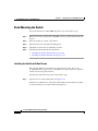
Assembled Rack Brackets
144949
Figure 2-2
Step 2
Attach the bracket that has the screw holes to the side of the switch with the flange
facing away from the switch, as shown in Figure 2-3.
Attaching One Rail to Switch Chassis
144952
Figure 2-3
The standard method is to face the flange toward the front of the switch. However,
you can also mount the flange toward the back if you want to mount the switch
backward in the switch (service-side forward).
Step 3
Repeat steps Step 1 and 2 on the opposite side of the switch.
The two counterparts to these sliding rack brackets (that do not have screw holes)
should still be unattached.
Step 4
Check the rack for clearance for the switch. The switch can be installed either
directly on top of another device, or be suspended from the rack posts.
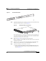
Step 5
Attach the remaining two rack brackets to your rack.
a.
Position a bracket toward the back of the rack with the flange facing away
from the rack. The flange should go around the outside of the rack post, as
shown in Figure 2-4.
Cisco SFS 7000P Hardware Installation Guide
OL-9167-01 Rev. A0
2-7
Chapter 2
Installing the Cisco SFS 7000P Switch
Rack-Mounting the Cisco SFS 7000P Switch
Holding Bracket Against Inside of Rack
144954
Figure 2-4
Note
If you are rack-mounting the switch backward, the bracket should be
installed to the front of the rack.
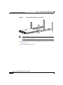
b.
Secure the bracket with your screws through the back of the rack, as shown
in Figure 2-5.
c.
Repeat on both sides of the rack.
Cisco SFS 7000P Hardware Installation Guide
2-8
OL-9167-01 Rev. A0
Chapter 2
Installing the Cisco SFS 7000P Switch
Rack-Mounting the Cisco SFS 7000P Switch
Secure Rail Bracket to Rack with Screws
144953
Figure 2-5
Step 6
Lift the switch unit and align the brackets on the switch with the brackets in the
rack before sliding the brackets together.
Step 7
Carefully push the switch unit into the rack.
If the brackets do not slide easily, the alignment may be off. Pull the switch back
toward you and realign the brackets.
Cisco SFS 7000P Hardware Installation Guide
OL-9167-01 Rev. A0
2-9
Chapter 2
Installing the Cisco SFS 7000P Switch
Rack-Mounting the Cisco SFS 7000P Switch
Sliding the Switch Into the Rack
144954
Figure 2-6
Step 8
Maintain at least six inches between the cooling vents and any obstructions.
Step 9
Secure the switch with your screws through the front of the rack, as shown in
Figure 2-7.
Secure Switch with Screws through the Front of the Rack
144955
Figure 2-7
Cisco SFS 7000P Hardware Installation Guide
2-10
OL-9167-01 Rev. A0
Chapter 2
Installing the Cisco SFS 7000P Switch
Connecting Network Devices
Installing the Switch with Two People
The following method of installation requires two people to mount the switch into
the rack. One person holds the switch while another person secures it to the rack.
To install the switch with two people, follow these steps:
Step 1
Separate the assembled rack brackets (see Figure 2-2).
Step 2
Attach the rack bracket that has screw holes to the sides of the switch with the
screws provided.
When attaching the rack bracket, the flanges of the rack bracket should be facing
away from the switch, as shown in Figure 2-3.
Step 3
Attach the rack brackets to their counterparts before inserting the switch into the
rack.
Step 4
Insert the switch into the rack with the rack bracket attached. You will have to tilt
the switch unit to one side to avoid hitting the sides of the rack bracket with the
brackets as they pass around the back rails.
Return the switch unit to a horizontal position once the switch is inside the rack.
The rear bracket flanges should wrap around the outside of the back rack post.
Step 5
Have one person hold the switch while another person secures the switch to the
rack.
Step 6
Maintain at least six inches between the cooling vents and any obstructions.
Step 7
Attach the rack bracket to the back of the rack posts with screws that fit your rack.
Step 8
Attach the front rails to the front of the rack with screws that fit your rack, as
shown in Figure 2-7.
Connecting Network Devices
This section describes how to connect the InfiniBand system to other network
devices. InfiniBand devices can be connected to InfiniBand-enabled servers.
The Cisco SFS 7000P switch supports the following types of connectors:
•
Serial console port
•
Ethernet Management port—RJ-45 jack for unshielded twisted-pair
connections
Cisco SFS 7000P Hardware Installation Guide
OL-9167-01 Rev. A0
2-11
Chapter 2
Installing the Cisco SFS 7000P Switch
Connecting Network Devices
•
Switch card—4x 10 Gbps InfiniBand connectors
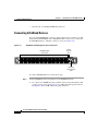
Connecting InfiniBand Devices
If you are using InfiniBand to connect to other workstations or switches, you will
need standard 4x InfiniBand cables. InfiniBand cables can be used to connect any
two InfiniBand devices, whether a switch or a host (see Figure 2-8).
Figure 2-8
InfiniBand and Management Port Connections
Serial
console
port
133860
InfiniBand port
connectors
Ethernet
management
port
To connect InfiniBand devices, follow these steps:
Step 1
Connect InfiniBand cables from the host to the InfiniBand switch.
a.
To connect in an InfiniBand cable, push the connector into the interface until
you hear or feel a click. See Figure 2-9 for an IB cable with a pinch connector.
See Figure 2-10 for an IB cable with a pull connector.
Cisco SFS 7000P Hardware Installation Guide
2-12
OL-9167-01 Rev. A0
Chapter 2
Installing the Cisco SFS 7000P Switch
Connecting Network Devices
Figure 2-9
IB Cable with Pinch Connector
144960
10
Figure 2-10
IB Cable with Pull Connector
144961
13
Cisco SFS 7000P Hardware Installation Guide
OL-9167-01 Rev. A0
2-13
Chapter 2
Installing the Cisco SFS 7000P Switch
Connecting Network Devices
If your host does not provide an ample amount of space around an IB port,
double-check that your IB cable connector engages fully. Move your connector
back and forth to be sure that both sides of the connector have locked firmly into
place.
b.
To remove a cable with a pinch connector, pinch both sides of the back of the
connector and pull the connector away from the port (see Figure 2-11).
Figure 2-11
Removing a Pinch Connector
13
Press here
Press here
c.
144962
Note
To remove a cable with a pull connector, grasp the connector with one hand
and push it toward the port, then pull the latch away from the port with your
other hand and gently move the connector back and forth and away from the
port (see Figure 2-12).
Cisco SFS 7000P Hardware Installation Guide
2-14
OL-9167-01 Rev. A0
Chapter 2
Installing the Cisco SFS 7000P Switch
Managing the System
Figure 2-12
Removing a Pull Connector
Hold here
10
e
144963
Hold here
Connecting Management Devices
To connect the management ports, use either a serial cable or an Ethernet cable.
For the location of the management ports, see Figure 2-8.
Managing the System
You can manage the InfiniBand system using the following methods:
•
Command-Line Interface (CLI) —A text-based interface accessible through
a direct serial connection, Telnet over IP, or SSH over IP.
•
Chassis Manager (GUI)—A web-based graphical user interface.
•
Element Manager (GUI)—A graphical interface installed on a workstation,
accessible over IP.
Cisco SFS 7000P Hardware Installation Guide
OL-9167-01 Rev. A0
2-15
Chapter 2
Installing the Cisco SFS 7000P Switch
Managing the System
See the Cisco SFS 7000 Series Product Family Chassis Manager User Guide, the
Cisco SFS 7000 Series Product Family Element Manager User Guide, and the CLI
Reference Guide for more information about managing InfiniBand systems.
Cisco SFS 7000P Hardware Installation Guide
2-16
OL-9167-01 Rev. A0
Chapter 2
Installing the Cisco SFS 7000P Switch
Managing the System
Cisco SFS 7000P Hardware Installation Guide
OL-9167-01 Rev. A0
2-17
C H A P T E R
3
Installing Field Replaceable Units
This chapter describes how to install the following field replaceable units (FRUs)
in the Cisco SFS 7000P switch:
•
Power and Fan Modules, page 3-1
•
Installing a Power Supply or Fan Unit, page 3-2
•
Removing Power Supplies and Fan Units, page 3-5
Power and Fan Modules
The Cisco SFS 7000P power supplies and fan units are hot-swappable. You can
add a second module without powering off the switch. If you have two power or
fan units installed, you can remove one of them without removing power from the
switch.
Locating the Power Supply or Fan Unit
Each power supply and fan unit is a single module. Both power or fan units are
located on the front of the switch. When facing the front of the switch, the power
modules are located in the left and right slots of the Cisco SFS 7000P switch.
Cisco SFS 7000P Hardware Installation Guide
OL-9167-01 Rev. A0
3-1
Chapter 3
Installing Field Replaceable Units
Installing a Power Supply or Fan Unit
Failed Power Supplies or Fan Units
The status of power supplies and fan units can be checked using the CLI, the
Chassis Manager, or the Element Manager. The available information includes the
status, the vital product data (VPD), the description of the error or an error code.
If you suspect that a power supply module has failed, check the LEDs (see the
“Power Supply and Fan LEDs” section on page 4-3) and view the status through
the Element Manager.
In most cases, vital information can be retrieved from the console port of
management Ethernet port. See the “Vital Product Data Storage” section on
page 1-5.
Refer to the Cisco SFS 7000 Series Product Family Chassis Manager User Guide
or Cisco SFS 7000 Series Product Family Element Manager User Guide for more
information.
Installing a Power Supply or Fan Unit
Caution
Never place your hand inside an empty module bay or anywhere inside the Cisco
SFS 7000P switch.
Caution
Unused module bays should always have a Cisco SFS 7000P filler panel over the
bay to ensure proper safety, ventilation, and cooling.
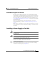
To insert a power supply or fan unit, follow these steps:
Step 1
Ground yourself appropriately.
Step 2
Remove the filler panel from the power supply bay with a number 1 Phillips
screwdriver, if it is still in place (see Figure 3-1).
Cisco SFS 7000P Hardware Installation Guide
OL-9167-01 Rev. A0
3-2
Chapter 3
Installing Field Replaceable Units
Installing a Power Supply or Fan Unit
Removing the Screws from the Power Supply
154010
Figure 3-1
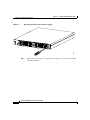
Step 3
Remove the power supply or fan unit if one is in place (or “present”) by pulling
on the black handle.
Cisco SFS 7000P Hardware Installation Guide
3-3
OL-9167-01 Rev. A0
Chapter 3
Installing Field Replaceable Units
Installing a Power Supply or Fan Unit
Removing the Power Supply from the Switch
154011
Figure 3-2
Step 4
Insert the new power supply or fan unit into the open slot until it is fully seated.
You may need to push the unit with your thumbs to get it completely into the bay.
Step 5
Secure fasteners with a number 1 Phillips screwdriver.
Step 6
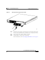
Check the LEDs to verify the status of the module.
For more information, see the “Power Supply and Fan LEDs” section on page 4-3.
Cisco SFS 7000P Hardware Installation Guide
OL-9167-01 Rev. A0
3-4
Chapter 3
Installing Field Replaceable Units
Removing Power Supplies and Fan Units
Power Supply LEDs
154012
Figure 3-3
!
Power Supply
LEDs
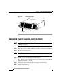
Removing Power Supplies and Fan Units
Caution
Do not remove the power supply or fan unit without first removing the screws. Use
a Phillips screw driver.
Step 1
Make sure you have a number 1 Phillips screwdriver to disengage the fasteners.
Step 2
Ground yourself appropriately.
Caution
Step 3
Never place your hand inside an empty card or module bay or anywhere inside the
Cisco SFS 7000P switch.
Locate the power or fan unit that you want to remove.
If you have two power or fan units installed, you can remove one of them without
removing power from the switch.
Step 4
Unscrew the fasteners that hold the power supply or fan unit in place.
Step 5
Pull the unit from the bay.
Cisco SFS 7000P Hardware Installation Guide
3-5
OL-9167-01 Rev. A0
Chapter 3
Installing Field Replaceable Units
Removing Power Supplies and Fan Units
Step 6
Install the filler panel in place of the power or fan unit.
or
Install a new power supply or fan unit. If you are installing a new power supply
or fan unit, see the “Installing a Power Supply or Fan Unit” section on page 3-2.
Caution
Never operate the device without a filler panel or unit it place because the device
might overheat.
Cisco SFS 7000P Hardware Installation Guide
OL-9167-01 Rev. A0
3-6
Chapter 3
Installing Field Replaceable Units
Removing Power Supplies and Fan Units
Cisco SFS 7000P Hardware Installation Guide
3-7
OL-9167-01 Rev. A0
C H A P T E R
4
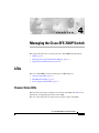
Managing the Cisco SFS 7000P Switch
This chapter describes how to manage the Cisco SFS 7000P switch hardware.
•
LEDs, page 4-1
•
Managing the System with Element Manager, page 4-3
•
Displaying System Information, page 4-6
LEDs
The Cisco SFS 7000P has the following types of LED indicators:
•
Chassis Status LEDs, page 4-1
•
InfiniBand Port LEDs, page 4-2
•
Power Supply and Fan LEDs, page 4-3
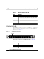
Chassis Status LEDs
The front of the chassis has a single bi-color chassis status LED. See Table 4-1 for
information on interpreting the chassis status LED.
The rear of the chassis has one green and one yellow system status LED.
Cisco SFS 7000P Hardware Installation Guide
OL-9167-01 Rev. A0
4-1
Chapter 4
Managing the Cisco SFS 7000P Switch
LEDs
Table 4-1
Interpreting the Chassis Status LED
Color
Indication
Off
No system power or LED failure.
Yellow (solid)
Operator intervention required. An system error was detected,
such as a fan error, a POST failure, or a power supply failure.
The ! label (available on the back of the chassis) indicates a
failure.
Yellow
(blinking)
Initiated automatically during the LED test that follows the
application of power (16 seconds).
Solid green
Indicates proper operation and no critical errors.
InfiniBand Port LEDs
The InfiniBand port LED is located next to each InfiniBand port. The InfiniBand
LED represents the logical link and the logical link activity. For InfiniBandport
LED locations, see Figure 4-1.
Figure 4-1
InfiniBand Port LEDs Location
154013
Port LEDs
For information on interpreting the InfiniBand Port LED, see Table 4-2.
Table 4-2
InfiniBand Port LED
Color
Indication
Off
Logical link has not been established.
Solid green
Logical link has been established.
Blinking green Logical link was established with activity.
Cisco SFS 7000P Hardware Installation Guide
4-2
OL-9167-01 Rev. A0
Chapter 4
Managing the Cisco SFS 7000P Switch
Managing the System with Element Manager
Power Supply and Fan LEDs
The power supply and fan unit LEDs are located on the bottom left corner of each
power supply or fan unit. For the location of the LEDs, see Figure 4-2. For LED
descriptions, see Table 4-3.
•
The green LED is labeled with a checkmark.
•
The yellow LED is labeled with an exclamation point (!).
Power Supply and Fan LEDs Location
154014
Figure 4-2
!
Power Supply/Fan
LEDs
Table 4-3
Power Supply and Fan Unit LEDs
Color
Indication
Off
DC output failure.
Green (solid)
AC connected, DC output OK.
Yellow (off)
No failure on the power supply.
Yellow (solid)
Operator intervention required. Failure detected
within the power supply.
Managing the System with Element Manager
For information regarding installing the Element Manager, refer to the Cisco SFS
7000 Series Product Family Element Manager User Guide.
Cisco SFS 7000P Hardware Installation Guide
OL-9167-01 Rev. A0
4-3
Chapter 4
Managing the Cisco SFS 7000P Switch
Managing the System with Element Manager
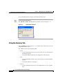
To view the Health Status window, perform the following steps:
Step 1
Launch the Element Manager.
Step 2
Select Health > Status. The Health Status window opens. (See Figure 4-3.)
Figure 4-3
Health Status Window
Using the Summary Tab
Use the Summary tab (See Figure 4-3.) to view the status of the power, fans, and
temperature sensors at once.
The Summary tab has the following fields:
•
Power
– A green check indicates that at least one power source is connected and
functioning properly.
– A red check indicates that the power supply AC is disconnected.
•
Fans
– A green check indicates that at least one fan is present, and is functioning
properly.
– A red check indicates a fan failure.
•
Sensors
– A green check indicates that the system temperature is at an acceptable
level.
Cisco SFS 7000P Hardware Installation Guide
4-4
OL-9167-01 Rev. A0
Chapter 4
Managing the Cisco SFS 7000P Switch
Managing the System with Element Manager
– A red check indicates a high-temperature warning.
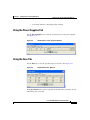
Using the Power Supplies Tab
Use the Power Supplies tab to view the operating status of the power supplies.
(See Figure 4-4.)
Figure 4-4
Health Status Power Supplies Window
Using the Fans Tab
Use the Fans tab to view the operating status of the fans. (See Figure 4-5.)
Figure 4-5
Health Status Fans Window
In the OperStatus field, a status of up indicates that the fan is operating correctly
within the power or fan unit.
Cisco SFS 7000P Hardware Installation Guide
OL-9167-01 Rev. A0
4-5
Chapter 4
Managing the Cisco SFS 7000P Switch
Displaying System Information
In the Speed field, the integer represents a percentage. The percentage changes
based on the ambient temperature of the unit, and will increase as the temperature
rises.
Using the Sensors Tab
Use the Sensors tab to view the operating status of the temperature sensor of the
system. (See Figure 4-6.)
Figure 4-6
Health Status Sensors Window
In the OperStatus field, a status of “up” indicates that the sensor is functioning
properly.
In the Temperature field, the internal system temperature is displayed in Celsius.
The system’s maximum external ambient temperature is 30 degrees Celsius (0 to
10,000 feet). Acceptable internal temperature ranges are 30 degrees Celsius above
external ambient, plus 1 degree for every 1,000 feet above sea level. The system
reboots at an internal temperature of 75 degrees Celsius.
A warning will appear if the temperature reaches 65 degrees Celsius (at sea level).
The system reboots at an internal temperature of 75 degrees Celsius (at sea level).
Displaying System Information
You can use CLI commands to monitor the power supplies, the fans, and the
sensors.
Cisco SFS 7000P Hardware Installation Guide
4-6
OL-9167-01 Rev. A0
Chapter 4
Managing the Cisco SFS 7000P Switch
Displaying System Information
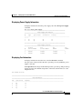
Displaying Power Supply Information
To display information about the power supply, enter the show power-supply
command.
SFS-7000P# show power-supply
===============================================================
Power-supply Information
===============================================================
ps
type
oper-status
utilization
voltage
--------------------------------------------------------------------------1
AC
up
50
12
2
AC
up
50
12
===============================================================
Power-supply Seeprom
===============================================================
product
pca
pca
fru
ps
serial-number
serial-number
number
number
--------------------------------------------------------------1
200000
820000
820000
1
2
200000
820000
820000
1
Displaying Fan Information
To display information about the fans, enter the show fan command.
An oper-status of up means that the fan is operating correctly within the power
supply or fan unit.
In the Speed field, the integer in this field represents a percentage. The percentage
changes based on the ambient temperature of the unit, and will increase as the
temperature rises.
SFS-7000P# show fan
================================================================================
Fan Information
================================================================================
fan
oper-status
speed(%)
-------------------------------------------------------------------------------1
up
73
2
up
73
3
up
73
4
up
73
Cisco SFS 7000P Hardware Installation Guide
OL-9167-01 Rev. A0
4-7
Chapter 4
Managing the Cisco SFS 7000P Switch
Displaying System Information
================================================================================
Fan Seeprom
================================================================================
product
pca
pca
fru
fan
serial-number
serial-number
number
number
-------------------------------------------------------------------------------1
2
3
4
SFS-7000P#
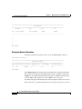
Displaying Sensor Information
To display information about the sensors, enter the show sensor command.
SFS-7000P# show sensor
================================================================================
Sensor Information
================================================================================
sensor oper-status oper-code temperature(c) alarm-temp(c)
shutdown-temp(c)
-------------------------------------------------------------------------------1/1
up
normal
29
65
73
SFS-7000P#
In the Temperature field, the internal system temperature is displayed in Celsius.
The system’s maximum external ambient temperature is 30 degrees Celsius (0 –
10,000 feet). Acceptable internal temperature ranges are 30 degrees Celsius above
external ambient, plus 1 degree for every 1,000 feet above sea level.
A warning will appear if the temperature reaches 65 degrees Celsius (at sea level).
The system reboots at an internal temperature of 75 degrees Celsius (at sea level).
Cisco SFS 7000P Hardware Installation Guide
4-8
OL-9167-01 Rev. A0
C H A P T E R
5
Hardware Diagnostic Tests
This chapter describes how to run diagnostic tests on the Cisco SFS 7000P switch
hardware. This chapter contains the following sections:
•
About Diagnostic Tests, page 5-1
•
Displaying Hardware Errors, page 5-9
About Diagnostic Tests
Hardware diagnostic tests can be performed through the CLI or the Element
Manager GUI. For instructions on how to run test with the Java GUI, see the Cisco
SFS 7000 Series Product Family Element Manager User Guide. A power-on self
test (POST) is run automatically on various components at power-on.
The following sections refer to running tests and displaying test with the CLI. For
complete diagnostic command information, refer to the Command Line Reference
Guide.
LED Tests
LED tests allow you to set a particular LED to blink in a specific way so that you
can more easily identify a specific component in a rack.
Cisco SFS 7000P Hardware Installation Guide
OL-9167-01 Rev. A0
5-1
Chapter 5
Hardware Diagnostic Tests
Running Card Tests
Self-Tests
The Cisco SFS 7000P switch provides the following diagnostic tests:
•
Card Self-Test
•
Fan Self-Test
•
Power Supply Self-Test
Running Card Tests
The term “cards” in this section refers to fabric controllers, management I/O
modules, node cards, and the chassis ID module. Fans and power supplies are not
included in the card tests; they can be tested through the standard chassis test or
as individual components.
The following tests are available to locate and diagnose one or more cards in the
chassis:
•
LED
•
Self-test
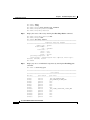
Running a Card Self-Test
To perform a diagnostic self-test on a card, follow these steps:
Step 1
Enter the diag card number command.
SFS-7000P> enable
SFS-7000P# config
SFS-7000P(config)# diag card 11
SFS-7000P(config-diag-card-11)# test self-test
SFS-7000P(config-diag-card-11)# start
SFS-7000P(config-diag-card-11)# exit
SFS-7000P(config)# exit
Note
You can stop the diagnostic self-test at any time by entering the stop command.
Cisco SFS 7000P Hardware Installation Guide
5-2
OL-9167-01 Rev. A0
Chapter 5
Hardware Diagnostic Tests
Running Chassis Tests
Step 2
Exit the test to view the progress of the test.
The test takes approximately 5 to 8 minutes.
SFS-7000P# show diagnostic card 1
======================================================================
Diagnostic Tests For Cards
======================================================================
test : self-test
slot-id : 1
iterations : 1
action : start
result : success
percentage-completed : 100
result-string : Card Test Completed, Final report :
Passed=1, Failed=0, Total=1
Step 3
If the test fails, enter the more syslog:hwif_log command to see the log
information.
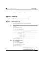
Running Chassis Tests
The following tests are available to locate and diagnose the chassis:
•
LED
•
Standard
•
Extended
•
Extended Memory
Running a Chassis Standard Test
The chassis standard test runs a diagnostic test on all cards in the chassis. To
perform a chassis standard test on a card, follow these steps:
Step 1
Start the test by entering the diag chassis test standard command and the start
command.
Cisco SFS 7000P Hardware Installation Guide
OL-9167-01 Rev. A0
5-3
Chapter 5
Hardware Diagnostic Tests
Running Chassis Tests
SFS-7000P> enable
SFS-7000P# config
SFS-7000P(config)# diag chassis test standard
SFS-7000P(config-diag-chassis)# start
SFS-7000P(config-diag-chassis)#
Step 2
Display the status of the test by entering the show diag chassis command.
SFS-7000P(config-diag-chassis)# exit
SFS-7000P(config)# exit
SFS-7000P# show diag chassis
======================================================================
Diagnostic Tests For Chassis
======================================================================
module-type : chassis
module-number : 1
test : standard
iterations : 1
option : none
action : start
result : success
percentage-completed : 100
result-string : Standard System Test Completed, Final report :
Passed=1, Failed=0, Total=1
SFS-7000P#
Step 3
Display any errors on individual components by entering the show diag post
command.
SFS-7000P-1# show diag post
======================================================================
Post Status
======================================================================
fru-slot
post-status
post-error
---------------------------------------------------------------------card(1)
failed
_FRU_LIM_CARDTYPE_ERR
card(3)
failed
_FRU_SEEPROM_PROGRAM_ERR
card(5)
passed
none
card(6)
passed
none
card(7)
passed
none
card(8)
passed
none
card(9)
passed
none
card(11)
failed
_FRU_POWER_CONTROLLER_CONFIG_ERR
card(12)
passed
none
card(13)
passed
none
card(15)
passed
none
card(16)
passed
none
card(17)
passed
none
Cisco SFS 7000P Hardware Installation Guide
5-4
OL-9167-01 Rev. A0
Chapter 5
Hardware Diagnostic Tests
Running Fan Tests
fan(1)
passed
none
Running Fan Tests
The following sections describes the fan module tests:
Running a Self-Test on a Fan
To perform a diagnostic self-test on a fan, follow these steps:
Step 1
Identify the number of the fan you want to diagnose, if you do not already know
the number.
Enter the show fan command.
SFS-7000P# show diagnostic fan
======================================================================
Diagnostic Tests For Fan
======================================================================
module-type : fan
module-number : 2
test : self-test
iterations : 1
action : start
result : success
percentage-completed : 100
result-string : Fan Self Test Completed, Final report :
Passed=1, Failed=0, Total=1
Step 2
Enter the diag fan id command.
SFS-7000P# config
SFS-7000P(config)# diag fan 1
SFS-7000P(config-diag-fan-1)# test self-test
SFS-7000P(config-diag-fan-1)# start
SFS-7000P(config-diag-fan-1)# exit
SFS-7000P(config)# exit
SFS-7000P# show diag fan
======================================================================
Diagnostic Tests For Fan
Cisco SFS 7000P Hardware Installation Guide
OL-9167-01 Rev. A0
5-5
Chapter 5
Hardware Diagnostic Tests
Running Fan Tests
======================================================================
module-type : fan
module-number : 1
test : self-test
iterations : 1
action : start
result : in-progress
percentage-completed : 70
result-string : Self Test, Current report : In progress...
SFS-7000P#
Step 3
Display the progress of the test by entering the show diag fan command.
SFS-7000P(config-diag-fan-1)# exit
SFS-7000P(config)# exit
SFS-7000P# show diag fan
======================================================================
Diagnostic Tests For Fan
======================================================================
module-type : fan
module-number : 1
test : self-test
iterations : 1
action : start
result : in-progress
percentage-completed : 70
result-string : Self Test, Current report : In progress...
SFS-7000P#
Step 4
Display any errors that appear in the result string by entering the show diag
fru-error command.
SFS-7000P# show diag fru-error
============================================================
Fru-Error
============================================================
fru-slot
fru-error
-----------------------------------------------------------card(1)
none
card(2)
none
card(7)
none
card(8)
none
card(9)
none
card(10)
none
card(11)
none
card(12)
none
card(13)
none
card(14)
none
card(15)
none
Cisco SFS 7000P Hardware Installation Guide
5-6
OL-9167-01 Rev. A0
Chapter 5
Hardware Diagnostic Tests
Running Power Supply Tests
card(17)
fan(1)
fan(2)
Step 5
none
none
none
Reboot the chassis when the self-test is complete.
SFS-7000P# reload
System configuration is modified. Save? [yes(default) | no | filename]
y
Proceed with reload? [yes(default) | no] y
Running Power Supply Tests
The following tests are available to locate and diagnose fan modules:
•
LED
•
Self-Test
Running a LED Test on the Power Supply
You can use the LED test to identify a specific power supply by entering these
commands:
SFS-7000P> enable
SFS-7000P# config
SFS-7000P(config)# diag power-supply 1
SFS-7000P(config-diag-power-supply-1)# test led
SFS-7000P(config-diag-power-supply-1)# start
SFS-7000P(config-diag-power-supply-1)# stop
SFS-7000P(config-diag-power-supply-1)#
Running a Self-Test on a Power Supply
To perform a diagnostic self-test on a power supply, follow these steps:
Step 1
Determine the ID of the power supply that you want to diagnose, if you do not
already know the number.
Cisco SFS 7000P Hardware Installation Guide
OL-9167-01 Rev. A0
5-7
Chapter 5
Hardware Diagnostic Tests
Running Power Supply Tests
Enter the show power-supply command.
SFS-7000P# show power-supply
=====================================================================
Power-supply Information
=====================================================================
ps
type
admin-status oper-status
utilization
voltage
--------------------------------------------------------------------1
AC
up
up
n/a
48
2
AC
up
up
15
47
Step 2
Specify the type of test (self-test is chosen by default) by entering the diag
power-supply id command.
SFS-7000P> enable
SFS-7000P# config
SFS-7000P(config)# diag power-supply 2
SFS-7000P(config-diag-power-supply-2)# test self-test
Step 3
Start the test.
SFS-7000P(config-diag-power-supply-2)# start
Step 4
Display the progress of the test by entering the show diag fan command.
SFS-7000P(config-diag-power-supply-2)# exit
SFS-7000P(config)# exit
SFS-7000P# show diagnostic power-supply
======================================================================
Diagnostic Tests For Power Supply
======================================================================
module-type : power-supply
module-number : 2
test : self-test
iterations : 1
action : start
result : success
percentage-completed : 100
result-string : Power Supply Self Test Completed, Final
report : Passed=1, Failed=0, Total=1
Step 5
Display any errors that appear in the result string by entering the show diag
fru-error command.
SFS-7000P# show diag fru-error
================================================================
Fru-Error
================================================================
Cisco SFS 7000P Hardware Installation Guide
5-8
OL-9167-01 Rev. A0
Chapter 5
Hardware Diagnostic Tests
Displaying Hardware Errors
fru-slot
fru-error
---------------------------------------------------------------card(9)
none
card(10)
none
card(11)
none
card(12)
none
card(13)
none
card(14)
none
card(15)
none
card(17)
none
fan(1)
none
fan(2)
none
fan(3)
none
fan(4)
none
power-supply(1) none
power-supply(2) none
SFS-7000P#
Step 6
Reboot the chassis when the self-test is complete.
SFS-7000P# reload
System configuration is modified. Save? [yes(default) | no | filename]
y
Proceed with reload? [yes(default) | no] y
Displaying Hardware Errors
To display POST results, non-fatal errors that can are recovered, informational
logging (such as firmware updates), and hardware errors:
To display hardware errors, follow these steps:
Step 1
Locate the /topspin/log/hwif_log file by entering the more syslog:hwif_log
command.
SFS-7000P>
SFS-7000P#
Thu Mar 4
Thu Mar 4
Thu Mar 4
Thu Mar 4
Thu Mar 4
Thu Mar 4
enable
more syslog:hwif_log
10:57:49 2004: POST: SEEPROM: PASSED
10:57:49 2004: POST: FPGA: PASSED
10:57:49 2004: POST: SUMMIT: PASSED
10:57:50 2004: POST: RTC: PASSED
10:57:54 2004: POST: FAN: PASSED
10:57:54 2004: card_startup.x : card is starting up
Cisco SFS 7000P Hardware Installation Guide
OL-9167-01 Rev. A0
5-9
Chapter 5
Hardware Diagnostic Tests
Displaying Hardware Errors
Thu Mar 4 10:57:54
Thu Mar 4 10:58:16
Thu Mar 4 19:01:55
Thu Mar 4 19:01:55
Thu Mar 4 19:01:55
Thu Mar 4 19:01:56
Thu Mar 4 19:02:00
Thu Mar 4 19:02:00
Thu Mar 4 19:02:00
<output truncated>
2004:
2004:
2004:
2004:
2004:
2004:
2004:
2004:
2004:
Anafa2Init: a2update set to IGNORE
Anafa2 POST: firmware check PASSED
POST: SEEPROM: PASSED
POST: FPGA: PASSED
POST: SUMMIT: PASSED
POST: RTC: PASSED
POST: FAN: PASSED
card_startup.x : card is starting up
Anafa2Init: a2update set to IGNORE
You can also view POST error codes with the show diagnostic post command.
This command displays the results of each POST that executed at power-on.
SFS-7000P# show diagnostic post
======================================================================
Post Status
======================================================================
fru-slot
post-status
error-codes
------------------------------------------------------------------------------card(1)
failed
1:0:0:0
fan(1)
passed
0:0:0:0
fan(2)
passed
0:0:0:0
power-supply(1) passed
0:0:0:0
Step 2
Display FRU errors on your Cisco SFS 7000P switch by entering the show
diagnostic fru-error command.
SFS-7000P# show diagnostic fru-error
======================================================================
Fru-Error
======================================================================
fru-slot
fru-error
------------------------------------------------------------------------------card(1)
_FRU_POWER_CONTROLLER_CONFIG_ERR
fan(1)
none
fan(2)
none
power-supply(1) none
Table 5-1 lists the hardware errors that are logged for the power supply.
Cisco SFS 7000P Hardware Installation Guide
5-10
OL-9167-01 Rev. A0
Chapter 5
Hardware Diagnostic Tests
Displaying Hardware Errors
Table 5-1
Cisco SFS 7000P Power Supply Errors
Error Number
Description
1
Power supply DC fail error
2
Power supply fan fail error
3
Power supply I2C communication error
Cisco SFS 7000P Hardware Installation Guide
OL-9167-01 Rev. A0
5-11
Chapter 5
Hardware Diagnostic Tests
Displaying Hardware Errors
Cisco SFS 7000P Hardware Installation Guide
5-12
OL-9167-01 Rev. A0
A P P E N D I X
A
Specifications and Compliance
Certifications
This appendix describes the Cisco SFS 7000P switch specifications and
compliance certifications.
Chassis and Management Interface
Table A-1 lists the general specifications for the chassis.
Table A-1
Chassis and Management General Specifications
Item
Specification
Operating temperature
0 to 45°C
Nonoperating temperature
-40 to 70°C
Operating temperature gradient
20°C max. per 60 minutes
Operating altitude
0 to 10,000 feet
Nonoperating altitude
0 to 40,000 feet
Operating humidity:
8 to 80% non-condensing
Nonoperating humidity:
5 to 90% RH at 65°C for 24 hours,
non-condensing
Operating humidity gradient
10% maximum per 60 minutes
Cisco SFS 7000P Hardware Installation Guide
OL-9167-01 Rev. A0
A-1
Appendix A
Table A-1
Specifications and Compliance Certifications
Chassis and Management General Specifications (continued)
Item
Specification
Operating shock
5 G max., 11 ms half-sine wave, 10 G max.
5 ms half-sine wave
Nonoperating shock
10G max., 11 ms half-sine wave.
Operating vibration, sinusoidal
0.25 G max., 3-200Hz 15 minutes
Nonoperating vibration, sinusoidal
0.50 G max., 3-200Hz 15 minutes
Nonoperating vibration, random
2.09 Grms, 3-axis, bottom/top, left/right,
front/back
Max. operating inclination
15 degrees
Physical Characteristics
Dimensions
1 RU, fits in standard 19-inch rack
Weight
Maximum weight is 22 pounds (10 kg)
Electrical Specifications
Table A-2 lists the electrical specifications for the chassis.
Table A-2
Electrical Specifications
Category
Specification
AC input
Auto-ranging 90 to 264 VAC, 47 to 63 Hz.
Power consumption
Less than 65 W
Cisco SFS 7000P Hardware Installation Guide
A-2
OL-9167-01 Rev. A0
INDEX
A
F
audience ix
fan
speed 4-6
C
fans
monitor 4-5
clock 1-5
remove 3-5
connections 1-2
show 4-7
connectivity
tab 4-5
configuring 2-3
conventions x
D
I
install
power supply/fan 3-2
diag card 5-2
diagram
topology sample 1-4
L
latency 1-5
LEDs 4-1
E
about 1-2
element manager
fan 4-3
health status 4-4
InfiniBand ports 4-2
summary tab 4-4
power supply 4-3
Cisco SFS 7000P Hardware Installation Guide
OL-9167-01 Rev. A0
IN-1
Index
requirements 2-5
M
monitor
S
LEDs 4-1
show sensor 4-8
mounting the chassis 2-6
sensors 4-6
serial console cable 2-3
show fan 4-7
show power-supply 5-8
O
show sensor 4-8
OperStatus 4-5
summary tab 4-4
P
T
power on the chassis 2-4
temperature
power supply
gradient A-1
monitor 4-5
monitor 4-6
remove 3-5
show 4-8
tab 4-5
topology
power supply/fan
sample 1-4
install 3-2
V
R
VPD 1-5
racking 2-6
real-time clock 1-5
Regulatory Compliance and Safety
Information xii
related documentation xvi
remove a power supply/fan 3-5
W
warnings
translations xii
Cisco SFS 7000P Hardware Installation Guide
IN-2
OL-9167-01 Rev. A0