1
CH A P T E R
55
Configuring a VoIP Network
This chapter describes how to configure a Voice-over-IP (VoIP) network on the Catalyst 6500 series
switches.
Note
While this chapter introduces a number of Cisco networking products that are related to VoIP, the
primary focus of the chapter is to provide configuration information for integrating the Catalyst 6500
series products into your VoIP network.
Note
For complete syntax and usage information for the commands that are used in this chapter, refer to the
Catalyst 6500 Series Switch Command Reference publication.
This chapter consists of these sections:
•
Hardware and Software Requirements, page 55-1
•
Understanding How a VoIP Network Works, page 55-2
•
Understanding How VLANs Work, page 55-8
•
Understanding How CDP and VoIP Work, page 55-10
•
Configuring VoIP on a Switch, page 55-10
•
Using SmartPorts, page 55-38
Hardware and Software Requirements
The hardware and software requirements for the Catalyst 6500 series switches and Cisco CallManager
are as follows:
•
Catalyst 4500 series, 5000 family, and Catalyst 6500 series switches running supervisor engine
software release 6.1(1) or later releases
•
Catalyst 4500 series and Catalyst 6500 series switches running supervisor engine software
release 8.2(1) or later releases for IEEE 802.3af compliance
•
Cisco CallManager release 3.0 or later releases
Catalyst 6500 Series Switch Software Configuration Guide—Release 8.7
OL-8978-02
55-1
Chapter 55
Configuring a VoIP Network
Understanding How a VoIP Network Works
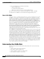
Understanding How a VoIP Network Works
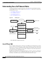
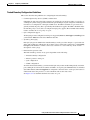
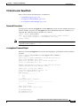
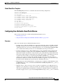
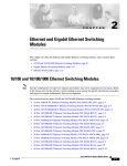
A telephony system built on an IP network instead of the traditional circuit-switched private branch
exchange (PBX) network is called an IP PBX system. (See Figure 55-1.) The system’s components are
described in these sections:
•
Cisco IP Phone 7960, page 55-2
•
Cisco CallManager, page 55-5
•
Access Gateways, page 55-5
•
How a Call Is Made, page 55-8
Figure 55-1
IP PBX System
Cisco CallManager
PSTN or PBX
IP cloud
Analog Trunk Gateway
Digital Trunk Gateway
(WS-X6608-T1/E1)
Analog stations
(phone, fax, modem)
Analog Station Gateway
(WS-X6624-FXS)
Voice Gateway 200
Analog stations
(phone, fax, modem)
PSTN or PBX
10/100BASE-TX Module *
10/100BASE-TX Module
(WS-X6348-RJ45V)
WS-PWR-PNL
IP phone
PC
IP phone
PC
* Catalyst 4000, 5000, and 6000 10/100 modules
38202
Catalyst 6500 series switches
Cisco IP Phone 7960
The Cisco IP Phone 7960 provides the connectivity to the IP PBX system. The IP phone has two RJ-45
jacks for connecting to the external devices: a LAN-to-phone jack and a PC-to-phone jack. The jacks use
either Category 3 or Category 5 unshielded twisted-pair (UTP) cable. The LAN-to-phone jack is used to
connect the phone to the LAN using a crossover cable; a workstation or a PC can be connected to the
PC-to-phone jack using a straight-through cable.
The inline power is designed to work in cables from Category 3, Category 4, Category 5, and later up to
100 meters. The inline power works with IBM Token Ring STP cable of 100 meters when used with a
Token Ring to Fast Ethernet adapter (LanTel Silver Bullet SB-LN/VIP-DATA adapter).
Catalyst 6500 Series Switch Software Configuration Guide—Release 8.7
55-2
OL-8978-02
Chapter 55
Configuring a VoIP Network
Understanding How a VoIP Network Works
The IP phone is Dynamic Host Configuration Protocol (DHCP) capable. Optionally, you can program
the IP phone with a static IP address.
The IP phone can be powered by the following sources:
•
External power source—Optional transformer and power cord for connecting to a standard wall
receptacle.
•
Ethernet switching modules with the voice daughter card installed—Provides the inline power to the
IP phone.
•
WS-PWR-PNL (inline-power patch panel)—Provides the inline power to the IP phone. The inline
patch panel allows the IP phone to connect to existing Catalyst 4500 series, 5000 family, and
6500 series 10/100BASE-TX switching modules.
•
WS-PWR-PNL (inline-power patch panel)—Provides the inline power to the IP phone. The inline
patch panel allows the IP phone to connect to existing Catalyst 4500 series, 5000 family, and
6500 series 10/100BASE-TX switching modules.
•
WS-X6148-RJ-45 10/100 switching module with either the WS-F6K-VPWR inline-power
field-upgrade module or the WS-F6K-FE48-AF inline-power field-upgrade module—Provides the
inline power to the IP phone.
•
WS-X6148-RJ-21 10/100 switching module with either the WS-F6K-VPWR inline-power
field-upgrade module or the WS-F6K-FE48-AF inline-power field-upgrade module—Provides the
inline power to the IP phone.
•
WS-X6148X2-RJ-45 10/100 switching module with the WS-F6K-FE96-AF inline-power
field-upgrade module—Provides the inline power to the IP phone.
•
WS-X6148X2-RJ-21 10/100 switching module with the WS-F6K-FE96-AF inline-power
field-upgrade module—Provides the inline power to the IP phone.
•
WS-6548-GE-TX Gigabit Ethernet switching module with either the WS-F6K-VPWR-GE
inline-power field-upgrade module or the WS-F6K-GE48-AF inline-power field-upgrade
module—Provides the inline power to the IP phone.
•
WS-6148-GE-TX Gigabit Ethernet switching module with either the WS-F6K-VPWR-GE
inline-power field-upgrade module or the WS-F6K-GE48-AF inline-power field-upgrade
module—Provides the inline power to the IP phone.
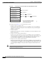
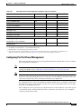
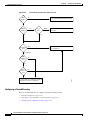
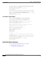
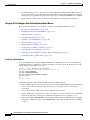
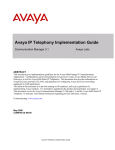
Figure 55-2 shows how to connect the Cisco IP Phone 7960 and PCs to the Catalyst 6500 series switch.
Catalyst 6500 Series Switch Software Configuration Guide—Release 8.7
OL-8978-02
55-3
Chapter 55
Configuring a VoIP Network
Understanding How a VoIP Network Works
Figure 55-2
Connecting the Cisco IP Phone 7960 to the Catalyst 6500 Series Switch
10/100BASE-TX Module
(WS-X6348-RJ45V)
*
10/100BASE-TX Module
(WS-X6348-RJ45V)
*
10/100BASE-TX Module
(WS-X6348-RJ45V)
*
10/100BASE-TX Module
(WS-X6348-RJ45V)
*
IP phone (Example 1)
PC (Example 2)
IP phone
PC (Example 3)
IP phone
IP phone
PC (Example 4)
Gigabit Ethernet Module with *
Inline power daughter card
Catalyst 6500 series switches
* Or any Catalyst 4000, 5000, and 6000
10/100 module using the inline-power
patch panel (WS-PWR-PNL)
38203
(WS-6548-GE-TX + WS-F6K-VPWR)
The examples shown in Figure 55-2 are described in detail as follows:
•
Example 1: Single Cisco IP Phone 7960
Example 1 shows one IP phone that is connected to the 10/100 port on the Catalyst 6500 series
switch. The PC-to-phone jack on the phone is not used. The phone can be powered through the
10/100 port or wall powered.
•
Example 2: Single PC
Example 2 shows one PC that is connected to the 10/100 port on the Catalyst 6500 series switch.
The PC is wall powered.
•
Example 3: One Cisco IP Phone 7960 and One PC
Example 3 shows one IP phone that is connected to the 10/100 port on the Catalyst 6500 series
switch and one PC that is connected to the PC-to-phone jack on the phone. The PC behaves as if it
is connected directly to the 10/100 port on the Catalyst 6500 series switch. The phone can be
powered through the 10/100 port or wall powered. The PC must be wall powered.
•
Example 4: Two Cisco IP Phone 7960s and One PC
Example 4 shows two IP phones that are connected to the 10/100 port on the Catalyst 6500 series
switch and one PC that is connected to the PC-to-phone jack on the phone. The PC behaves as if it
is connected directly to the 10/100 port on the Catalyst 6500 series switch. The first phone can be
powered through the 10/100 port or wall powered. The second phone and the PC must be wall
powered.
Note
For more information on configuring the Cisco IP phones and third-party vendor phones, refer to the
documentation that shipped with the phone.
Catalyst 6500 Series Switch Software Configuration Guide—Release 8.7
55-4
OL-8978-02
Chapter 55
Configuring a VoIP Network
Understanding How a VoIP Network Works
Cisco CallManager
Cisco CallManager is an open and industry-standard call processing system; its software runs on a
Windows NT server and sets up and tears down the calls between the phones, integrating traditional PBX
functionality with the corporate IP network. Cisco CallManager manages the components of the IP PBX
system, the phones, the access gateways, and the resources for such features as call conferencing and
media mixing. Each Cisco CallManager manages the devices within its zone and exchanges information
with the Cisco CallManager in charge of another zone to make the calls possible across multiple zones.
Cisco CallManager can work with the existing PBX systems to route a call over the Public Switched
Telephone Network (PSTN).
Note
For information on configuring Cisco CallManager to work with the IP devices that are described in this
chapter, refer to the Cisco CallManager Administration Guide, the Configuration Notes for Cisco
CallManager, and the Cisco CallManager Remote Serviceability Users Guide publications.
Access Gateways
The access gateways allow the IP PBX system to talk to the existing PSTN or PBX systems. The access
gateways consist of analog station gateways, analog trunk gateways, digital trunk gateways, and a
converged voice gateway.
These sections describe the gateways:
•
Analog Station Gateway, page 55-5
•
Analog Trunk Gateway, page 55-6
•
Digital Trunk Gateway, page 55-6
•
Converged Voice Gateway, page 55-7
Analog Station Gateway
The Catalyst 6500 series 24-port Foreign Exchange Station (FXS) analog interface module allows the
plain old telephone service (POTS) phones and fax machines to connect to the IP PBX network. The
analog station gateway behaves like the PSTN side for the POTS equipment. It requires an IP address,
is registered with Cisco CallManager in its domain, and is managed by Cisco CallManager.
To configure the analog station interfaces, see the “Configuring VoIP on a Switch” section on
page 55-10. The module features are listed in Table 55-1.
Table 55-1
24-Port FXS Analog Interface Module Features
Digital Signal Processing Per Port
G.711 and G.729 voice encoding
Silence suppression; voice activity detection
Comfort noise generation
Ringer, software programmable frequency and cadence, based on country
DTMF1 detection
Signaling, loop start
Catalyst 6500 Series Switch Software Configuration Guide—Release 8.7
OL-8978-02
55-5
Chapter 55
Configuring a VoIP Network
Understanding How a VoIP Network Works
Table 55-1
24-Port FXS Analog Interface Module Features (continued)
Digital Signal Processing Per Port
Line echo cancellation (32 ms)
Impedance (600 ohms)
Programmable analog gain, signaling timers
Fax pass-through
SPAN2 or port mirroring support
FXS Interface Features
Address signaling formats: In-band DTMF
Signaling formats: Loop start
Ringing tone: Programmable
Ringing voltage: Programmable, based on country
Ringing frequency: Programmable, based on country
Distance: 500-ohms maximum loop
1. DTMF = dual tone multifrequency
2. SPAN = Switched Port Analyzer
Analog Trunk Gateway
The Cisco access analog trunk gateways allow the IP PBX to connect to the PSTN or PBX. The gateway
supports up to eight trunks to the PSTN and appears like a phone to the trunk lines coming from the
PSTN. Using this gateway, the IP PBX places an IP call through the PSTN. Similar to the analog station
gateway, the analog trunk gateway provides line echo cancellation and dual tone multifrequency
(DTMF) tone generation and detection. The analog trunk gateway does not provide the ring voltage as
it is not connected to the POTS end devices such as the POTS phones or fax machines. The analog trunk
gateway requires an IP address, is registered with Cisco CallManager in its domain, and is managed by
Cisco CallManager.
To configure the analog trunk gateways, refer to the documentation that shipped with the gateway.
Digital Trunk Gateway
The Catalyst 6500 series 8-port T1/E1 PSTN interface module can support both digital T1/E1
connectivity to the PSTN or transcoding and conferencing. The module requires an IP address, is
registered with Cisco CallManager in its domain, and is managed by Cisco CallManager.
The module software is downloaded from a TFTP server. Depending upon which software you
download, the ports can serve as the T1/E1 interfaces or the ports support transcoding and conferencing.
The transcoding and conferencing functions are mutually exclusive. For every transcoding port in use,
one less conferencing port is available and vice versa.
To configure the 8-port T1/E1 PSTN interfaces, see the “Configuring VoIP on a Switch” section on
page 55-10. The module features are listed in Table 55-2.
Catalyst 6500 Series Switch Software Configuration Guide—Release 8.7
55-6
OL-8978-02
Chapter 55
Configuring a VoIP Network
Understanding How a VoIP Network Works
Table 55-2
8-Port T1/E1 PSTN Interface Module Features
Digital Signal Processing Per T1/E1 Port
G.711 to G.723 and G.729a transcoding (maximum of 8 x 32 channels of transcoding)
Conference bridging, meet-me, and ad-hoc conference modes (maximum of 8 x 16 channels of
conferencing)
Comfort noise generation
Fax pass-through
Silence suppression, voice activity detection
Line echo cancellation
Common channel signaling
For T1: 23 DS0 channels for voice traffic; 24th channel is used for signaling
For E1: 29 DS0 channels for voice traffic; 16th channel is reserved for signaling
Any channel can be configured for common channel signaling
ISDN Primary Rate Interface signaling: Each interface supports 23 channels for T1 and 30 channels
for E1. The default mode is for the 24th T1 channel or 16th E1 channel to be reserved for signaling.
Both network side and user side operation modes are supported.
T1 binary 8-zero substitution/alternate mark inversion (B8ZS/AMI) line coding, u-law or a-law
coding
E1 HDB3 line coding
T1 line bit rate: 1.544 Mbps
E1 line bit rate: 2.048 Mbps
T1 line code: AMI, B8ZS
E1 line code: HDB3
Framing format: D4 superframe and extended superframe
Link Management
FDL1 is a link management protocol that is used to help diagnose problems and gather statistics on
T1 lines
1. FDL = Facilities Data Link
Converged Voice Gateway
The Cisco Voice Gateway 200 (VG200) allows you to connect the standard POTS phones (connected
directly to the gateway or anywhere on the PSTN) with Cisco IP or any H.323-compliant telephony
devices. When used with Cisco CallManager, the VG200 functions as a Media Gateway Control Protocol
(MGCP) gateway. The Cisco VG200 provides a 10/100BASE-T Ethernet port for connection to the data
network. The following telephony connections are also available:
•
One to four Foreign Exchange Office (FXO) ports for connecting to a central office or PBX
•
One to four FXS ports for connecting to POTS telephony devices
Catalyst 6500 Series Switch Software Configuration Guide—Release 8.7
OL-8978-02
55-7
Chapter 55
Configuring a VoIP Network
Understanding How VLANs Work
•
One or two T1 digital ports for connecting to the following:
– PSTN using FXO emulation
– T1 channel bank using FXS emulation
– PBX through a trunk (tie) line using ear and mouth (E&M) emulation
These ports can be used to integrate a VoIP network with POTS devices, PBXs, or the PSTN.
To configure the Cisco VG200, refer to the documentation that shipped with the gateway.
How a Call Is Made
An IP phone connects to a LAN either through a hub port or a switch port. The IP phone boots up and
uses DHCP to get its IP address and the IP address of its TFTP file server. The IP phone uses its IP
address to talk to the TFTP server and gets its configuration file. The configuration file includes the IP
address of the phone’s Cisco CallManager(s). The phone then talks with Cisco CallManager and
registers itself. Each time a phone boots up, it might get a different IP address. Cisco CallManager knows
how to associate a consistent user phone number to a particular phone by using the MAC address of the
phone. Cisco CallManager always maintains a table mapping the phone MAC address and phone
number. Each time a phone registers, the table is updated with the new IP address. During the
registration, Cisco CallManager downloads the key pad template and the feature capability for the
phone. It tells the phone which run-time image it should use. The phone then goes to the TFTP server to
get its run-time image. Each phone has a dedicated TCP connection to Cisco CallManager called the
control channel. All control information, such as key pressing, goes from the phone to Cisco
CallManager through this channel. Instructions to generate ring tone, busy tone, and so on comes from
Cisco CallManager to the phone through this channel.
Cisco CallManager stores the IP-address-to-phone-number mapping (and vice versa) in its tables. When
a user wants to call another user, the user keys in the called party’s phone number. Cisco CallManager
translates the phone number to an IP address and generates an IP packet version of the ring tone to the
called IP phone through the TCP connection. When the called IP phone receives the packet, it generates
a ring tone. When the user picks up the phone, Cisco CallManager instructs the called IP phone to start
talking with the calling party and removes itself from the loop. From this point on, the call goes between
the two IP phones through the Real-Time Transport Protocol (RTP) which runs over the User Datagram
Protocol (UDP). Because the voice packets are sensitive to delays, TCP is not suitable for voice
transmission because the timeouts and retries increase the delay between the packets. When any change
occurs during the call due to a feature being pressed on one of the phones, or one of the users hanging
up or pressing the flash button, the information goes to Cisco CallManager through the control channel.
If a call is made to a number outside of the IP PBX network, Cisco CallManager routes the call to an
analog or digital trunk gateway which routes it to the PSTN.
Understanding How VLANs Work
This section describes the native VLANs and the auxiliary VLANs. This section uses the following
terminology:
•
Auxiliary VLAN—Separate VLAN for IP phones
•
Native VLAN—Traditional VLAN for data
•
Auxiliary VLAN ID—VLAN ID of an auxiliary VLAN
•
Native VLAN ID—VLAN ID of a native VLAN
Catalyst 6500 Series Switch Software Configuration Guide—Release 8.7
55-8
OL-8978-02
Chapter 55
Configuring a VoIP Network
Understanding How VLANs Work
Note
For more information about the VLANs, see Chapter 11, “Configuring VLANs.”
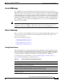
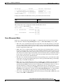
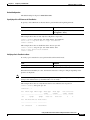
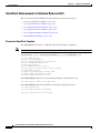
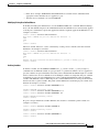
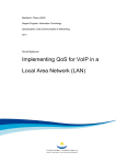
Figure 55-3 shows how to connect a Cisco IP Phone 7960 to a Catalyst 6500 series switch.
Figure 55-3
Switch-to-Phone Connections
Cisco IP Phone 7960
Phone
ASIC
Catalyst switch
Workstation/PC
P2
P1
3-port
switch
P3
Access
port
38204
10/100 module
When the IP phone connects to a 10/100 port on the Catalyst 6500 series switch, the access port
(PC-to-phone jack) of the IP phone can be used to connect a PC.
The packets to and from the PC and to and from the phone share the same physical link to the switch and
the same port of the switch. The various configurations are shown in the “Cisco IP Phone 7960” section
on page 55-2).
Introducing the IP-based phones into the existing switch-based networks raises the following issues:
•
The current VLANs might be configured on an IP subnet basis, and additional IP addresses might
not be available to assign the phone to a port so that it belongs to the same subnet as other devices
(PC) that are connected to the same port.
•
The data traffic present on the VLAN supporting phones might reduce the quality of the VoIP traffic.
You can resolve these issues by isolating the voice traffic onto a separate VLAN on each of the ports that
are connected to a phone. The switch port that is configured for connecting a phone would have separate
VLANs that are configured for carrying the following:
•
Voice traffic to and from the IP phone (auxiliary VLAN)
•
Data traffic to and from the PC that is connected to the switch through the access port of the IP phone
(native VLAN)
Isolating the phones on a separate, auxiliary VLAN increases the quality of the voice traffic and allows
a large number of phones to be added to an existing network where there are not enough IP addresses.
A new VLAN means a new subnet and a new set of IP addresses.
Catalyst 6500 Series Switch Software Configuration Guide—Release 8.7
OL-8978-02
55-9
Chapter 55
Configuring a VoIP Network
Understanding How CDP and VoIP Work
Understanding How CDP and VoIP Work
Cisco Discovery Protocol (CDP) was enhanced in software release 8.1(1) to facilitate backward
compatibility with the newer, higher-powered Cisco IP phones. With this enhanced CDP, a Cisco IP
phone can negotiate its power requirements to the switch within the CDP packet. The switch uses this
information to ensure that it does not oversubscribe the available power.
We recommend that you enable CDP on the switch so that the switch can correctly detect and supply
power to the IP phones that are connected to it. CDP is enabled on the Catalyst 6500 series switches by
default; however, you should confirm that CDP is enabled when setting up your VoIP network. For more
information on CDP, see Chapter 31, “Configuring CDP.”
Configuring VoIP on a Switch
This section describes the command-line interface (CLI) commands and the procedures that are used to
configure the Catalyst 6500 series switch for VoIP operation:
•
Voice-Related CLI Commands, page 55-10
•
Configuring Per-Port Power Management, page 55-11
•
Configuring the Auxiliary VLANs on Catalyst LAN Switches, page 55-20
•
Configuring the Access Gateways, page 55-23
•
Displaying the Active Call Information, page 55-29
•
Configuring QoS in the Cisco IP Phone 7960, page 55-31
•
Configuring a Trusted Boundary to Ensure Port Security, page 55-33
Note
For information on using automatic voice configuration, see the “Using SmartPorts” section on
page 55-38.
Note
You must enable CDP on the Catalyst 6500 series switch port that is connected to the IP phone in order
to communicate the auxiliary VLAN ID, per-port power management details, and quality of service
(QoS) configuration information.
Voice-Related CLI Commands
Table 55-3 lists the CLI commands that are described in the configuration procedures.
Table 55-3
Voice-Related CLI Command Module and Platform Support
CLI Commands
Ethernet Module1
WS-X6608-T1/E12
WS-X6624-FXS3
Inline-power related commands
set port inlinepower
X4
set inlinepower defaultallocation
This is a switch-level command and does not affect the
individual modules.
show port inlinepower
X
Catalyst 6500 Series Switch Software Configuration Guide—Release 8.7
55-10
OL-8978-02
Chapter 55
Configuring a VoIP Network
Configuring VoIP on a Switch
Table 55-3
Voice-Related CLI Command Module and Platform Support (continued)
CLI Commands
Ethernet Module1
WS-X6608-T1/E12
WS-X6624-FXS3
show environment power
X
X
X
set port voice interface
X
X
show port voice interface
X
X
X
X
Voice-related commands
set port auxiliaryvlan
X/X
show port auxiliaryvlan
X/X
show port voice
X
show port voice fdl
X
show port voice active
X
X
X
QoS commands related to voice
set port qos mod/port cos-ext
X/X
set port qos mod/port trust-ext
show port qos
X/X
1. Ethernet Module = Ethernet switching module with voice daughter card.
2. WS-X6608-T1 and WS-X6608-E1 = 8-port T1/E1 ISDN PRI modules.
3. WS-X6624-FXS = 24-port FXS analog station interface module.
4. X = Command supported on Catalyst 6500 series switch only; XX = Command supported on Catalyst 4500 series, 5000 family, and
6500 series switches. All modules that are listed in Table 55-3 are supported only on Catalyst 6500 series switches.
Configuring Per-Port Power Management
This section describes the per-port power management and the CLI commands that are used to configure
power management for IP phones.
Note
To determine the exact power requirements for your configuration to ensure that you are within the
system power budget, see the “Generating a System Status Report” section on page 22-16.
Note
This section applies to the Ethernet switching modules with the voice daughter card only. For
information on powering the IP phones that are connected to the other Ethernet switching modules, refer
to the Catalyst Family Inline-Power Patch Panel Installation Note publication.
For each IP phone that is connected to an Ethernet switching module with a voice daughter card installed,
the module allocates part of the available system power to power up and run the phone. You can apply
the power on an individual port basis.
Only one IP phone can be powered per port; the phone must be connected directly to the switch port. If
a second phone is daisy chained off the phone that is connected to the switch port, the second phone
cannot be powered by the switch.
Catalyst 6500 Series Switch Software Configuration Guide—Release 8.7
OL-8978-02
55-11
Chapter 55
Configuring a VoIP Network
Configuring VoIP on a Switch
This section describes the following topics:
•
Using show Commands to Display Module Type and Version Information, page 55-12
•
Power Management Modes, page 55-13
•
Phone Detection Summary, page 55-16
•
Setting the Power Mode of a Port or a Group of Ports, page 55-17
•
Setting the Default Power Allocation, page 55-17
•
Setting the Inline Power Notification Threshold for a Module, page 55-18
•
Displaying the Power Status for Modules and Individual Ports, page 55-18
•
Displaying the Switch Power Environment for Modules, page 55-19
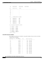
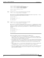
Using show Commands to Display Module Type and Version Information
To determine if the module has a voice daughter card installed, enter the show module command and
look at the “Sub” field. For example, in the following display, the 10/100BASE-TX module in slot 3 has
a voice daughter card.
To display the module status and information, perform this task in normal mode:
Task
Command
Display the module status and information.
show module [mod]
This example shows a submodule field that provides information about the submodules. The inline
power daughter card that is installed on module 3, as shown in the display, is WS-F6K-SVDB-FE, and
the inline power daughter card that is installed on module 6, as shown in the display, is
WS-F6K-VPWR-GE-TX.
Console>
Mod Slot
--- ---1
1
3
3
4
4
6
6
(enable) show module
Ports Module-Type
----- ------------------------2
1000BaseX Supervisor
48
10/100BaseTX Ethernet
48
10/100BaseTX Ethernet
48
10/100/1000BaseT Ethernet
Mod Module-Name
--- -------------------1
3
4
6
Model
------------------WS-X6K-SUP2-2GE
WS-X6548-RJ-45
WS-X6148-RJ45V
WS-X6148-GE-TX
Sub
--yes
yes
no
yes
Status
-------ok
ok
ok
ok
Serial-Num
----------SAD04460M9G
SAD0447099V
SAD061901FL
SAD0706025A
Mod MAC-Address(es)
--- -------------------------------------1
00-d0-c0-d4-04-4e to 00-d0-c0-d4-04-4f
00-d0-c0-d4-04-4c to 00-d0-c0-d4-04-4d
00-02-4a-30-88-00 to 00-02-4a-30-8b-ff
3
00-02-b9-ff-eb-70 to 00-02-b9-ff-eb-9f
4
00-00-00-00-00-00 to 00-00-00-00-00-2f
6
00-40-0b-ff-00-00 to 00-40-0b-ff-00-2f
Hw
Fw
Sw
------ ---------- ----------------1.1
6.1(2)
7.7(0.82-Eng)
0.203
1.3
0.304
6.3(1)
5.4(2)
7.2(1)
8.2(1)
7.7(0.81)
8.2(1)
Catalyst 6500 Series Switch Software Configuration Guide—Release 8.7
55-12
OL-8978-02
Chapter 55
Configuring a VoIP Network
Configuring VoIP on a Switch
Mod Sub-Type
--- ----------------------1
L3 Switching Engine II
3
IEEE InlinePower Module
6
Inline Power Module
Console> (enable)
Sub-Model
------------------WS-F6K-PFC2
WS-F6K-FE48-AF
WS-F6K-VPWR-GE
Sub-Serial
----------SAD044302EA
sasdfasdf
SAD070700GV
Sub-Hw
-----1.0
0.1
0.201
Sub-Sw
-----8.1(0)
8.1(0)
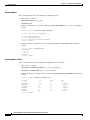
To display the module and submodule versions, perform this task in normal mode:
Task
Command
Display the module and submodule versions.
show version [mod]
This example shows how to display the module and submodule versions:
Console>
Mod Port
--- ---6
48
(enable) show version 6
Model
Serial #
Versions
------------------- ----------- -------------------------------------WS-X6148-GE-TX
SAD0706025A Hw :0.304
Fw :7.2(1)
Sw :8.1(0)
WS-F6K-VPWR-GE
SAD070700GV Hw :0.201
Sw :8.1(0)
Console>
Power Management Modes
Each port is configured through the CLI, SNMP, or a configuration file to be in one of the following
modes. The CLI command is set port inlinepower mod/port {{auto | static | limit} [wattage] | off}.
•
auto—Discovery is enabled and the supervisor engine directs the switching module to power up the
port only if the switching module discovers the phone. You can specify the maximum wattage that
is allowed on the port. If you do not specify a wattage, then the switch will deliver no more than the
hardware-supported maximum value.
•
static—Discovery is enabled and the supervisor engine directs the switching module to power up
the port to the wattage that you specify only if the switching module discovers the phone. You can
specify the maximum wattage that is allowed on the port. If you do not specify a wattage, then the
switch allows the hardware-supported maximum value. The maximum wattage, whether determined
by the switch or specified by you, is preallocated to the port. If the switch does not have enough
power for the allocation, the command will fail.
•
off—Discovery is disabled which prevents the port from providing power to an external device. If the
external device is wall-powered and the inline power is off, the port should still link up, join the bridge
group, and go to the STP forwarding state.
•
limit—Discovery is enabled. This mode provides you with the option to limit the power allocated for an
external device. If the wattage value that you specify with the limit keyword is less than the power
determined through IEEE classification, instead of denying power, the minimum of these two values is
allocated. If the device consumes more than the configured value, the port is shut down and an
appropriate syslog message is displayed. The limit keyword is not supported on all modules. To check if
the limit keyword is supported on a module, enter the show environment power mod command. If the
output of the command indicates support for per-port power monitoring, the mode is supported.
•
max-wattage—(Optional) The maximum power allowed on the port in either auto or static mode; valid
values are from 4000 to 15400 milliwatts.
Catalyst 6500 Series Switch Software Configuration Guide—Release 8.7
OL-8978-02
55-13
Chapter 55
Configuring a VoIP Network
Configuring VoIP on a Switch
Each port also has a status that is defined as one of the following:
•
on—Power is supplied by the port.
•
off—Power is not supplied by the port.
•
Power-deny—The supervisor engine does not have enough power to allocate to the port, or the
power that is configured for the port is less than the power that is required by the port; the power is
not being supplied by the port.
•
err-disable—The port is unable to provide the power to the connected device that is configured in
Static mode.
•
faulty—The port failed the diagnostics tests.
These sections provide the information on the IP phone power requirements and management:
•
Power Requirements, page 55-14
•
Available Power, page 55-15
•
Wall-Powered Phones, page 55-15
•
Powering Off the Phone, page 55-15
•
Phone Removal, page 55-15
•
High-Availability Support, page 55-16
Power Requirements
The IP phones may have different power requirements. Table 55-4 lists the power requirements for the
different classes of IP phones. The supervisor engine initially calculates the power allocation for each
port based on the per-port configuration, classification (IEEE only), and default power. When the correct
amount of power is determined from the CDP messaging with the Cisco IP Phone, the supervisor engine
reduces or increases the allocated power for any ports that are set to Auto mode. The allocated power is
not adjusted for ports that are set to Static mode.
For example, the default allocated power is 7 W for a Cisco IP Phone requiring 6.3 W. The supervisor
engine allocates 7 W for the Cisco IP Phone and powers it up. Once the Cisco IP Phone is operational,
it sends a CDP message with the actual power requirement to the supervisor engine. The supervisor
engine then decreases the allocated power to the required amount if the port is set to Auto mode. If the
port is set to Static mode, the supervisor engine allocates the wattage that you specified. If the port is set
to off, the supervisor engine does not allot any power to the port.
Table 55-4
Power Requirements for IP Phones
Phone Class
Required Power (W)
Cisco
6.3
Cisco + IEEE
7
Cisco High Power
15.4
Class 0 IEEE
15.4
Class 1 IEEE
4
Class 2 IEEE
7.0
Class 3
15.4
Class 4 Refer to Class 0
Reserved
Catalyst 6500 Series Switch Software Configuration Guide—Release 8.7
55-14
OL-8978-02
Chapter 55
Configuring a VoIP Network
Configuring VoIP on a Switch
Available Power
Table 55-5 lists the available power that can be supplied for each port for the voice daughter cards.
Table 55-5
Efficiency of Voice Daughter Cards
Daughter Card
Maximum Power
Per Port (W)
Efficiency
WS-F6K-PWR
6.3
100%
WS-F6K-VPWR-GE
6.3
89%
WS-F6K-GE48-AF
15
89%
WS-F6K-FE48-AF
15
89%
WS-F6K-FE96-AF
15
89%
For example, if the powered device requires 6.3 W, then the allotted power for that port using a daughter
card with 89 percent efficiency must be 6.3/(0.89) = 7 W. If you are using a voice daughter card with
100 percent efficiency, then the allotted power is 6.3 W.
Wall-Powered Phones
When a wall-powered phone is present on a switching module port, the switching module cannot detect
its presence. The supervisor engine discovers the phone through CDP messaging with the port. If the
phone supports the inline power (the supervisor engine determines this through CDP), and the mode is
set to Auto, Static, or Off, the supervisor engine does not attempt to power on the port. If a power outage
occurs, and the mode is set to Auto, the phone loses power, but the switching module discovers the phone
and informs the supervisor engine, which then applies the inline power to the phone. If a power outage
occurs, and the mode is set to Static, the phone loses power, but the switching module discovers the
phone and applies the preallocated inline power to the phone.
Powering Off the Phone
The supervisor engine can turn off power to a specific port by sending a message to the switching
module. The power for a port in Auto mode is then added back to the available system power. The power
for the ports in Static mode is not added back to the available system power. This situation occurs only
when you power off the phone through the CLI or SNMP.
Phone Removal
The switching module informs the supervisor engine if a powered phone is removed using a link-down
message. The supervisor engine then adds the allocated power for that port back to the available system
power.
In addition, the switching module informs the supervisor engine if an unpowered phone is removed.
Caution
When a phone cable is plugged into a port and the power is turned on, the supervisor engine has a
4-second timeout waiting for the link to go up on the line. During those 4 seconds, if the phone cable is
unplugged and a network device is plugged in, the device could be damaged. We recommend that you
wait at least 10 seconds between unplugging a device and plugging in a new device.
Catalyst 6500 Series Switch Software Configuration Guide—Release 8.7
OL-8978-02
55-15
Chapter 55
Configuring a VoIP Network
Configuring VoIP on a Switch
High-Availability Support
To support high availability during a failover from the active supervisor engine to the standby supervisor
engine, the per-port power management and phone status information is synchronized between the active
and standby supervisor engines.
The information to be synchronized (on a per-port basis) is the presence of a phone, the phone power
status (on, off, denied, or faulty), allocated power, device class, device type, device maximum power,
and device discovery. The active supervisor engine sends this information to the standby supervisor
engine, and the standby supervisor engine updates its internal data structures. When a switchover occurs,
the standby supervisor engine allocates the power to the modules and ports from the available power,
one module at a time. Once the power for each module has been allocated, the supervisor engine
allocates the power to the phones, beginning with the lowest slot number, until all inline powered ports
have been either powered on, off, or denied.
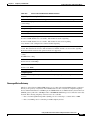
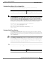
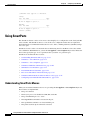
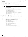
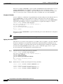
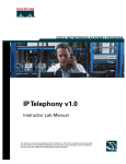
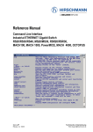
Phone Detection Summary
Figure 55-4 shows how the system detects a phone that is connected to a Catalyst 6500 series switch port.
Figure 55-4
Power Detection Summary
Catalyst Switch
10/100 module
Cisco phone
Switching module
discovers the phone.
10/100 module
Cisco phone
or third party phone.
Supervisor engine discovers
the phone through CDP and/or
IEEE.
Wall-power
Third party phone
without CDP.
10/100 module
Network
device
10/100 module
Network
device
Switching module will not discover
the phone because CDP is not
supported. However, the supervisor
engine detects the phone and powers
it up.
Phone is inserted but has not booted,
then phone is removed. A network
device is plugged in. Inline power
might damage the network device.
Cisco phone
or third party phone
with CDP.
Wall-power
Supervisor engine discovers the
phone through CDP and/or IEEE.
38205
10/100 module
Catalyst 6500 Series Switch Software Configuration Guide—Release 8.7
55-16
OL-8978-02
Chapter 55
Configuring a VoIP Network
Configuring VoIP on a Switch
Setting the Power Mode of a Port or a Group of Ports
To set the power mode of a port or a group of ports, perform this task in normal mode:
Task
Command
Set the power mode of a port or a group of ports. set port inlinepower mod/port {[auto | static]
[max-wattage] | off}
Note
If you configure the max-wattage values that are multiples of 500 on a Catalyst 6500 series switch with
the set port inlinepower mod/port static | auto max-wattage command, the power that is drawn from
the global allocation is possibly slightly smaller than the power that is reported in the Total PWR
Allocated to Module field of the show environment power command. This discrepancy is due to the
internal conversion of units from Watts to cAmps and back to Watts. The difference between the total
allocated power and the total power that is drawn from the system is no more than +/- 0.42 W.
This example shows how to set the power mode of a port or group of ports:
Console> (enable) set port inlinepower 2/5 off
Inline power for port 2/5 set to off.
Console> (enable) set port inlinepower 2/3-9 auto 800
Inline power for ports 2/3-9 set to auto and max-wattage to 800.
Console> (enable)
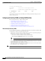
Setting the Default Power Allocation
The set inlinepower defaultallocation command is global and only affects Cisco IP phones. The inline
power threshold notification generates a syslog message when the inline power usage exceeds the specified
threshold. To set the default power allocation, perform this task in privileged mode (the default allocation
value is 15400 milliwatts):
Caution
Note
The set inlinepower defaultallocation command can be harmful when there is not enough power in the
system to bring up all connected inline power devices. If you set a small value for the power allocation,
all connected inline power devices initially will be powered up. However, after receiving CDP messages,
the system will learn that devices are consuming more power and deny power to some of the ports.
Setting a small value might also result in the overdrawing of power for some time with unanticipated
results, such as hardware failures and unexpected resets.
7000 milliwatts is the maximum power supported for these modules: WS-X6348-RJ21V,
WS-X6348-RJ-45V, WS-X6148-RJ-45V, and WS-X6148-RJ21V.
Task
Command
Set the default power allocation.
set inlinepower defaultallocation value
Catalyst 6500 Series Switch Software Configuration Guide—Release 8.7
OL-8978-02
55-17
Chapter 55
Configuring a VoIP Network
Configuring VoIP on a Switch
This example shows how to set the default power allocation:
Console> (enable) set inlinepower defaultallocation 9500
Default inline power allocation set to 9500 mWatt per applicable port.
Console> (enable)
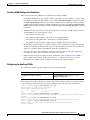
Setting the Inline Power Notification Threshold for a Module
Use the set inlinepower notify-threshold command to set a threshold for inline power usage. The threshold
is a percentage from 1 through 99, with 99 percent being the default. When the threshold is passed, a syslog
and trap (if configured) are generated.
To set the inline power notification threshold for a module, perform this task in privileged mode:
Task
Command
Set the inline power notification threshold for a
module.
set inlinepower notify-threshold {percentage
value} module {mod_num}
This example shows how to set the inline power notification threshold to 50 for module 4:
Console> (enable) set inlinepower notify-threshold 50 mod 4
Module 4 inlinepower notify-threshold is set to 50%.
Console> (enable)
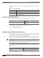
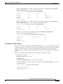
Displaying the Power Status for Modules and Individual Ports
To display the power status for the modules and individual ports, perform this task in normal mode:
Task
Command
Display the power status for the modules and
individual ports.
show port inlinepower [mod[/port]] [detail]
This example shows how to display the power status for the modules and individual ports:
Console> show port inlinepower 6/1
Configured Default Inline Power allocation per port: 15.400 Watts (0.36
Amps @42V)
Total inline power drawn by module 4: 33.934 Watts ( 0.807 Amps @42V)
Port
InlinePowered
PowerAllocated
Device
IEEE class
From PS
To PD
Admin Oper
mWatts
mWatts
----- ------ ------ ------------- ---------- ---------6/1 auto
on
7079
6300
cisco
none
Port
MaximumPower
mWatts
----- -----------6/1 15400
ActualConsumption
mWatts
----------------6300
Console>
Catalyst 6500 Series Switch Software Configuration Guide—Release 8.7
55-18
OL-8978-02
Chapter 55
Configuring a VoIP Network
Configuring VoIP on a Switch
This example shows how to display the detailed power status for the modules and individual ports:
Console> show port inlinepower 4/1 detail
Configured Default Inline Power allocation per port: 15.400 Watts (0.36
Amps @42V)
Total inline power drawn by module 4: 33.934 Watts ( 0.807 Amps @42V)
Port
InlinePowered
PowerAllocated Device
IEEE class DiscoverMode
From PS To PD
Admin Oper
Detected mWatts mWatts
----- ------ ------ -------- ------- ------- ---------- ---------- -----------4/1 auto
on
yes
7079
6300
cisco
none
cisco
Port
MaximumPower
mWatts
----- -----------4/1 15400
Console>
ActualConsumption
mWatts
----------------6300
absentCounter
OverCurrent
------------0
----------0
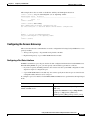
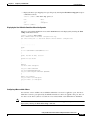
Displaying the Switch Power Environment for Modules
To display the switch power environment for the modules, perform this task in privileged mode:
Task
Command
Display the switch power environment for the
modules.
show environment power [mod]
This example shows how to display the switch power environment for the modules:
Console> (enable) show environment power 2
Feature not supported on module 2.
Console> (enable)
Console> (enable) show environment power
PS1 Capacity:1153.32 Watts (27.46 Amps @42V)
PS2 Capacity:none
PS Configuration :PS1 and PS2 in Redundant Configuration.
Total Power Available:1153.32 Watts (27.46 Amps @42V)
Total Power Available for Line Card Usage:1153.32 Watts (27.46 Amps @42V)
Total Power Drawn From the System:683.76 Watts (16.28 Amps @42V)
Total Inline Power Drawn From the System: 57.54 Watts ( 1.37 Amps @42V)
Remaining Power in the System:469.56 Watts (11.18 Amps @42V)
Configured Default Inline Power allocation per port:15.400 Watts (0.36 Amps
@42V)
Slot power Requirement/Usage :
Slot Card Type
PowerRequested
Watts
A @42V
---- ------------------- ------- -----1
WS-X6K-SUP2-2GE
128.52
3.06
2
0.00
0.00
3
WS-X6548-RJ-45
123.06
2.93
4
WS-X6148-RJ45V
100.38
2.39
6
WS-X6148-GE-TX
145.74
3.47
PowerAllocated
Watts
A @42V
------- -----128.52
3.06
128.52
3.06
123.06
2.93
100.38
2.39
145.74
3.47
CardStatus
---------ok
none
ok
ok
ok
Catalyst 6500 Series Switch Software Configuration Guide—Release 8.7
OL-8978-02
55-19
Chapter 55
Configuring a VoIP Network
Configuring VoIP on a Switch
Slot Inline Power Requirement/Usage :
Slot CardType
Supported
Total Allocated
Max H/W Supported
To Module (Watts) Per Module (Watts)
---- ------------------- ----------------- -----------------3
WS-X6548-RJ-45
31.08
315.84
6
WS-X6148-GE-TX
26.46
315.84
Console> (enable)
Max H/W
Per Port (Watts)
---------------15.400
7.000
A partial-deny status indicates that some module ports are inline powered but not all the ports on the
module are inline powered.
Configuring the Auxiliary VLANs on Catalyst LAN Switches
These sections describe how to configure auxiliary VLANs:
•
Understanding the Auxiliary VLANs, page 55-20
•
Auxiliary VLAN Configuration Guidelines, page 55-21
•
Configuring the Auxiliary VLANs, page 55-21
•
Verifying the Auxiliary VLAN Configuration, page 55-22
•
Disabling the Auxiliary VLANs Until an IP Phone is Detected, page 55-22
Understanding the Auxiliary VLANs
You can configure the switch ports to send CDP packets that instruct an attached Cisco IP Phone 7960
to transmit the voice traffic to the switch in these frame types:
•
802.1Q frames carrying the auxiliary VLAN ID and Layer 2 CoS set to 5 (the switch port drops all
802.1Q frames except those carrying the auxiliary VLAN ID).
– Reset the Cisco IP Phone 7960 if the auxiliary VLAN ID changes.
– Enter the set port auxiliaryvlan mod[/port] aux_vlan_id command.
Note
Note
We recommend that you use 802.1Q frames and a separate VLAN.
•
802.1p frames, which are 802.1Q frames carrying VLAN ID 0 and Layer 2 CoS set to 5 (enter the
set port auxiliaryvlan mod[/port] dot1p command).
•
802.3 frames, which are untagged and carry no VLAN ID and no Layer 2 CoS value (enter the set
port auxiliaryvlan mod[/port] untagged command).
The Cisco IP Phone 7960 always sets the Layer 3 IP precedence to 5 in the voice traffic.
Catalyst 6500 Series Switch Software Configuration Guide—Release 8.7
55-20
OL-8978-02
Chapter 55
Configuring a VoIP Network
Configuring VoIP on a Switch
Auxiliary VLAN Configuration Guidelines
This section describes the guidelines for configuring the auxiliary VLANs:
•
An auxiliary VLAN port is operationally a trunk, even though it is not treated like a “normal” trunk
port. When an auxiliary VLAN is added to a port and the set dot1q-all-tagged command is enabled,
the set dot1q-all-tagged command tags the native VLAN on the port where the auxiliary VLAN is
configured. A port with an auxiliary VLAN configured is not viewed as an 802.1Q trunk in the show
trunk command output, but the port acts like an 802.1Q trunk if the set dot1q-all-tagged command
is enabled.
•
The IP phone and a device that is attached to the phone are in the same VLAN and must be in the
same IP subnet if one of the following occurs:
– They use the same frame type.
– The phone uses 802.1p frames, and the device uses untagged frames.
– The phone uses untagged frames, and the device uses 802.1p frames.
– The phone uses 802.1Q frames, and the auxiliary VLAN equals the native VLAN.
•
The IP phone and a device that is attached to the phone cannot communicate if they are in the same
VLAN and subnet but use different frame types, because the traffic between the devices in the same
subnet is not routed (routing would eliminate the frame type difference).
•
You cannot use the switch commands to configure a frame type that is used by the traffic that is
received from a device that is attached to the phone’s access port.
•
With software release 6.2(1) and later releases, the dynamic ports can belong to two VLANs—a
native VLAN and an auxiliary VLAN. See Chapter 19, “Configuring Dynamic Port VLAN
Membership with VMPS,” for the configuration details for the auxiliary VLANs.
Configuring the Auxiliary VLANs
To configure the auxiliary VLANs, perform this task in privileged mode:
Task
Command
Configure the auxiliary VLANs.
set port auxiliaryvlan mod[/ports] {vlan |
untagged | dot1p | none}
This example shows how to add the voice ports to the auxiliary VLANs, specify an encapsulation type,
or specify that the VLAN will not send or receive CDP messages with voice-related information:
Console> (enable) set port auxiliaryvlan 2/1-3 222
Auxiliaryvlan 222 configuration successful.
AuxiliaryVlan AuxVlanStatus Mod/Ports
------------- ------------- ------------------------222
active
1/2,2/1-3
Console> (enable) set port auxiliaryvlan 5/7 untagged
Port 5/7 allows the connected device send and receive untagged packets and without 802.1p
priority.
Console> (enable) set port auxiliaryvlan 5/9 dot1p
Port 5/9 allows the connected device send and receive packets with 802.1p priority.
Console> (enable) set port auxiliaryvlan 5/12 none
Port 5/12 will not allow sending CDP packets with Voice VLAN information.
Console> (enable)
Catalyst 6500 Series Switch Software Configuration Guide—Release 8.7
OL-8978-02
55-21
Chapter 55
Configuring a VoIP Network
Configuring VoIP on a Switch
The default setting is none. Table 55-6 lists the set port auxiliaryvlan command keywords and their
descriptions.
Table 55-6
Keyword Descriptions
Keyword
Action
dot1p
Specify that the phone sends the packets with 802.1p priority 5.
untagged
Specify that the phone sends the untagged packets.
none
Specify that the switch does not send any auxiliary VLAN information in the
CDP packets from that port.
Verifying the Auxiliary VLAN Configuration
To verify the auxiliary VLAN configuration status, perform this task in privileged mode:
Task
Command
Verify the auxiliary VLAN configuration status.
show port auxiliaryvlan {vlan | untagged |
dot1p | none}
This example shows how to verify the auxiliary VLAN configuration status:
Console> show
AuxiliaryVlan
------------222
Console>
port auxiliaryvlan 123
AuxVlanStatus Mod/Ports
------------- ------------------------active
1/2,2/1-3
Disabling the Auxiliary VLANs Until an IP Phone is Detected
With software release 8.3(1) and later releases, this feature provides security for the auxiliary VLANs
by ensuring that the auxiliary VLAN is not enabled until an IP phone is detected. As soon the switch
detects the presence of an IP phone, the auxiliary VLAN is enabled.
The presence of an IP phone is determined through the CDP packet exchange between the switch and
the phone. This detection method is used for both the inline-powered and wall-powered IP phones.
Note
If the auxiliary VLAN ID equals the port-VLAN ID or when the auxiliary VLAN ID is configured as none,
dot1p, or untagged, this feature cannot be applied to the port. If any command entry results in the auxiliary
VLAN ID equaling the port-VLAN ID, the feature is disabled and the following warning message is
displayed: “cdpverify feature on port <mod>/<port> is disabled.”
To enable or disable the auxiliary VLAN IP phone detection, perform this task in privileged mode (the
default is disabled):
Task
Command
Enable or disable the auxiliary VLAN IP phone set port auxiliaryvlan mod[/port] {vlan | untagged
detection.
| dot1p | none} [cdpverify {enable | disable}]
Catalyst 6500 Series Switch Software Configuration Guide—Release 8.7
55-22
OL-8978-02
Chapter 55
Configuring a VoIP Network
Configuring VoIP on a Switch
This example shows how to enable or disable the auxiliary VLAN IP phone detection:
Console> (enable) set port auxiliaryvlan 3/1 50 cdpverify enable
AuxiliaryVlan Status
Mod/Ports
------------- -------- -----------------------------------------------------50
active
3/1
Console> (enable)
Console> (enable) show config
This command shows non-default configurations only.
Use 'show config all' to show both default and non-default configurations.
.
.
.
!
#module 3 : 48-port 10/100BaseTX Ethernet
set port auxiliaryvlan 3/1 50 cdpverify enable
!
Console> (enable)
Configuring the Access Gateways
This section describes the commands that are used to configure the following Catalyst 6500 series access
gateway modules:
•
Analog station gateway—24-port FXS analog interface module
•
Digital trunk gateway—8-port T1/E1 PSTN interface module
Configuring a Port Voice Interface
If DHCP is enabled for a port, the port obtains all other configuration information from the TFTP server.
When disabling DHCP on a port, you must specify some mandatory parameters as follows:
•
If you do not specify the DNS parameters, the software uses the system DNS configuration on the
supervisor engine to configure the port.
•
8-port T1/E1 PSTN interface module only: You cannot specify more than one port at a time because
a unique IP address must be set for each port.
To configure a port voice interface for the DHCP, TFTP, and DNS servers, perform this task in privileged
mode:
Task
Command
Configure a port voice interface for the DHCP,
TFTP, and DNS servers.
set port voice interface mod/port dhcp enable
[vlan vlan]
set port voice interface mod/port dhcp disable
{ipaddrspec} {tftp ipaddr} [vlan vlan]
[gateway ipaddr] [dns [ipaddr] [domain_name]]
Catalyst 6500 Series Switch Software Configuration Guide—Release 8.7
OL-8978-02
55-23
Chapter 55
Configuring a VoIP Network
Configuring VoIP on a Switch
These examples show how to configure the port voice interface for the DHCP, TFTP, and DNS servers:
Console> (enable) set port voice interface 7/1 dhcp enable
Port 7/1 DHCP enabled.
Console> (enable) set port voice interface 7/3 dhcp disable 171.68.111.41/24 tftp
173.32.43.11 dns 172.20.34.204 cisco.com
Port 7/3 dhcp disabled.
System DNS configurations applied.
Console> (enable) set port voice interface 7/4-6 dhcp enable vlan 3
Vlan 3 configuration successful
Ports 7/4-6 DHCP enabled.
Console> (enable)
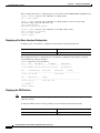
Displaying a Port Voice Interface Configuration
To display a port voice interface configuration, perform this task in privileged mode:
Task
Command
Display a port voice interface configuration.
show port voice interface [mod[/port]]
This example shows how to display the port voice interface configuration (this display is from the
24-port FXS analog interface module):
Console>
Port
-------5/1-24
show port voice interface
DHCP
MAC-Address
------- ----------------disable 00-10-7b-00-13-ea
5
IP-Address
Subnet-Mask
--------------- --------------10.6.15.158
255.255.255.0
Port
Call-Manager(s)
DHCP-Server
TFTP-Server
Gateway
-------- ----------------- --------------- --------------- --------------5/1-24 10.6.15.155
10.6.15.155
Port
DNS-Server(s)
Domain
-------- ----------------- ------------------------------------------------5/1-24 12.2.2.1*
cisco.cisco.com
7.7.7.7
(*): Primary
Console> (enable)
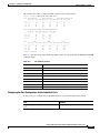
Displaying the FDL Statistics
Note
Facilities Data Link (FDL) is a link management protocol that is used to diagnose the problems and
gather the statistics.
To display the FDL statistics for the specified ports, perform this task in privileged mode:
Task
Command
Display the FDL statistics for the specified ports. show port voice fdl [mod[/port]]
Catalyst 6500 Series Switch Software Configuration Guide—Release 8.7
55-24
OL-8978-02
Chapter 55
Configuring a VoIP Network
Configuring VoIP on a Switch
This example shows how to display the FDL statistics for the specified ports:
Console> (enable) show port voice fdl 7/1-3
Port ErrorEvents
ErroredSecond
SeverlyErroredSecond
Last 15' Last 24h Last 15' Last 24h Last 15' Last 24h
----- -------- -------- -------- -------- -------- ----------7/1 17
18
19
20
21
22
7/2 17
18
19
20
21
22
7/3 17
18
19
20
21
22
Port
FailedSignalState
Last 15' Last 24h
----- -------- -------7/1 37
38
7/2 37
38
7/3 37
38
FailedSignalSecond
Last 15' Last 24h
-------- --------39
40
39
40
39
40
Port
BES
Last 15' Last 24h
-------- -------49
50
49
50
49
50
LES
Last 15' Last 24h
----- -------- -------7/1 41
48
7/2 41
48
7/3 41
48
Console> (enable)
LCV
Last 15' Last 24h
-------- -------53
54
53
54
53
54
Table 55-7 describes the possible fields (depending on the port type queried) in the show port voice fdl
command output.
Table 55-7
FDL Field Descriptions
Field
Description
ErrorEvents
Count of errored events.
ErroredSecond
Count of errored seconds.
SeverelyErroredSecond
Count of severely errored seconds.
FailedSignalState
Count of failed signal state errors.
FailedSignalSecond
Count of errored events.
LES
Line errored seconds detected.
BES
Bursty errored seconds detected.
LCV
Line code violation seconds detected.
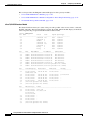
Displaying the Port Configuration for the Individual Ports
To display the port configuration for the individual ports, perform this task in normal mode:
Task
Command
Display the port configuration for the individual
ports.
show port [mod[/port]]
Catalyst 6500 Series Switch Software Configuration Guide—Release 8.7
OL-8978-02
55-25
Chapter 55
Configuring a VoIP Network
Configuring VoIP on a Switch
This section provides the show port command displays for these gateway modules:
•
8-Port T1/E1 PSTN Interface Module, page 55-26
•
8-Port T1/E1 PSTN Interface Module Configured for Trancoding/Conferencing, page 55-27
•
24-Port FXS Analog Interface Module, page 55-28
8-Port T1/E1 PSTN Interface Module
The Status field shows the Layer 2 status of the ports. The possible values are notconnect, connected,
disabled, and faulty. The following display is for the T1 module. The E1 module display would be the
same except that the port speed for the E1 module would be 2.048.
Console> show port 7
Port Name
----- -----------------7/1
7/2
7/3
7/4
7/5
7/6
7/7
7/8
Port
-------7/1
7/2
7/3
7/4
7/5
7/6
7/7
7/8
DHCP
------enable
enable
enable
enable
enable
enable
enable
enable
Status
---------connected
connected
disable
connected
connected
connected
faulty
faulty
MAC-Address
----------------00-10-7b-00-0a-58
00-10-7b-00-0a-59
00-10-7b-00-0a-5a
00-10-7b-00-0a-5b
00-10-7b-00-0a-5c
00-10-7b-00-0a-5d
00-10-7b-00-0a-5e
00-10-7b-00-0a-5f
Vlan
---------123
2
1
11
123
1
2
2
7/3
7/4
7/5
7/6
7/7
7/8
Speed
----1.544
1.544
1.544
1.544
1.544
1.544
1.544
1.544
Type
-----------T1
T1
T1
T1
T1
T1
T1
T1
IP-Address
Subnet-Mask
--------------- --------------172.20.34.68
255.255.255.0
172.20.34.70
255.255.255.0
172.20.34.64
255.255.255.0
172.20.34.66
255.255.255.0
172.20.34.59
255.255.255.0
172.20.34.67
255.255.255.0
(Port host processor not online)
(Port host processor not online)
Port
Call-Manager(s)
DHCP-Server
-------- ----------------- --------------7/1
172.20.34.207*
172.20.34.207
callm.cisco.com
7/2
172.20.34.207
172.20.34.207
7/3
172.20.34.207
172.20.34.207
7/4
172.20.34.207
172.20.34.207
7/5
172.20.34.207
172.20.34.207
7/6
172.20.34.207
172.20.34.207
7/7
(Port host processor not online)
7/8
(Port host processor not online)
Port
-------7/1
7/2
Duplex
-----full
full
full
full
full
full
full
full
TFTP-Sever
Gateway
--------------- --------------172.20.34.207
172.20.34.207
172.20.34.207
172.20.34.207
172.20.34.207
172.20.34.207
172.20.34.20
-
DNS-Server(s)
Domain
--------------- ------------------------------------------------172.20.34.207
cisco.com
172.20.34.207* int.cisco.com
171.69.45.34
172.78.111.132
172.20.34.207
172.20.34.207
172.20.34.207
172.20.34.207
(Port host processor not online)
(Port host processor not online)
Catalyst 6500 Series Switch Software Configuration Guide—Release 8.7
55-26
OL-8978-02
Chapter 55
Configuring a VoIP Network
Configuring VoIP on a Switch
Port
-------7/1
7/2
7/3
7/4
7/5
7/6
7/7
7/8
Port
----7/1
7/2
7/3
7/4
7/5
7/6
7/7
7/8
CallManagerState DSP-Type
---------------- -------registered
C549
registered
C549
registered
C549
registered
C549
registered
C549
notregistered
C549
(Port host processor not online)
(Port host processor not online)
NoiseRegen
---------disabled
disabled
disabled
disabled
enabled
disabled
(Port host
(Port host
NonLinearProcessing
------------------disabled
disabled
disabled
disabled
disabled
enabled
processor not online)
processor not online)
(*): Primary
Console>
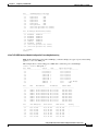
8-Port T1/E1 PSTN Interface Module Configured for Trancoding/Conferencing
MTP (media termination point) and Conf Bridge (conference bridge) are types of ports. Transcoding
applies to a call on an MTP port.
This example shows a transcoding port as MTP and a conference port as Conf Bridge:
Console> (enable) show port 7
Port Name
Status
----- ------------------ ---------7/1
notconnect
7/2
notconnect
7/3
connected
7/4
connected
7/5
connected
7/6
connected
7/7
enabled
7/8
enabled
Port
-------7/1
7/2
7/3
7/4
7/5
7/6
7/7
7/8
DHCP
------enable
enable
enable
enable
enable
enable
enable
enable
MAC-Address
----------------00-10-7b-00-12-08
00-10-7b-00-12-09
00-10-7b-00-12-0a
00-10-7b-00-12-0b
00-10-7b-00-12-0c
00-10-7b-00-12-0d
00-10-7b-00-12-0e
00-10-7b-00-12-0f
Port
-------7/1
7/2
7/3
7/4
7/5
7/6
Call-Manager(s)
----------------10.6.15.155
10.6.15.155
10.6.15.155
10.6.15.155
10.6.15.155
10.6.15.155
Vlan
Duplex Speed Type
---------- ------ ----- -----------1
full 1.544 T1
1
full 1.544 T1
1
full 1.544 T1
1
full 1.544 T1
1
full 1.544 T1
1
full 1.544 T1
1
full
- Conf Bridge
1
full
- MTP
IP-Address
--------------10.6.15.165
10.6.15.166
10.6.15.167
10.6.15.168
10.6.15.169
10.6.15.170
10.6.15.171
10.6.15.172
DHCP-Server
--------------10.6.15.155
10.6.15.155
10.6.15.155
10.6.15.155
10.6.15.155
10.6.15.155
Subnet-Mask
--------------255.255.255.0
255.255.255.0
255.255.255.0
255.255.255.0
255.255.255.0
255.255.255.0
255.255.255.0
255.255.255.0
TFTP-Server
--------------10.6.15.155
10.6.15.155
10.6.15.155
10.6.15.155
10.6.15.155
10.6.15.155
Gateway
---------------
Catalyst 6500 Series Switch Software Configuration Guide—Release 8.7
OL-8978-02
55-27
Chapter 55
Configuring a VoIP Network
Configuring VoIP on a Switch
7/7
7/8
10.6.15.155
10.6.15.155
10.6.15.155
10.6.15.155
10.6.15.155
10.6.15.155
-
Port
-------7/1
7/2
7/3
7/4
7/5
7/6
7/7
7/8
DNS-Server(s)
-----------------
Domain
-------------------------------------------------
Port
-------7/1
7/2
7/3
7/4
7/5
7/6
7/7
7/8
CallManagerState
---------------registered
registered
registered
registered
registered
registered
registered
registered
DSP-Type
-------C549
C549
C549
C549
C549
C549
C549
C549
Port NoiseRegen NonLinearProcessing
----- ---------- ------------------7/1 enabled
enabled
7/2 enabled
enabled
7/3 enabled
enabled
7/4 enabled
enabled
7/5 enabled
enabled
7/6 enabled
enabled
7/7 disabled
disabled
7/8 disabled
disabled
Console> (enable)
24-Port FXS Analog Interface Module
This example shows that all ports should have a Type field of FXS, and all ports in the same module
should belong to one VLAN:
Console> (enable) show port 3
Port Name
Status
----- ------------------ ---------3/1
onhook
3/2
onhook
3/3
onhook
3/4
onhook
3/5
onhook
3/6
onhook
3/7
onhook
3/8
offhook
3/9
offhook
3/10
onhook
3/11
onhook
3/12
onhook
3/13
onhook
3/14
onhook
3/15
onhook
3/16
onhook
3/17
onhook
3/18
onhook
Vlan
Duplex Speed Type
---------- ------ ----- -----------1
full
64k FXS
1
full
64k FXS
1
full
64k FXS
1
full
64k FXS
1
full
64k FXS
1
full
64k FXS
1
full
64k FXS
1
full
64k FXS
1
full
64k FXS
1
full
64k FXS
1
full
64k FXS
1
full
64k FXS
1
full
64k FXS
1
full
64k FXS
1
full
64k FXS
1
full
64k FXS
1
full
64k FXS
1
full
64k FXS
Catalyst 6500 Series Switch Software Configuration Guide—Release 8.7
55-28
OL-8978-02
Chapter 55
Configuring a VoIP Network
Configuring VoIP on a Switch
3/19
3/20
3/21
3/22
3/23
3/24
onhook
onhook
onhook
onhook
onhook
onhook
1
1
1
1
1
1
full
full
full
full
full
full
64k
64k
64k
64k
64k
64k
FXS
FXS
FXS
FXS
FXS
FXS
Port
DHCP
MAC-Address
IP-Address
Subnet-Mask
-------- ------- ----------------- --------------- --------------3/1-24 enable 00-10-7b-00-13-e4 172.20.34.50
255.255.255.0
Port
Call-Manager(s)
DHCP-Server
TFTP-Sever
Gateway
-------- ----------------- --------------- --------------- --------------3/1-24 172.20.34.207
172.20.34.207
172.20.34.207
Port
DNS-Server(s)
Domain
-------- ----------------- ------------------------------------------------3/1-24 172.20.34.207*
cisco.com
172.34.23.111
Port
CallManagerState DSP-Type
-------- ---------------- -------3/1-24 registered
C549
Port
ToneLocal
Impedance InputGain(dB) OutputAtten(dB)
-------- ------------- --------- ------------- --------------3/1-24 northamerica 0
0
0
Port
RingFreq
(Hz)
-------- -------3/1-24 20
(*): Primary
Console> (enable)
Timing
Digit(ms)
--------100
Timing
InterDigit(ms)
-------------100
Timing
Pulse(ms)
--------0
Timing
PulseDigit(ms)
-------------0
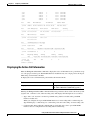
Displaying the Active Call Information
Enter the show port voice active command to display the active call information on a port. There are up
to 8 calls per port for the 8-port T1/E1 PSTN interface module but only one call per port for the 24-port
FXS analog station interface module.
To display the active call information, perform this task in normal mode:
Task
Command
Display the active call information.
show port voice active [mod/port]
[all | call | conference | transcode] [ipaddr]
Entering the show port voice active command without any parameters shows all the calls in the system
(regular calls, conference calls, and transcoding calls). The display field descriptions are as follows:
•
Type—The “call” notation is for the 24-port FXS analog interface module and 8-port PSTN
interface module calls.
When you configure the 8-port T1/E1 PSTN interfaces for transcoding and/or conferencing, the
Type field displays “conferencing” for conferencing calls and “transcoding” for transcoding calls.
•
Conference-ID, Transcoding-ID, and Party-ID are applicable only to the 8-port T1/E1 PSTN
interfaces that are configured for transcoding and/or conferencing.
Catalyst 6500 Series Switch Software Configuration Guide—Release 8.7
OL-8978-02
55-29
Chapter 55
Configuring a VoIP Network
Configuring VoIP on a Switch
This example shows all the active calls in the system:
Console> show port voice active
Port Type
Total Conference-ID/
Transcoding-ID
----- ------------ ----- -------------3/1 call
1
3/2 call
1
4/5 call
3
-
3/8
conferencing 2
1
2
3/2
3/8
call
transcoding
1
1
1
Party-ID IP-Address
--------
1
2
3
5
1
3
6
1
2
--------------199.22.25.254
172.225.25.54
165.34.234.111
172.32.34.12
198.96.23.111
255.255.255.241
173.23.13.42
198.97.123.98
182.34.54.26
199.22.25.25
182.34.54.2
121.43.23.43
172.225.25.54
255.255.255.241
183.32.43.3
This example shows how to display the detailed call information for a port (specifying the module only,
this example shows the detailed call information for all the ports on the module):
Console> show port voice active 3/2
Port 3/2:
Channel #1:
Remote IP address
Remote UDP port
Call state
Codec Type
Coder Type Rate
Tx duration
Voice Tx duration
ACOM Level Current
ERL Level
Fax Transmit Duration
Hi Water Playout Delay
Logical If index
Low water playout delay
Receive delay
Receive bytes
Receive packets
Transmit bytes
Transmit packets
Channel #2:
Remote IP address
Remote UDP port
Call state
Codec Type
Coder Type Rate
Tx duration
Voice Tx duration
ACOM Level Current
ERL Level
Fax Transmit Duration
Hi Water Playout Delay
Logical If index
Low water playout delay
Receive delay
:
:
:
:
:
:
:
:
:
:
:
:
:
:
:
:
:
:
165.34.234.111
124
Ringing
G.711
35243
438543 sec
34534 sec
123213
123 dB
332433
23004 ms
4
234 ms
23423 ms
2342342332423
23423423402384
23472377
94540
:
:
:
:
:
:
:
:
:
:
:
:
:
:
165.34.234.112
125
Ringing
G.711
35243
438543 sec
34534 sec
123213
123 dB
332433
23004 ms
4
234 ms
23423 ms
Catalyst 6500 Series Switch Software Configuration Guide—Release 8.7
55-30
OL-8978-02
Chapter 55
Configuring a VoIP Network
Configuring VoIP on a Switch
Receive bytes
Receive packets
Transmit bytes
Transmit packets
Channel #3:
.
(display text omitted)
.
Console>
:
:
:
:
2342342332423
23423423402384
23472377
94540
This example shows how to display a specific call at a specified IP address:
Console> show port voice active 3/2 171.69.67.91
Remote IP address
: 171.69.67.91
Remote UDP port
: 125
Call state
: Ringing
Codec Type
: G.711
Coder Type Rate
: 35243
Tx duration
: 438543 sec
Voice Tx duration
: 34534 sec
ACOM Level Current
: 123213
ERL Level
: 123 dB
Fax Transmit Duration
: 332433
Hi Water Playout Delay
: 23004 ms
Logical If index
: 4
Low water playout delay
: 234 ms
Receive delay
: 23423 ms
Receive bytes
: 2342342332423
Receive packets
: 23423423402384
Transmit bytes
: 23472377
Transmit packets
: 94540
Console>
Configuring QoS in the Cisco IP Phone 7960
These sections describe QoS in the Cisco IP Phone 7960:
•
Understanding How QoS Works in the Cisco IP Phone 7960, page 55-31
•
Configuring QoS in the Cisco IP Phone 7960, page 55-32
Note
For information on using automatic QoS, see Chapter 52, “Using Automatic QoS.”
Note
For information on using automatic voice configuration, see the “Using SmartPorts” section on
page 55-38.
Understanding How QoS Works in the Cisco IP Phone 7960
Note
The Cisco IP Phone 7960 always sets the Layer 3 IP precedence and Layer 2 CoS to 5 in the voice traffic
that is generated by the phone. The Layer 3 IP precedence and Layer 2 CoS values in the voice traffic
that is generated by the phone are not configurable.
Catalyst 6500 Series Switch Software Configuration Guide—Release 8.7
OL-8978-02
55-31
Chapter 55
Configuring a VoIP Network
Configuring VoIP on a Switch
You can configure the Cisco IP Phone 7960 access port (see Figure 55-5) to either trusted or untrusted
mode.
In untrusted mode, all the traffic in the 802.1Q or 802.1p frames that are received through the access port
is marked with a configured Layer 2 CoS value. The default Layer 2 CoS value is 0. The untrusted mode
is the default when the phone is connected to a Cisco LAN switch.
In trusted mode, all the traffic that is received through the access port passes through the phone switch
unchanged. The trusted mode is the default when the phone is not connected to a Cisco LAN switch.
The traffic in the frame types other than 802.1Q or 802.1p passes through the phone switch unchanged,
regardless of the access port trust state.
Figure 55-5
Configuring QoS on the IP Phone Ports
Cisco IP Phone 7960
Phone
ASIC
Catalyst switch
Workstation/PC
P2
P1
3-port
switch
P3
Access
port
38204
10/100 module
Configuring QoS in the Cisco IP Phone 7960
These sections describe how to configure QoS in the Cisco IP Phone 7960:
•
Setting the Phone Access Port Trust Mode, page 55-32
•
Setting the Phone Access Port CoS Value, page 55-33
•
Verifying the Phone Access Port QoS Configuration, page 55-33
Setting the Phone Access Port Trust Mode
To set the phone access port trust mode, perform this task in privileged mode:
Task
Command
Set the phone access port trust mode.
set port qos mod/ports...trust-ext {trusted |
untrusted}
This example shows how to set the phone access port to the trusted mode:
Console> (enable) set port qos 3/7 trust-ext trusted
Port in the phone device connected to port 3/7 is configured to be trusted.
Console> (enable)
Catalyst 6500 Series Switch Software Configuration Guide—Release 8.7
55-32
OL-8978-02
Chapter 55
Configuring a VoIP Network
Configuring VoIP on a Switch
This example shows how to set the phone access port to the untrusted mode:
Console> (enable) set port qos 3/7 trust-ext untrusted
Port in the phone device connected to port 3/7 is configured to be untrusted.
Console> (enable)
Setting the Phone Access Port CoS Value
To set the phone access port CoS value, perform this task in privileged mode:
Task
Command
Set the phone access port CoS value.
set port qos mod/ports cos-ext cos_value
This example shows how to set the Layer 2 CoS value that is used by a phone access port in untrusted
mode:
Console> (enable) set port qos 2/1 cos-ext 3
Port 2/1 qos cos-ext set to 3.
Console> (enable)
Verifying the Phone Access Port QoS Configuration
To verify the phone access port QoS configuration, perform this task in normal mode:
Task
Command
Verify the phone access port QoS configuration.
show port qos [mod[/port]]
This example shows how to verify the phone access port QoS configuration:
Console> (enable) show port qos 3/4
<...Output Truncated...>
Port Ext-Trust Ext-Cos
----- --------- ------3/4 untrusted
0
<...Output Truncated...>
Configuring a Trusted Boundary to Ensure Port Security
This section describes the trusted boundary that is used to prevent security problems if users disconnect
their PCs from the networked Cisco IP Phones and plug them directly into the switch port to take advantage
of the QoS trust-cos switch port settings.
These sections describe the trusted boundary:
•
Supported Cisco IP Phones, page 55-34
•
QoS and Cisco IP Phone Configuration, page 55-34
•
QoS, Cisco IP Phone, and PC Configuration, page 55-34
•
Trusted Boundary Configuration Guidelines, page 55-35
•
Configuring a Trusted Boundary, page 55-36
Catalyst 6500 Series Switch Software Configuration Guide—Release 8.7
OL-8978-02
55-33
Chapter 55
Configuring a VoIP Network
Configuring VoIP on a Switch
Supported Cisco IP Phones
These Cisco IP phones are supported with the trusted boundary feature:
•
Cisco IP Phone 7910
•
Cisco IP Phone 7935
•
Cisco IP Phone 7940
•
Cisco IP Phone 7960
QoS and Cisco IP Phone Configuration
The Cisco IP Phones are directly attached to the Catalyst 6500 series switch ports. Typically, the traffic
that is coming from the phone and entering the switch is marked with a tag using the 802.1Q header. The
header contains the VLAN information and the class of service (CoS) 3-bit field. The CoS determines
the priority of the packet. For most Cisco IP Phone configurations, the traffic that comes from the phone
and enters the switch is trusted to ensure that the voice traffic is properly prioritized over other types of
traffic in the network. The port on the switch where the phone is attached is configured to trust-cos,
which means that the port trusts the CoS labeling of all packets arriving on that port.
QoS, Cisco IP Phone, and PC Configuration
A PC or workstation can be attached to the Cisco IP Phone. The phone has a built-in hub that mixes the
traffic coming from the PC, the phone, and the switch port. To distinguish the traffic that comes from the
PC from the traffic that comes from the phone, use the 3-bit CoS labels.
You need to configure the QoS features on the phone for proper labeling to occur. The QoS configuration
information is sent to the phone using CDP from the switch. The QoS configuration determines the trust
state of the phone and the classification information (Ext-Cos). The phone supports two trust states:
•
Trusted
•
Untrusted and marked with a new COS value (Ext-Cos)
If the phone is in trusted mode, all the labels that are produced by the PC are sent directly through the
phone toward the switch, untouched. If the phone is in untrusted mode, all traffic coming from the PC is
marked with the Ext-Cos value before it is sent to the switch.
For most setups, the PC or workstation that is attached to the phone is unable to tag its packets. In these
cases, all the traffic that comes from the PC and enters the switch through the phone, is marked with the
“default ext-cos” that is configured on the phone.
In some cases, the PC can tag its own packets. A PC running Windows 2000 can be configured to send
the 802.1Q frames of any priority. To solve this problem, the phones should be configured to be
untrusted, which marks all the traffic coming from the PC to the appropriate priority.
The trusted boundary prevents the users from taking advantage of the trust-cos setting on the switch by
disconnecting their phone from the network and plugging their PC directly into the switch port. It uses
CDP to detect the phone’s presence on a port. If the phone leaves the port, the feature automatically
configures the port to be untrusted, which solves the security issue.
The trusted boundary is implemented using a configuration command to create a new type of trust. The
command allows you to configure the port trust based on the presence of a given device on a port. For
the Cisco IP Phones, you configure the trust as “trust-device ciscoipphone.”
Catalyst 6500 Series Switch Software Configuration Guide—Release 8.7
55-34
OL-8978-02
Chapter 55
Configuring a VoIP Network
Configuring VoIP on a Switch
Trusted Boundary Configuration Guidelines
This section describes the guidelines for configuring the trusted boundary:
•
Common Open Policy Service (COPS) considerations
COPS directly affects how the QoS parameters are applied. A port may have either a local policy or
a COPS policy. This setting specifies whether the port should get its QoS configuration information
from the local configuration or through a COPS server. If COPS is enabled on a port and is also
globally enabled, the policy that is specified by the COPS server applies. If COPS is disabled and/or
the run-time policy is local, the local configuration QoS policy applies. The extended trust boundary
feature overrides the “local” policy on a port.
•
QoS configuration support
All the QoS port trust configuration settings are supported (trust-cos, trust-ipprec, trust-dscp), but
you should use trust-cos for the Cisco IP Phone networks.
•
System log messaging
New QoS syslogs were added for the trusted boundary to notify you of the changes to a port’s trust state
and to warn of improper configuration. To see these syslogs, set the QoS logging level to 5 (set logging
level qos 5). The default is 3. Refer to the Catalyst 6500 Series System Message Guide for the
descriptions of the syslogs.
•
Final run-time port trust value
The final run-time port trust on any port is dependent on the following:
– Trusted boundary configuration
– Phone’s presence on the port
– QoS configuration
– COPS configuration
To enable the trusted boundary, you must enable QoS and you must enable CDP globally and on the
port, running in version 2 mode. You must set COPS to local policy (the COPS default) or to disabled
(the COPS default). When ciscoipphone is configured as the trust-device on the port, the feature is
enabled and detects the presence of a Cisco IP Phone and sets the trust values.
See Figure 55-6 to determine the final trust value on a port.
Catalyst 6500 Series Switch Software Configuration Guide—Release 8.7
OL-8978-02
55-35
Chapter 55
Configuring a VoIP Network
Configuring VoIP on a Switch
Figure 55-6
QoS
Enabled
Determining the Final Trust Value of a Port
No
Yes
COPS
Enabled
No
Trust-Device
Type
Port set to default QoS disabled setttings.
Port
Policy
COPS
Port set to policy defined by COPS
server/role.
Local
None
Port set to QoS parameters as defined per
the configuration
ciscoipphone
CDP
Enabled on
Port
No
Yes
IP Phone
Persent on
Port
Yes
Port trust state set to untrusted, other QoS
parameters set per the configuration.
68899
No
Configuring a Trusted Boundary
These sections describe how to configure the trusted boundary feature:
•
Default Configuration, page 55-37
•
Specifying a Cisco IP Phone as the Trust Device, page 55-37
•
Verifying a Port’s Trust-Device State, page 55-37
Catalyst 6500 Series Switch Software Configuration Guide—Release 8.7
55-36
OL-8978-02
Chapter 55
Configuring a VoIP Network
Configuring VoIP on a Switch
Default Configuration
The default setting for all ports is trust-device none.
Specifying a Cisco IP Phone as the Trust Device
To specify a Cisco IP Phone as the trust device, perform this task in privileged mode:
Task
Command
Specify a Cisco IP Phone as the trust device.
set port qos mod/ports...trust-device
[ciscoipphone | none]
This example shows how to trust only Cisco IP phones on port 4/1:
Console> (enable) set port qos 4/1 trust-device ciscoipphone
Port 4/1 set to only trust device of type ciscoIPPhone.
Console> (enable)
This example shows how to disable the device trust on port 4/1:
Console> (enable) set port qos 4/1 trust-device none
Port 4/1 trust device feature disabled.
Console> (enable)
Verifying a Port’s Trust-Device State
To verify a port’s trust-device state, perform this task in normal mode:
Task
Command
Verify a port’s trust-device state.
show port qos [mod[/port]]
When the trusted boundary is active, the run-time trust state of the port changes depending on the
presence of the phone.
Note
The moment that the phone leaves the switch port, there is a slight convergence time for the port to
change to the untrusted state (a maximum time of 15 seconds).
This example shows how to verify the trust-device state and trust state on port 4/1:
Console> (enable) show port qos 4/1
<truncated ...>
Port
TxPort Type
RxPort Type
Trust Type
Trust Type
Def CoS Def CoS
config
runtime
config runtime
----- ------------ ------------ ------------ ------------- ------- ------4/1
1p3q1t
1p1q0t
trust-cos
trust-cos*
0
0
Port
Ext-Trust Ext-Cos Trust-Device
----- --------- ------- -----------4/1
untrusted
0 ciscoIPPhone
Catalyst 6500 Series Switch Software Configuration Guide—Release 8.7
OL-8978-02
55-37
Chapter 55
Configuring a VoIP Network
Using SmartPorts
(*)Runtime trust type set to untrusted.
Config:
Port ACL name
Type
----- -------------------------------- ---No ACL is mapped to port 4/1.
Runtime:
Port ACL name
Type
----- -------------------------------- ---No ACL is mapped to port 4/1.
Console> (enable)
Using SmartPorts
The SmartPorts feature consists of two macros that simplify voice configuration on the Catalyst 6500
series switches. The SmartPorts macros cover all the voice configuration tasks that are required for
implementing the recommended Architecture for Voice, Video, and Integrated Data (AVVID) settings
for a voice port.
SmartPorts focuses on the voice networks that are built using the Cisco IP Phone 79xx series and the
Cisco SoftPhone. With SmartPorts, you use the ciscoipphone or ciscosoftphone keywords to initiate the
macros that specify the type of voice parameters that you desire on a particular port.
SmartPorts is described in these sections:
•
Understanding SmartPorts Macros, page 55-38
•
SmartPorts—Cisco IP Phone, page 55-39
•
SmartPorts—Cisco Softphone, page 55-39
•
SmartPorts Guidelines and Restrictions, page 55-40
•
CLI Interface for SmartPorts, page 55-41
•
Detailed SmartPorts Statements, page 55-42
•
How to Use SmartPorts in Your Network, page 55-43
•
SmartPorts Enhancements in Software Release 8.4(1), page 55-44
•
Configuring User-Definable SmartPorts Macros, page 55-47
Understanding SmartPorts Macros
When you execute the SmartPorts macros on a port using the ciscoipphone or ciscosoftphone keywords,
these features are implemented:
•
The port is enabled.
•
The Layer 2 protocol is disabled for CDP, STP, and VTP.
•
The port membership is set to “static.”
•
The set port host command is executed on the port.
•
The specified data VLAN is associated with the port.
•
The global automatic QoS command is executed.
Catalyst 6500 Series Switch Software Configuration Guide—Release 8.7
55-38
OL-8978-02
Chapter 55
Configuring a VoIP Network
Using SmartPorts
When you execute the ciscoipphone keyword on a port, in addition to the previous features, these
features are also implemented:
•
The specified auxiliary VLAN is associated with the port.
•
The inline power is enabled.
•
CDP is enabled globally and on the port.
•
CDP is configured to version v2.
•
The port-based automatic QoS command for the Cisco IP phone is executed.
When you execute the ciscosoftphone keyword on a port, in addition to the previous features, these
features are also implemented:
•
The auxiliary VLAN for the port is set to “none.”
•
The port-based automatic QoS command for the Cisco SoftPhone is executed.
SmartPorts—Cisco IP Phone
In most configurations, the Cisco IP Phone 79xx is connected directly to the Catalyst switch port.
Optionally, you can attach a PC to the phone and use the phone as a hop to the switch.
Typically, the traffic that comes from the phone and enters the switch is marked with a tag using the
802.1Q/p header. The header contains the VLAN information and the CoS 3-bit field. The CoS
determines the priority of the packet. The switch uses the CoS field to distinguish the PC traffic from the
phone traffic. The switch can also use the DSCP field for the same purpose.
In most Cisco IP Phone 79xx configurations, the traffic that comes from the phone and enters the switch
is trusted. You set the port trust to trust-cos to properly prioritize the voice traffic over other types of
traffic in the network.
The Cisco IP Phone 79xx has a built-in switch that mixes the traffic that comes from the PC, the phone,
and the switch port. The Cisco IP Phone 79xx has the trust and classification capabilities that you need
to configure.
The ports that connect the IP phones need to have several features enabled or disabled. SmartPorts
ensures that the necessary features are enabled. Most of these features are implemented when you
execute the set port host command (such as disabling channels, enabling PortFast, and so on). A VLAN
and an auxiliary VLAN must be configured on the port for QoS to work. The inline power needs to be
enabled (if available), and CDP must be enabled for the trusted boundary feature to work. QoS
configuration is handled by the automatic QoS feature (see Chapter 52, “Using Automatic QoS”).
SmartPorts—Cisco Softphone
The Cisco SoftPhone is a software product that runs on a standard PC and emulates an IP phone. The
main difference between the Cisco SoftPhone and the Cisco IP Phone 79xx is that the Cisco SoftPhone
marks its voice traffic through a DSCP, while the Cisco IP Phone 79xx marks its traffic through a CoS.
The QoS settings on the switch accommodate this behavior by trusting the Layer 3 marking of the traffic
entering the port. All other behavior is similar to the Cisco IP Phone 79xx. Some features, such as CDP,
do not need to be enabled because the trusted boundary does not support Cisco SoftPhone.
Catalyst 6500 Series Switch Software Configuration Guide—Release 8.7
OL-8978-02
55-39
Chapter 55
Configuring a VoIP Network
Using SmartPorts
SmartPorts Guidelines and Restrictions
These sections provide the configuration guidelines and restrictions for SmartPorts:
•
Supported Phones, page 55-40
•
CDP Dependencies, page 55-40
•
EtherChannel Considerations, page 55-40
•
PFC/PFC2 Support, page 55-40
•
Module Support, page 55-40
Supported Phones
When you use SmartPorts with the ciscoipphone keyword, some of the QoS configuration requires
phone-specific configuration (trust-ext, ext-cos) which is supported only on the following phones: Cisco
IP Phone 7910, Cisco IP Phone 7940, Cisco IP Phone 7960, and Cisco IP Phone 7935. However, the
ciscoipphone keyword is not exclusive to these models only; any phone can benefit from all the other
QoS settings that are configured on the switch.
The Cisco SoftPhone is supported through the ciscoipsoftphone keyword.
CDP Dependencies
To configure the QoS settings and the trusted boundary on the Cisco IP Phone, you must enable CDP
version 2 or later on the port.
You need to enable CDP only for the ciscoipphone QoS configuration; CDP does not affect the other
components of the SmartPorts feature.
EtherChannel Considerations
The SmartPorts commands do not support channeling.
PFC/PFC2 Support
No PFC or PFC2 is required for the ciscoipphone keyword. A PFC or PFC2 is required for the
ciscosoftphone keyword.
Module Support
The ciscoipphone keyword is supported only on the 10/100 and 10/100/1000 Ethernet ports.
The ciscosoftphone keyword is supported on all Ethernet ports.
Catalyst 6500 Series Switch Software Configuration Guide—Release 8.7
55-40
OL-8978-02
Chapter 55
Configuring a VoIP Network
Using SmartPorts
CLI Interface for SmartPorts
These sections describe the CLI interface for SmartPorts:
•
Command Description, page 55-41
•
ciscoipphone Command Output, page 55-41
•
ciscosoftphone Command Output, page 55-42
Command Description
You must specify either the ciscoipphone or ciscosoftphone keywords and a data VLAN. Specifying an
auxiliary VLAN is optional for the ciscoipphone keyword. The RSPAN and private VLANs are not
supported. The command syntax for SmartPorts is as follows:
Console> (enable) set port macro
Usage: set port macro <mod/ports..> ciscoipphone vlan <vlan> [auxvlan <auxvlan>]
set port macro <mod/ports..> ciscosoftphone vlan <vlan>
Console> (enable)
Note
The set port macro mod/ports... ciscoipphone vlan vlan [auxvlan auxvlan] command enables the
“cdpverify” feature on the port.
ciscoipphone Command Output
When you enter the ciscoipphone keyword, the following displays (specifying the auxiliary VLAN is
optional):
Console> (enable) set port macro 3/1 ciscoipphone vlan 2 auxvlan 3
Port 3/1 enabled.
Layer 2 protocol tunneling disabled for CDP STP VTP on port(s) 3/1.
Port 3/1 vlan assignment set to static.
Spantree port fast start option set to default for ports 3/1.
Port(s) 3/1 channel mode set to off.
Warning: Connecting Layer 2 devices to a fast start port can cause
temporary spanning tree loops. Use with caution.
Spantree port 3/1 fast start enabled.
Dot1q tunnel feature disabled on port(s) 3/1.
Port(s) 3/1 trunk mode set to off.
VLAN Mod/Ports
---- ----------------------2
2/1
3/1
16/1
AuxiliaryVlan Status
Mod/Ports
------------- ------------------------------------------------------------3
inactive 3/1
Vlan 3 is not active.
Inline power for port 3/1 set to auto.
CDP enabled globally
CDP enabled on port 3/1.
CDP version set to v2
........
Catalyst 6500 Series Switch Software Configuration Guide—Release 8.7
OL-8978-02
55-41
Chapter 55
Configuring a VoIP Network
Using SmartPorts
All ingress and egress QoS scheduling parameters configured on all ports.
CoS to DSCP, DSCP to COS, IP Precedence to DSCP and policed dscp maps
configured. Global QoS configured.
Port 3/1 ingress QoS configured for Cisco IP Phone.
Macro completed on port 3/1.
Console> (enable)
If you do not specify an auxiliary VLAN, the following warning message displays:
Console> (enable) set port macro 3/1 ciscoipphone vlan 2
Warning: All inbound QoS tagging information will be lost as no auxiliary
vlan was specified.
Do you want to continue (y/n) [n]?
ciscosoftphone Command Output
When you enter the ciscosoftphone keyword, the following displays:
Console> (enable) set port macro 3/1 ciscosoftphone vlan 32
Port 3/1 enabled.
Layer 2 protocol tunneling disabled for CDP STP VTP on port(s) 3/1.
Port 3/1 vlan assignment set to static.
Spantree port fast start option set to default for ports 3/1.
Port(s) 3/1 channel mode set to off.
Warning: Connecting Layer 2 devices to a fast start port can cause
temporary spanning tree loops. Use with caution.
Spantree port 3/1 fast start enabled.
Dot1q tunnel feature disabled on port(s) 3/1.
Port(s) 3/1 trunk mode set to off.
Vlan 32 configuration successful
VLAN 32 modified.
VLAN 2 modified.
VLAN Mod/Ports
---- ----------------------32
3/1
16/1
Port 3/1 will not send out CDP packets with AuxiliaryVlan information.
Executing autoqos........
All ingress and egress QoS scheduling parameters configured on all ports.
CoS to DSCP, DSCP to COS, IP Precedence to DSCP and policed dscp maps
configured. Global QoS configured.
Port 3/1 ingress QoS configured for Cisco Softphone.
Macro completed on port 3/1.
Console>> (enable)
Detailed SmartPorts Statements
These sections provide the detailed SmartPorts macro statements:
•
ciscoipphone Macro Statement, page 55-43
•
ciscosoftphone Macro Statement, page 55-43
Catalyst 6500 Series Switch Software Configuration Guide—Release 8.7
55-42
OL-8978-02
Chapter 55
Configuring a VoIP Network
Using SmartPorts
ciscoipphone Macro Statement
The ciscoipphone macro command results in the following configuration:
set port macro mod/port ciscoipphone vlan vlan [auxvlan auxvlan]
---------------------------------------------------------set port enable mod/port
set port l2protocol-tunnel mod/port cdp stp vtp disable
set port membership mod/port static
set port host mod/port
set vlan mod/port vlan
set port auxiliaryvlan mod/port auxvlan (set to none if not specified)
set port inlinepower mod/port auto (if supported by module)
set cdp enable
set cdp enable mod/port
set cdp version v2
set qos autoqos
set port qos mod/port autoqos voip ciscoipphone
ciscosoftphone Macro Statement
The ciscosoftphone macro command results in the following configuration:
set port macro mod/port ciscosoftphone vlan vlan
---------------------------------------------------------set port enable mod/port
set port l2protocol-tunnel mod/port cdp stp vtp disable
set port membership mod/port static
set port host mod/port
set vlan mod/port vlan
set port auxiliaryvlan mod/port none
set qos autoqos
set port qos mod/port autoqos voip ciscosoftphone
How to Use SmartPorts in Your Network
Depending on the interface and what is connected to it, you need to execute different automatic voice
macros. For each port, enter the port-based macro command with the appropriate keyword as shown in
Table 55-8.
Table 55-8
Using Automatic Voice Configuration Keywords
Keyword
Port Type
ciscoipphone
Ports that connect only a Cisco IP Phone 79xx.
ciscoipphone
Ports that connect a Cisco IP Phone 79xx with a PC connected
to the 79xx.
ciscoipphone
Ports that connect a Cisco IP Phone 79xx with a PC connected
to the 79xx running Cisco SoftPhone1.
ciscosoftphone
Ports that connect a PC running Cisco SoftPhone without a
Cisco IP Phone 79xx.
1. For cases where the ports connect a Cisco IP Phone 79xx with a PC running Cisco SoftPhone, the control traffic through CTI
communication with the Cisco CallManager is tagged but is remarked to DSCP 0.
Catalyst 6500 Series Switch Software Configuration Guide—Release 8.7
OL-8978-02
55-43
Chapter 55
Configuring a VoIP Network
Using SmartPorts
SmartPorts Enhancements in Software Release 8.4(1)
These sections describe the SmartPorts enhancements in software release 8.4(1):
•
Ciscorouter SmartPorts Template, page 55-44
•
Ciscoswitch SmartPorts Template, page 55-45
•
Ciscodesktop SmartPorts Template, page 55-45
•
Ciscoipphone SmartPorts Template, page 55-46
•
Ciscosoftphone SmartPorts Template, page 55-46
•
Global SmartPorts Template, page 55-47
Ciscorouter SmartPorts Template
The ciscorouter interface macro command results in the following configuration:
Note
Specifying the nativevlan is required. Specifying the allowedvlans is optional.
set port macro mod/port ciscorouter nativevlan nativevlan allowedvlans vlans
----------------------------------------------------------------------------set port enable mod/port
set vlan nativevlan mod/port
set port auxiliaryvlan mod/port auxvlan none
set port inlinepower mod/port auto
set cdp enable mod/port
set port membership mod/port static
set port l2protocol-tunnel mod/port cdp stp vtp dis
set udld enable mod/port
set spantree portfast mod/port enable trunk
set spantree bpdu-guard mod/port enable
set trunk mod/port nonegotiate dot1q
If the allowedvlans parameter is not specified, the following configuration is used:
set trunk mod/port 1-4094 (if all specified)
If the allowedvlans parameter is specified, the following configuration is used:
set trunk mod/port none
set trunk mod/port vlans (if specified)
set port qos mod/port autoqos trust dscp
Catalyst 6500 Series Switch Software Configuration Guide—Release 8.7
55-44
OL-8978-02
Chapter 55
Configuring a VoIP Network
Using SmartPorts
Ciscoswitch SmartPorts Template
The ciscoswitch interface macro command results in the following configuration:
Note
Specifying the nativevlan is required. Specifying the allowedvlans is optional.
set port macro mod/port ciscoswitch nativevlan nativevlan allowedvlans vlans
---------------------------------------------------------------------------set port enable mod/port
set vlan nativevlan mod/port
set port auxiliaryvlan mod/port auxvlan none
set port inlinepower mod/port auto
set cdp enable mod/port
set port membership mod/port static
set port l2protocol-tunnel mod/port cdp stp vtp dis
set udld enable mod/port
set spantree portfast mod/port disable
set spantree bpdu-guard mod/port disable
set spantree link-type mod/port point-to-point
set trunk mod/port nonegotiate dot1q
If the allowedvlans parameter is not specified, the following configuration is used:
set trunk mod/port 1-4094 (if all specified)
If the allowedvlans parameter is specified, the following configuration is used:
set trunk mod/port none
set trunk mod/port vlans (if specified)
set port qos mod/port autoqos trust dscp
Ciscodesktop SmartPorts Template
The ciscodesktop interface macro command results in the following configuration:
Note
Specifying the vlan is required.
set port macro mod/port ciscodesktop vlan vlan
-----------------------------------------------------set port enable mod/port
set port host mod/port
set vlan vlan mod/port
set port auxiliaryvlan mod/port auxvlan none
set port inlinepower mod/port auto
set cdp enable mod/port
set port membership mod/port static
set port l2protocol-tunnel mod/port cdp stp vtp dis
set spantree bpdu-guard mod/port enable
set port security mod/port enable age 2 maximum 1
violation restrict
set port qos mod/port autoqos trust dscp
set port qos mod/port trust untrusted
Catalyst 6500 Series Switch Software Configuration Guide—Release 8.7
OL-8978-02
55-45
Chapter 55
Configuring a VoIP Network
Using SmartPorts
Ciscoipphone SmartPorts Template
The ciscoipphone interface macro command results in the following configuration:
Note
Specifying the vlan (nativevlan) is required. Specifying the auxvlan is optional. The port security is set
to the maximum of 3 for the IP phone because the phone’s MAC address can appear in both the native
and the auxiliary VLAN.
set port macro mod/port ciscoipphone vlan nativevlan auxvlan auxvlan
-------------------------------------------------------------------set port enable mod/port
set port l2protocol-tunnel mod/port cdp stp vtp dis
set port membership mod/port static
set port host mod/port
set spantree bpdu-guard mod/port enable
set vlan nativevlan mod/port
set port auxiliaryvlan mod/port auxvlan (set to none if not specified)
set port inlinepower mod/port auto (if supported by module)
set cdp enable mod/port
set port security mod/port enable age 2 maximum 3 violation restrict
set port qos mod/port autoqos voip ciscoipphone
Ciscosoftphone SmartPorts Template
The ciscosoftphone interface macro command results in the following configuration:
Note
Specifying the vlan (nativevlan) is required.
set port macro mod/port ciscosoftphone vlan nativevlan
-------------------------------------------------------------------set port enable mod/port
set port l2protocol-tunnel mod/port cdp stp vtp dis
set port membership mod/port static
set port host mod/port >
set spantree bpdu-guard mod/port enable
set vlan nativevlan mod/port
set port auxiliaryvlan mod/port auxvlan none
set port inlinepower mod/port auto
set cdp enable mod/port
set port security mod/port enable age 2 maximum 1 violation restrict
set port qos mod/port autoqos voip ciscosoftphone
Catalyst 6500 Series Switch Software Configuration Guide—Release 8.7
55-46
OL-8978-02
Chapter 55
Configuring a VoIP Network
Using SmartPorts
Global SmartPorts Template
The ciscosmartports global macro command results in the following configuration:
set macro ciscosmartports
---------------------------------------------------set udld enable
set errdisable-timeout enable udld
set errdisable-timeout enable duplex-mismatch
set errdisable-timeout enable channel-misconfig
set errdisable-timeout enable bpdu-guard
set errdisable-timeout interval 60
set cdp enable
set cdp version v2
set spantree mode rapid-pvst+
set spantree macreduction enable
set spantree portfast bpdu-guard enable
set spantree global-default loop-guard enable
set qos autoqos
Configuring User-Definable SmartPorts Macros
These sections describe how to define and implement SmartPorts macros:
•
Overview, page 55-47
•
Using the CLI to Configure User-Definable SmartPorts Macros, page 55-48
Overview
This section describes the user-definable SmartPorts macros:
•
Creating a macro—The user-definable macro approach is similar in concept to the alias command.
The alias command is an alias for only one command; the user-definable macro approach creates a
command set macro for one or more commands. The macros are created using the set macro name
name command after which you enter a list of commands that become part of the macro.
•
Creating variables for macros—When defining macros, some commands require parameters that
need to be specified by variables (such as the VLAN ID for Ethernet ports or the IP address for
ACLs). The variables are defined as “'keyword-value” pairs, where the first parameter must be the
name of the variable and the second parameter is its value. Each variable can be defined on a per-port
or global basis. The variables are created using the set macro variable name_of_variable
variable_value mod/port command. The variables and their values are stored in the switch in a
table/database. When a macro with a variable in its definition is applied to a port, the macro takes
the values from the table/database and executes the commands in the macro.
•
Displaying macros and variable definitions—To display macros and their variable definitions, enter
the show macro macro-name command and the show macro variable [all] [name name_of_macro]
[mod/port] command.
•
Applying a macro—After you create a macro, it needs to be applied to a port. When the macro is
applied to a port, if the macro contains any variables, the variables are replaced with the respective
values that are predefined in the table/database, and then the commands in the macro definition are
executed. To apply a macro to a port, enter the set port macro mod/port name_of_macro command.
Catalyst 6500 Series Switch Software Configuration Guide—Release 8.7
OL-8978-02
55-47
Chapter 55
Configuring a VoIP Network
Using SmartPorts
•
Clearing (deleting) a macro—You can clear a macro when it is no longer needed. When you clear a
macro, only the macro and its definition are cleared from the system; the configuration on the ports
that the macro was applied to is not cleared. To clear a macro, enter the clear macro name command.
•
Types of macros—The two types of macros are the global macros and the port-based macros.
Using the CLI to Configure User-Definable SmartPorts Macros
These sections describe how to use the CLI to configure user-definable SmartPorts macros:
•
Creating User-Defined Macros, page 55-48
•
Modifying Existing User-Defined Macros, page 55-49
•
Defining Variables, page 55-49
•
Using Special Variables, page 55-50
•
Applying a User-Defined Macro, page 55-50
•
Displaying Macros, page 55-52
•
Displaying Macro Variables, page 55-52
•
Clearing Macros and Macro Variables, page 55-53
•
Displaying Macro Port Mappings, page 55-54
•
Displaying the User-Definable SmartPorts Macro Configuration, page 55-55
•
Configuring a Macro within a Macro, page 55-55
Creating User-Defined Macros
To create (define) a macro, use the set macro name name command to enter a list of commands (one
command per line). To end the macro and exit from the macro mode, type the @ break character and
then press Enter. An example is as follows:
Console> (enable) set macro name videophone
Enter macro commands one per line. End with character ‘@’.
set port enable #MODPORT
set vlan $DATAVLAN #MODPORT
set port auxiliaryvlan #MODPORT $AUXVLAN
set qos autoqos
@
Console> (enable)
Follow these guidelines and restrictions when creating user-defined macros:
•
The maximum length of a macro name is 16 characters. The maximum number of command lines in
a macro is 64. A macro cannot have the same name as a static macro (such as ciscoswitch or
ciscorouter).
•
You can have a macro inside a macro in user-defined and static macros.
•
Syntax checking is not done when you create or modify a macro. If you enter incorrect commands
when creating the macro, the incorrect commands fail when the macro is applied to a port.
•
In the above example, #MODPORT is a variable that specifies the port to which the macro is applied.
If the macro is applied on port 3/2, then #MODPORT is replaced by 3/2 when the macro is applied
to a port.
Catalyst 6500 Series Switch Software Configuration Guide—Release 8.7
55-48
OL-8978-02
Chapter 55
Configuring a VoIP Network
Using SmartPorts
•
In the above example, $DATAVLAN and $AUXVLAN are variables and are substituted with
appropriate values when the macro is applied to a port.
•
After the macro is defined, it is stored in NVRAM.
Modifying Existing User-Defined Macros
To modify an existing user-defined macro, use the set macro name name command. When modifying a
macro, the new definition replaces the old definition but the new definition is not automatically applied
to all the ports on which it was previously applied. You need to explicitly apply the modified macro. An
example is as follows:
Console> (enable) set macro name fileserver
Enter macro commands one per line. End with the character '@'.
cmd1
cmd2
@
Console> (enable)
The macro named “fileserver” can be overwritten by creating a macro with the same name and new
definitions. An example is as follows:
Console> (enable) set macro name fileserver
Enter macro commands one per line. End with the character '@'.
cmd2
cmd3
@
Warning: The macro fileserver has been modified; Do you want to modify (y/n) y
Console> (enable)
Defining Variables
To define a variable, use the set macro variable name_of_variable variable_of_value [mod/port]
command. You can define the variable on a per-port basis or a global basis. When a macro is applied to a
port, the variables are replaced with the values that you have defined. The maximum length of a variable
name is 16 characters. A macro definition can use multiple variables in a single line. Per-port variables
are defined on a per-port basis. Individual ports can be configured with different values by defining
variables with different values for different ports. If a variable definition does not have port information,
then it is treated as a global variable. The global variable definition is used if the per-port variable is not
defined. An example is as follows:
Console> (enable) set macro variable $DATAVLAN 3 3/2
Variable DATAVLAN successfully created
Console> (enable) set macro variable $DATAVLAN 5 3/3
Console> (enable) set macro variable $AUXVLAN 4 3/2
Variable AUXVLAN successfully created
Console> (enable)
If a port is not specified in the variable definition, the variable is considered a global variable. An
example is as follows:
Console> (enable) set macro variable $CDPVER v2
Variable CDPVER successfully created
Console> (enable)
Console> (enable) set macro variable $DATAVLAN 77
Console> (enable)
Catalyst 6500 Series Switch Software Configuration Guide—Release 8.7
OL-8978-02
55-49
Chapter 55
Configuring a VoIP Network
Using SmartPorts
In the above examples, $CDPVER is a global variable and $DATAVLAN and $AUXVLAN are per-port
variables. $DATAVLAN is also defined as a global variable. If a macro is using the variable
$DATAVLAN and the macro is applied to a port other than ports 3/2 or 3/3, the macro would use the
value of 77 for that port. After a variable and its values are defined, they are stored in NVRAM.
Using Special Variables
A macro could have a variable that is not predefined; the variable would get its value when the macro is
applied. #MODPORT is one such variable. For example, assume that a macro has the variable
#MODPORT in its definition. When the macro is applied on a module/port, the variable #MODPORT is
replaced by the module/port (mod/port) on which the macro is applied. An example is as follows:
Console> (enable) set macro name videophone
Enter macro commands one per line. End with character @.
set port enable #MODPORT
set vlan $DATAVLAN #MODPORT
set port auxiliaryvlan #MODPORT $AUXVLAN
@
Console> (enable)
In the above example, #MODPORT is a special variable that gets its value when the macro videophone
is applied on a port.
Note
#MODPORT is currently the only special variable supported.
Applying a User-Defined Macro
After the macro is created, it can be applied to a port. When a macro is applied to a port, the commands
in the macro definition are executed on the switch. If the commands in the macro definition use any
variables, the variables are replaced by their respective user-defined values and then the commands are
executed. Use the set port macro mod/port name_of_macro command to apply a macro to a port.
To create and execute a user-defined macro, perform these steps:
Step 1
Create the macro by entering the following commands:
Console> (enable) set macro name videophone
Enter macro commands one per line. End with character @.
set port enable #MODPORT
set vlan $DATAVLAN #MODPORT
set port auxiliaryvlan #MODPORT $AUXVLAN
@
Macro videophone successfully created
Console> (enable)
Step 2
Define the macro variables by entering the following commands:
Console> (enable) set macro variable $DATAVLAN 3 3/2
Variable DATAVLAN successfully created
Console> (enable) set macro variable $DATAVLAN 5 3/3
Console> (enable) set macro variable $AUXVLAN 4 3/2
Catalyst 6500 Series Switch Software Configuration Guide—Release 8.7
55-50
OL-8978-02
Chapter 55
Configuring a VoIP Network
Using SmartPorts
Variable
Console>
Console>
Console>
AUXVLAN successfully created
(enable) set macro variable $AUXVLAN 77 3/7
(enable) set macro variable $DATAVLAN 99
(enable) set macro variable $CDPVER v2
Variable CDPVER successfully created
Console> (enable)
Step 3
Apply the macro on port 3/2 by entering the following commands:
Console> (enable) set port macro 3/2 videophone
Before the macro is applied, the $DATAVLAN and $AUXVLAN variables are replaced by “3” and “4,”
respectively, and then the following commands are executed:
set
set
set
set
set
set
Step 4
port enable 3/2
vlan 3 3/2
port auxiliaryvlan 3/2 4
cdp enable
cdp version v2
qos autoqos
Apply the macro on port 3/7 by entering the following commands:
Console> (enable) set port macro 3/7 videophone
Before the macro is applied, the $AUXVLAN variable is replaced by “77.” $DATAVLAN is not defined
for port 3/7, so the macro searches the list of global variables and finds $DATAVLAN. In this case, the
$DATAVLAN variable is replaced by the global definition “99,” and then the following commands are
executed:
set
set
set
set
set
set
port enable 3/7
vlan 99 3/7
port auxiliaryvlan 3/7 77
cdp enable
cdp version v2
qos autoqos
Follow these guidelines and restrictions when applying user-defined macros:
•
If you attempt to apply a macro on a port and the macro has a variable that is not defined in its
definition, the macro is not applied on the port and an appropriate error message is displayed. This
error response does not affect the definition of the macro.
•
If you attempt to apply a macro on a port and the macro has some valid and some invalid commands
in its definition, the macro is still applied on the port and an appropriate error message is displayed
when the invalid command is executed. This error response does not affect the definition of the
macro.
•
When you apply a macro, a record of the macro being applied is not stored in the configuration file
or NVRAM. However, each port has a record of the latest macro that was applied to it.
•
Once a macro is applied to a port, you cannot clear the macro. However, one way to back out a macro
on a port is to define another macro that clears the configurations on the port and then apply the
newly created macro on the port.
Catalyst 6500 Series Switch Software Configuration Guide—Release 8.7
OL-8978-02
55-51
Chapter 55
Configuring a VoIP Network
Using SmartPorts
Displaying Macros
This section describes the various methods of displaying macros:
•
The syntax is as follows:
show macro name name_of_macro
show macro all
•
Display the definition of a macro by entering the show macro name name_of_macro command as
follows:
Console> (enable) show macro name videophone
The macro definition for videophone is:
set port
set vlan
set port
Console>
•
enable #MODPORT
$DATAVLAN #MODPORT
auxiliaryvlan #MODPORT $AUXVLAN
(enable)
Display the names of all the macros in the switch by entering the show macro all command as
follows:
Console> (enable) show macro all
Macro Names
----------fileserver
videophone
Console> (enable)
Displaying Macro Variables
This section describes the various methods of displaying macro variables:
•
The syntax is as follows:
show macro variable [all] [name name_of_macro] [mod/port]
show macro variables name name_of_macro mod/port
•
Display all the macro variables in the switch by entering the show macro variable all command as
follows:
Console> (enable) show macro variable all
Variable
-------DATAVLAN
DATAVLAN
DATAVLAN
AUXVLAN
AUXVLAN
CDPVER
Console> (enable)
Port
---3/2
3/3
NA
3/2
3/7
NA
Value
----3
5
99
4
77
v2
Type
-----Per-port
Per-port
Global
Per-port
Per-port
Global
Catalyst 6500 Series Switch Software Configuration Guide—Release 8.7
55-52
OL-8978-02
Chapter 55
Configuring a VoIP Network
Using SmartPorts
•
Display an individual macro variable and all of the ports that it is applied by entering the show
macro variable name name_of_macro command as follows:
Console> (enable) show macro variable name $DATAVLAN
Variable
-------DATAVLAN
DATAVLAN
DATAVLAN
Console> (enable)
•
Port
---3/2
3/3
NA
Value
----3
5
99
Type
-----Per-port
Per-portGlobal
Global
Display an individual macro variable and a specific port that it is applied by entering the show
macro variable name name_of_macro mod/port command as follows:
Console> (enable) show macro variable name $DATAVLAN 3/2
Variable
-------DATAVLAN
Console> (enable)
•
Port
---3/2
Value
----3
Type
-----Per-port
Display macro variables by macro name by entering the show macro variables name
name_of_macro mod/port command as follows:
Console> (enable) show macro variables name videophone 3/2
Variable-Name
------------DATAVLAN
AUXVLAN
Console> (enable)
Variable Value
-------------3
4
Port
----3/2
3/2
Clearing Macros and Macro Variables
When you clear a macro by entering the the clear macro name name_of_macro command, you clear the
commands from the macro and remove the macro from the switch. The configurations that were applied
using the macro that is being cleared are retained. If the macro that is being cleared is using any
variables, and if the variables are not being used by any other macros, the variables are automatically
cleared.
This section describes the various methods of clearing macros and macro variables:
•
The syntax is as follows:
clear macro name name_of_macro
clear macro all
clear macro variable [all] [name_of_variable] [mod/ports]
•
Clear an individual macro and its variables by entering the the clear macro name name_of_macro
command as follows:
Console> (enable) clear macro name videophone
Clearing macro videophone....
Cleared Macro videophone ....
Console> (enable)
Catalyst 6500 Series Switch Software Configuration Guide—Release 8.7
OL-8978-02
55-53
Chapter 55
Configuring a VoIP Network
Using SmartPorts
•
Clear all macros and their variables by entering the clear macro all command as follows:
Console> (enable) clear macro all
Clearing all macros....
All macros are cleared
Console> (enable)
•
Clear an individual macro variable from all ports by entering the clear macro variable
name_of_variable command as follows:
Console> (enable) clear macro variable $DATAVLAN
Clearing variable $DATAVLAN for all mod/ports...
Deleting Variable: DATAVLAN ...
Cleared variable DATAVLAN
Console> (enable)
•
Clear an individual macro variable from a single port by entering the clear macro variable
name_of_variable mod/ports command as follows:
Console> (enable) clear macro variable $AUXVLAN 3/7
Clearing variable $AUXVLAN for mod/port.3/7..
Console> (enable)
•
Clear all macro variables from all ports as follows:
Console> (enable) clear macro variable all
Clearing all variables for all mod/ports...
All variables in the switch are cleared
Console> (enable)
Displaying Macro Port Mappings
This section describes the various methods of displaying macro port mappings:
•
The syntax is as follows:
show macro map [all] [name name_of_macro] [port mod/port]
•
Display all macro port mappings by entering the show macro map all command as follows:
Console> (enable) show macro map all
Port
----3/2
3/7
Console> (enable)
•
Macro
----videophone
videophone
Display the macro port mappings for a specific macro by entering the show macro map name
name_of_macro command as follows:
Console> (enable) show macro map name videophone
Port
----3/2
3/7
Console> (enable)
Macro
----videophone
videophone
Catalyst 6500 Series Switch Software Configuration Guide—Release 8.7
55-54
OL-8978-02
Chapter 55
Configuring a VoIP Network
Using SmartPorts
•
Display the macro port mappings for a specific port by entering the show macro map port mod/port
command as follows:
Console> (enable) show macro map port 3/2
Port
----3/2
Console> (enable)
Macro
----videophone
Displaying the User-Definable SmartPorts Macro Configuration
The macro and variable definitions are stored in NVRAM and can be displayed by entering the show
config command as follows:
Console> (enable) show config
This command shows non-default configurations only.
Use 'show config all' to show both default and non-default configurations.
.
.
.
....................
begin
!
# ***** NON-DEFAULT CONFIGURATION *****
!
!
#time: Tue Mar 22 2005, 09:39:57
!
#version 8.5(0.52)JAC
!
!
#Macros
set macro name videophone
set port enable #MODPORT
set vlan $DATAVLAN #MODPORT
set port auxiliaryvlan #MODPORT $AUXVLAN
@
!
#Macro-Port mapping
set port macro 3/2 videophone
set port macro 3/7 videophone
!
.
.
.
Configuring a Macro within a Macro
You can have a macro within a macro definition. When the root macro is applied to a port, the macro
inside the root macro gets replaced by its definition and the root macro is applied to the port. You can
also have a static macro (such as ciscoswitch or ciscorouter) inside a user-defined macro definition.
Note
If there is a macro inside a macro definition and if the root macro is applied on a port, the root macro is
displayed by entering the show macro map commands.
Catalyst 6500 Series Switch Software Configuration Guide—Release 8.7
OL-8978-02
55-55
Chapter 55
Configuring a VoIP Network
Using SmartPorts
Catalyst 6500 Series Switch Software Configuration Guide—Release 8.7
55-56
OL-8978-02