1
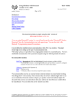
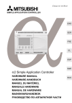
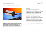
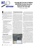
Send documentation comments to [email protected].
C H A P T E R
3
Connecting the Cisco MDS 9216
Switch
The Cisco MDS 9216 Switch provides the following types of ports:
Caution
•
CONSOLE port (Interface Module): An RS-232 port that you can use to
create a local management connection.
•
COM1 port (Interface Module): An RS-232 port that you can use to connect
to an external serial communication device such as a modem.
•
MGMT 10/100 Ethernet port (Interface Module): An Ethernet port that you
can use to access and manage the switch by IP address, such as through the
CLI or Fabric Manager.
•
Fibre Channel ports (Supervisor and Switching Modules): Fibre Channel
ports that you can use to connect to the SAN, or for in-band management.
When running power and data cables in overhead or sub-floor cable trays, we
strongly recommend that power cables and other potential noise sources be
located as far away as practical from network cabling that terminates on Cisco
equipment. In situations where long parallel cable runs cannot be separated by at
least 3.3 ft (1 m), we recommend shielding any potential noise sources by housing
them in a grounded metallic conduit.
Cisco MDS 9216 Switch Hardware Installation Guide
78-16165-01
3-1
Chapter 3
Connecting the Cisco MDS 9216 Switch
Preparing for Network Connections
Send documentation comments to [email protected].
This chapter provides the following information:
•
Preparing for Network Connections, page 3-2
•
Connecting to the Console Port, page 3-2
•
Connecting to the COM1 Port, page 3-4
•
Connecting to the MGMT 10/100 Ethernet Port, page 3-6
•
Connecting to a Fibre Channel Port, page 3-7
Preparing for Network Connections
When preparing your site for network connections to the Cisco MDS 9216
Switch, consider the following for each type of interface, and gather all the
required equipment before connecting the ports:
•
Cabling required for each interface type
•
Distance limitations for each signal type
•
Additional interface equipment required
Connecting to the Console Port
The console port, labeled “Console”, is an RS-232 port with an RJ-45 interface
(see Figure 3-1 on page 3-3). The console port is an asynchronous (async) serial
port; any device connected to this port must be capable of asynchronous
transmission.
We recommend using this port to create a local management connection to set the
IP address and other initial configuration settings before connecting the switch to
the network for the first time.
Note
Connecting the console port to a modem is supported for switches running Cisco
MDS SAN-OS Release 1.2(2a) or later.
Although the console port can be used to connect to a modem, the COM1 port is
recommended for this purpose.
Cisco MDS 9216 Switch Hardware Installation Guide
3-2
78-16165-01
Chapter 3
Connecting the Cisco MDS 9216 Switch
Connecting to the Console Port
Send documentation comments to [email protected].
Caution
If you do want to connect the console port to a modem, do not connect it while
the switch is booting; connect either before powering the switch on or after the
switch has completed the boot process.
You can use the console port to perform the following functions:
Configure the Cisco MDS 9500 from the CLI
•
Monitor network statistics and errors
•
Configure SNMP agent parameters
•
Download software updates
To connect the console port to a computer terminal, the computer must support
VT100 terminal emulation. The terminal emulation software—frequently an
application such as HyperTerminal or Procomm Plus—makes communication
between the Cisco MDS 9216 Switch and computer possible during setup and
configuration.
ST
S
1
SY
STA
TU
MDS 9216
T
EM
Connecting to the Console Port on the Cisco MDS 9216 Switch
SE
Figure 3-1
CONSOLE
MGMT 10/100
COM1
RE
Note
•
1
2
3
4
5
6
7
8
9
10
11
12
13
14
15
16
1
2
3
4
5
6
7
8
9
10
11
12
13
14
15
16
FAN
STATUS
2
91679
FAN-MOD-2
Console
Cisco MDS 9216 Switch Hardware Installation Guide
78-16165-01
3-3
Chapter 3
Connecting the Cisco MDS 9216 Switch
Connecting to the COM1 Port
Send documentation comments to [email protected].
To connect the console port to a computer terminal, follow these steps:
Step 1
Configure the terminal emulator program to match the following default port
characteristics: 9600 baud, 8 data bits, 1 stop bit, no parity.
Step 2
Connect the supplied RJ-45 to DB-9 female adapter to the computer serial port.
We recommend using the adapter and cable provided with the switch.
Step 3
Connect the console cable (a rollover RJ-45 to RJ-45 cable) to the console port
(see Figure 3-1) and to the RJ-45 to DB-9 adapter at the computer serial port.
Note
For configuration instructions, refer to the Cisco MDS 9000 Family Configuration
Guide.
Connecting to the COM1 Port
Note
The COM1 port is not supported for connection to a console.
The COM1 port (labeled “COM1”) is an RS-232 port with a DB-9 interface. You
can use it to connect to an external serial communication device such as a modem.
For information about how to turn off hardware flow control, refer to the Cisco
MDS 9000 Family Configuration Guide.
Note
Connecting the COM1 port to a modem is supported for switches running Cisco
MDS SAN-OS Release 1.2(1a) or later.
Cisco MDS 9216 Switch Hardware Installation Guide
3-4
78-16165-01
Chapter 3
Connecting the Cisco MDS 9216 Switch
Connecting to the COM1 Port
Send documentation comments to [email protected].
1
T
SE
ST
EM
MDS 9216
SY
STA
TU
S
Connecting to the COM1 Port on the Cisco MDS 9216 Switch
CONSOLE
MGMT 10/100
COM1
RE
Figure 3-2
1
2
3
4
5
6
7
8
9
10
11
12
13
14
15
16
1
2
3
4
5
6
7
8
9
10
11
12
13
14
15
16
FAN
STATUS
2
99283
FAN-MOD-2
To connect the COM1 port to a modem, follow these steps:
Step 1
Connect the modem to the COM1 port using the adapters and cables provided
with the accessory kit, as follows: connect the DB-9 serial adapter labeled for use
with the Cisco MDS 9216 Switch to the COM1 port, connect the RJ-45 to DB-25
modem adapter to the modem, then connect the adapters using the RJ-45 to RJ-45
rollover cable (or equivalent crossover cable).
Note
Step 2
Use the green DB-9 adapter that is specifically labeled for use with the
Cisco MDS 9216 Switch. If this adapter is not included in the accessory
kit, you can request one from your customer service representative.
If the default settings for the COM1 port have been modified, refer to the Cisco
MDS 9000 Family Configuration Guide for information regarding verifying and
resetting the default settings.
Cisco MDS 9216 Switch Hardware Installation Guide
78-16165-01
3-5
Chapter 3
Connecting the Cisco MDS 9216 Switch
Connecting to the MGMT 10/100 Ethernet Port
Send documentation comments to [email protected].
The default COM1 settings are as follows:
line Aux:
Speed: 9600 bauds
Databits: 8 bits per byte
Stopbits: 1 bit(s)
Parity: none
Modem In: Enable
Modem Init-String default : ATE0Q1&D2&C1S0=1\015
Statistics: tx:17 rx:0 Register Bits:RTS|DTR
Connecting to the MGMT 10/100 Ethernet Port
Caution
To prevent an IP address conflict, do not connect the MGMT 10/100 Ethernet port
to the network until the initial configuration is complete. For configuration
instructions, refer to the Cisco MDS 9000 Family Configuration Guide.
The MGMT 10/100 Ethernet port (labeled MGMT 10/100) is autosensing and has
an RJ-45 interface (Figure 3-3 on page 3-7). You can use this port to access and
manage the switch by IP address, such as through Fabric Manager.
Cisco MDS 9216 Switch Hardware Installation Guide
3-6
78-16165-01
Chapter 3
Connecting the Cisco MDS 9216 Switch
Connecting to a Fibre Channel Port
Send documentation comments to [email protected].
1
T
SE
ST
EM
MDS 9216
SY
STA
TU
S
Connecting to the MGMT 10/100 Ethernet Port on the Cisco MDS
9216 Switch
CONSOLE
MGMT 10/100
COM1
RE
Figure 3-3
1
2
3
4
5
6
7
8
9
10
11
12
13
14
15
16
1
2
3
4
5
6
7
8
9
10
11
12
13
14
15
16
FAN
STATUS
2
99329
FAN-MOD-2
MGMT 10
/100
To connect the MGMT 10/100 Ethernet port to an external hub, switch, or router,
follow these steps:
Step 1
Step 2
Connect the appropriate modular cable to the MGMT 10/100 Ethernet port:
•
Use modular, RJ-45, straight-through UTP cables to connect the 10/100
management port to an Ethernet switch port or hub.
•
Use a cross-over cable to connect to a router interface.
Connect the other end of the cable to the device.
Connecting to a Fibre Channel Port
The Fibre Channel ports on the switch modules are compatible with LC-type
fiber-optic SFP transceivers and cables (see Figure 3-4 on page 3-9). You can use
the Fibre Channel ports to connect to the SAN or for in-band management. For
information about configuring the switch for inband management, refer to the
Cisco MDS 9000 Family Configuration Guide.
Cisco MDS 9216 Switch Hardware Installation Guide
78-16165-01
3-7
Chapter 3
Connecting the Cisco MDS 9216 Switch
Connecting to a Fibre Channel Port
Send documentation comments to [email protected].
The Cisco MDS 9000 Family supports both Fibre Channel and Gigabit Ethernet
protocol for SFP transceivers. Each transceiver must match the transceiver on the
other end of the cable, and the cable must not exceed the stipulated cable length
for reliable communications. Refer to the release notes for the list of specific
supported SFP transceivers. SFP transceivers can be ordered separately or with
the Cisco MDS 9216 Switch.
Warning
Invisible laser radiation may be emitted from disconnected fibers or
connectors. Do not stare into beams or view directly with optical instruments.
Statement 1051
Caution
Wear an ESD-preventive wrist strap connected to the chassis when handling
transceivers. Keep optical connectors covered when not in use, and do not touch
connector ends. Avoid removing and inserting transceivers more often than
necessary.
Caution
To prevent damage to the fiber optic cables, do not place more tension on them
than the rated limit and do not bend to a radius of less than 1 inch if there is no
tension in the cable, or 2 inches if there is tension in the cable.
Note
Use only Cisco SFP transceivers on the Cisco MDS 9216 Switch. Each Cisco SFP
transceiver is encoded with model information that enables the switch to verify
that the SFP transceiver meets the requirements for the switch. For instructions
specific to the transceiver type, refer to the Installation Notes for the Cisco Small
Form-Factor Pluggable Modules provided with the transceiver.
Cisco MDS 9216 Switch Hardware Installation Guide
3-8
78-16165-01
Chapter 3
Connecting the Cisco MDS 9216 Switch
Connecting to a Fibre Channel Port
Send documentation comments to [email protected].
Figure 3-4
Connecting an LC-Type Cable to an SFP Transceiver
1
94986
2
1 LC plug of fiber optic cable
2 SFP transceiver
Installing an SFP Transceiver and Fiber Optic Cable
To connect an SFP transceiver and fiber optic cable to a Fibre Channel port, follow
these steps:
Step 1
Verify that the transceiver and cable type both have LC-connectors and are the
required type for longwave or shortwave transmission and the required distances.
The transceiver label generally lists the model and wavelength.
Step 2
Remove the dust plug from the port end of the transceiver by pressing the trigger
on top of the plug to release the latch (clicks open) and pulling the plug out.
Step 3
Align and insert the transceiver into the port until the latch clicks. Transceivers
are keyed to prevent incorrect installation; if it does not slide in easily, verify it is
correctly oriented.
Step 4
Remove the dust plugs from the cable and the cable-end of the transceiver.
Step 5
Align and insert the cable end into the transceiver (see Figure 3-4) until the latch
clicks. Cables are keyed to prevent incorrect installation. If the cable does not
slide in easily, verify it is correctly oriented.
Step 6
Connect the other end of the cable to the external end system or switch.
For instructions on verifying connectivity on a module port, refer to the
Cisco MDS 9000 Family Configuration Guide.
Cisco MDS 9216 Switch Hardware Installation Guide
78-16165-01
3-9
Chapter 3
Connecting the Cisco MDS 9216 Switch
Connecting to a Fibre Channel Port
Send documentation comments to [email protected].
Removing an SFP Transceiver and Fiber Optic Cable
Caution
When pulling a cable from a transceiver, grip the body of the connector. Do not
pull on the jacket sleeve, since this can compromise the fiber-optic termination in
the connector.
To remove an SFP transceiver and fiber optic cable from a Fibre Channel port,
follow these steps:
Step 1
Press the latch on top of the SFP to release the lock and gently pull the transceiver
from the port.
Step 2
If desired, remove the cable from the transceiver by pressing the latch on the cable
and pulling the cable from the transceiver.
Step 3
Cover the ends of the transceiver and the cable with the appropriate dust caps.
Maintaining SFP Transceivers and Fiber Optic Cables
SFP transceivers and fiber optic cables must be kept clean and dust-free to
maintain high signal accuracy and prevent damage to the connectors. Attenuation
(loss of light) is increased by contamination, and should be below 0.35 dB.
Maintenance guidelines:
•
SFP transceivers are static sensitive. To prevent ESD damage, wear an
ESD-preventive wrist strap that is connected to the chassis.
•
Do not remove and insert a transceiver more often than necessary. Repeated
removals and insertions can shorten its useful life.
•
Keep all optical connections covered when not in use. If they become dusty,
clean before using to prevent dust from scratching the fiber optic cable ends.
•
Do not touch ends of connectors to prevent fingerprints and other
contamination.
Cisco MDS 9216 Switch Hardware Installation Guide
3-10
78-16165-01
Chapter 3
Connecting the Cisco MDS 9216 Switch
Connecting to a Fibre Channel Port
Send documentation comments to [email protected].
•
Clean regularly; the required frequency of cleaning depends upon the
environment. In addition, clean connectors if they are exposed to dust or
accidentally touched. Both wet and dry cleaning techniques can be effective;
refer to the instructions provided with the SFP transceiver.
•
Inspect routinely for dust and damage. If damage is suspected, clean and then
inspect fiber ends under a microscope to determine if damage has occurred.
Cisco MDS 9216 Switch Hardware Installation Guide
78-16165-01
3-11
Chapter 3
Connecting the Cisco MDS 9216 Switch
Connecting to a Fibre Channel Port
Send documentation comments to [email protected].
Cisco MDS 9216 Switch Hardware Installation Guide
3-12
78-16165-01