1
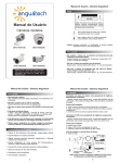
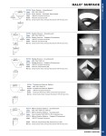
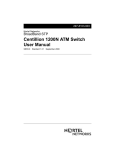
2
CHAPT E R
Preparing for Installation
This chapter provides safety information and describes the tasks you must perform before
you install the LightStream 100 ATM switch.
This chapter contains the following sections:
•
•
•
•
Safety Recommendations
Installation Environmental Conditions
Confirming the Contents of the Shipping Container
LightStream 100 ATM Switch Components
Safety Recommendations
The following guidelines will help to ensure your general safety and protect the equipment:
•
•
•
•
Keep the chassis area clear and dust-free during and after installation.
•
Wear safety glasses if you are working under any conditions that might be hazardous to
your eyes.
•
Do not perform any action that creates a potential hazard to people or makes the
equipment unsafe.
Put the removed chassis cover in a safe place.
Keep tools away from walk areas where you and others could fall over them.
Do not wear loose clothing that could get caught in the chassis. Fasten your tie or scarf
and roll up your sleeves.
Preparing for Installation 2-1
Safety Recommendations
Warning Class 1 laser product. To see this warning in multiple languages, refer to the
“Class 1 Laser Product Warning” section in the “Translated Safety Warnings” appendix.
Warning Do not stare into the beam or view it directly with optical instruments. To see
this warning in multiple languages, refer to the “Laser Beam Warning” section in the
“Translated Safety Warnings” appendix.
Maintaining Safety with Electricity
Follow these guidelines when working on equipment powered by electricity:
Warning Before working on a chassis or working near power supplies, unplug the power
cord on AC units; disconnect the power at the circuit breaker on DC units. To see this
warning in multiple languages, refer to the “Power Supply Disconnection Warning” section
in the “Translated Safety Warnings” appendix.
The device is designed to work with TN power systems. To see this warning in
multiple languages, refer to the “TN Power Warning” section in the “Translated Safety
Warnings” appendix.
Warning
•
Locate the emergency power-off switch for the room in which you are working. Then,
if an electrical accident occurs, you can act quickly to turn OFF the power.
•
•
Before working on the system, turn OFF the power and unplug the power cord.
Disconnect all power before doing the following:
— Installing or removing a chassis
— Working near power supplies
— Performing a software upgrade
•
•
Do not work alone if potentially hazardous conditions exist.
Never assume that power is disconnected from a circuit. Always check.
2-2 Cisco LightStream 100 User Guide
Safety Recommendations
•
Look carefully for possible hazards in your work area, such as moist floors, ungrounded
power extension cables, and missing safety grounds.
•
If an electrical accident occurs, proceed as follows:
— Use caution; do not become a victim yourself.
— Turn off power to the system.
— If possible, send another person to get medical aid. Otherwise, assess the condition
of the victim and then call for help.
— Determine if the person needs rescue breathing or external cardiac compressions;
then take appropriate action.
Preventing Electrostatic Discharge Damage
Electrostatic discharge (ESD) can damage equipment and impair electrical circuitry. It
occurs when electronic components are improperly handled and can result in complete or
intermittent failures.
Always follow ESD-prevention procedures when removing and replacing components.
Ensure that the chassis is electrically connected to earth ground. Wear an ESD-preventive
wrist strap, ensuring that it makes good skin contact. Connect the clip to an unpainted
chassis frame surface to safely channel unwanted ESD voltages to ground. To properly
guard against ESD damage and shocks, the wrist strap and cord must operate effectively. If
no wrist strap is available, ground yourself by touching the metal part of the chassis.
Caution For safety, periodically check the resistance value of the antistatic strap, which
should be within the range of 1 and 10 megohms (Mohms).
Preparing for Installation 2-3
Installation Environmental Conditions
Installation Environmental Conditions
Install the LightStream 100 ATM switch in an area that meets the following conditions:
1 Make sure the LightStream 100 switch remains operational within the temperature and
humidity limits shown in Table 1-3.
2 Allow the following minimum vacant space surrounding the LightStream 100 switch to
ensure proper heat radiation:
— 10 cm (approximately 4 inches) or more—sides
— 10 cm (approximately 4 inches) or more—front and rear
— 10 cm (approximately 4 inches) or more—top
3 Make sure the installation site meets the following criteria:
— Protected from water and chemicals
— Free of shock and vibration
— Horizontal
— Free of excessive dust
— Away from direct sunlight
— Away from devices that generate strong magnetism (for example, a TV or speakers)
Confirming the Contents of the Shipping Container
This section provides information about the contents of containers used to transport the
LightStream 100 ATM switch.
The LightStream 100 switch comes in two containers: the LightStream 100 main unit
container and the LINF card container. Ensure that the containers are labeled with each type
of equipment before opening them.
The LightStream 100 main unit includes the following parts:
•
•
Motherboard (P-8X84)
Bus converter (BCONV) card (P-8X54)
2-4 Cisco LightStream 100 User Guide
LightStream 100 ATM Switch Components
•
•
•
•
•
•
•
Center card (P-8X55-A)
Processor (PROC) card (FSB3523GX, P-8X0R)
Gateway Packet Assembler/Disassembler (GWPAD) card (P-8X86[002])
Fans (three units)
Power supply
Slot covers (16 units)
Shielded power cable (one unit)
The LINF card box contains the LINF card set (a LINF card and front panel with window):
•
•
STS-3c/STM-1 LINF card (P-8X79, P-8X0K)
Transparent Asynchronous Transmitter/Receiver Interface (TAXI) LINF card (P-8X31,
P-8X85)
Note The quantity and type of cards depend on your system configuration.
LightStream 100 ATM Switch Components
References throughout this publication refer to the LightStream 100 ATM switch front and
rear panel layouts. Figure 2-1 shows the front panel layout, and Figure 2-2 shows the rear
panel layout. Figure 2-3 and Figure 2-4 show LightStream 100 switch internal views.
Preparing for Installation 2-5
LightStream 100 ATM Switch Components
Figure 2-1
LightStream 100 ATM Switch Front Panel
Operator
LEDs (16)
H2410
LEDs
Ethernet connection
Reset button
Run LED
Status LED
Failure LED
2-6 Cisco LightStream 100 User Guide
EIA/TIA-232
LightStream 100 ATM Switch Components
LightStream 100 ATM Switch Rear Panel
Cooling fans
H2411
Figure 2-2
AC power connector
Power switch
Preparing for Installation 2-7
LightStream 100 ATM Switch Components
Figure 2-3 LightStream 100 ATM Switch Internal View
Motherboard
Power supply
Fan
Fan
Fan
LINF card
GWPAD card
BCONV card
Center card
PROC card
(VME)
:
:
Gateway Packet Assembler/Disassembler
Line Interface
BCONV
:
Bus Converter
PROC
:
Processor
VME
:
Versa Module Eurocard
2-8 Cisco LightStream 100 User Guide
H2587
GWPAD
LINF
LightStream 100 ATM Switch Components
Figure 2-4
Expanded Internal View (Motherboard)
Subboard ATOM switch
CLKGEN
LINF card
MUX/DMUX
GWPAD card
ATOM SW
CLKGEN
DMUX
GWPAD
LINF
MUX
:
:
:
:
:
:
Asynchronous Transfer Mode Output-Buffer Modular Switch
Clock Generator
Demultiplexer
Gateway Packet Assembler/Disassembler
Line Interface
Multiplexer
H2567
Motherboard
Preparing for Installation 2-9
LightStream 100 ATM Switch Components
2-10 Cisco LightStream 100 User Guide