1
Cisco IAD2430 Series Integrated Access
Devices Hardware Installation Guide
Americas Headquarters
Cisco Systems, Inc.
170 West Tasman Drive
San Jose, CA 95134-1706
USA
http://www.cisco.com
Tel: 408 526-4000
800 553-NETS (6387)
Fax: 408 527-0883
Text Part Number: OL-4234-06
THE SPECIFICATIONS AND INFORMATION REGARDING THE PRODUCTS IN THIS MANUAL ARE SUBJECT TO CHANGE WITHOUT NOTICE. ALL
STATEMENTS, INFORMATION, AND RECOMMENDATIONS IN THIS MANUAL ARE BELIEVED TO BE ACCURATE BUT ARE PRESENTED WITHOUT
WARRANTY OF ANY KIND, EXPRESS OR IMPLIED. USERS MUST TAKE FULL RESPONSIBILITY FOR THEIR APPLICATION OF ANY PRODUCTS.
THE SOFTWARE LICENSE AND LIMITED WARRANTY FOR THE ACCOMPANYING PRODUCT ARE SET FORTH IN THE INFORMATION PACKET THAT
SHIPPED WITH THE PRODUCT AND ARE INCORPORATED HEREIN BY THIS REFERENCE. IF YOU ARE UNABLE TO LOCATE THE SOFTWARE LICENSE
OR LIMITED WARRANTY, CONTACT YOUR CISCO REPRESENTATIVE FOR A COPY.
The following information is for FCC compliance of Class A devices: This equipment has been tested and found to comply with the limits for a Class A digital device, pursuant
to part 15 of the FCC rules. These limits are designed to provide reasonable protection against harmful interference when the equipment is operated in a commercial
environment. This equipment generates, uses, and can radiate radio-frequency energy and, if not installed and used in accordance with the instruction manual, may cause
harmful interference to radio communications. Operation of this equipment in a residential area is likely to cause harmful interference, in which case users will be required
to correct the interference at their own expense.
The following information is for FCC compliance of Class B devices: The equipment described in this manual generates and may radiate radio-frequency energy. If it is not
installed in accordance with Cisco’s installation instructions, it may cause interference with radio and television reception. This equipment has been tested and found to
comply with the limits for a Class B digital device in accordance with the specifications in part 15 of the FCC rules. These specifications are designed to provide reasonable
protection against such interference in a residential installation. However, there is no guarantee that interference will not occur in a particular installation.
Modifying the equipment without Cisco’s written authorization may result in the equipment no longer complying with FCC requirements for Class A or Class B digital
devices. In that event, your right to use the equipment may be limited by FCC regulations, and you may be required to correct any interference to radio or television
communications at your own expense.
You can determine whether your equipment is causing interference by turning it off. If the interference stops, it was probably caused by the Cisco equipment or one of its
peripheral devices. If the equipment causes interference to radio or television reception, try to correct the interference by using one or more of the following measures:
• Turn the television or radio antenna until the interference stops.
• Move the equipment to one side or the other of the television or radio.
• Move the equipment farther away from the television or radio.
• Plug the equipment into an outlet that is on a different circuit from the television or radio. (That is, make certain the equipment and the television or radio are on circuits
controlled by different circuit breakers or fuses.)
Modifications to this product not authorized by Cisco Systems, Inc. could void the FCC approval and negate your authority to operate the product.
The Cisco implementation of TCP header compression is an adaptation of a program developed by the University of California, Berkeley (UCB) as part of UCB’s public
domain version of the UNIX operating system. All rights reserved. Copyright © 1981, Regents of the University of California.
NOTWITHSTANDING ANY OTHER WARRANTY HEREIN, ALL DOCUMENT FILES AND SOFTWARE OF THESE SUPPLIERS ARE PROVIDED “AS IS” WITH
ALL FAULTS. CISCO AND THE ABOVE-NAMED SUPPLIERS DISCLAIM ALL WARRANTIES, EXPRESSED OR IMPLIED, INCLUDING, WITHOUT
LIMITATION, THOSE OF MERCHANTABILITY, FITNESS FOR A PARTICULAR PURPOSE AND NONINFRINGEMENT OR ARISING FROM A COURSE OF
DEALING, USAGE, OR TRADE PRACTICE.
IN NO EVENT SHALL CISCO OR ITS SUPPLIERS BE LIABLE FOR ANY INDIRECT, SPECIAL, CONSEQUENTIAL, OR INCIDENTAL DAMAGES, INCLUDING,
WITHOUT LIMITATION, LOST PROFITS OR LOSS OR DAMAGE TO DATA ARISING OUT OF THE USE OR INABILITY TO USE THIS MANUAL, EVEN IF CISCO
OR ITS SUPPLIERS HAVE BEEN ADVISED OF THE POSSIBILITY OF SUCH DAMAGES.
CCDE, CCENT, Cisco Eos, Cisco Lumin, Cisco Nexus, Cisco StadiumVision, Cisco TelePresence, Cisco WebEx, the Cisco logo, DCE, and Welcome to the Human Network
are trademarks; Changing the Way We Work, Live, Play, and Learn and Cisco Store are service marks; and Access Registrar, Aironet, AsyncOS, Bringing the Meeting To
You, Catalyst, CCDA, CCDP, CCIE, CCIP, CCNA, CCNP, CCSP, CCVP, Cisco, the Cisco Certified Internetwork Expert logo, Cisco IOS, Cisco Press, Cisco Systems,
Cisco Systems Capital, the Cisco Systems logo, Cisco Unity, Collaboration Without Limitation, EtherFast, EtherSwitch, Event Center, Fast Step, Follow Me Browsing,
FormShare, GigaDrive, HomeLink, Internet Quotient, IOS, iPhone, iQuick Study, IronPort, the IronPort logo, LightStream, Linksys, MediaTone, MeetingPlace,
MeetingPlace Chime Sound, MGX, Networkers, Networking Academy, Network Registrar, PCNow, PIX, PowerPanels, ProConnect, ScriptShare, SenderBase, SMARTnet,
Spectrum Expert, StackWise, The Fastest Way to Increase Your Internet Quotient, TransPath, WebEx, and the WebEx logo are registered trademarks of Cisco Systems, Inc.
and/or its affiliates in the United States and certain other countries.
All other trademarks mentioned in this document or website are the property of their respective owners. The use of the word partner does not imply a partnership relationship
between Cisco and any other company. (0809R)
Cisco IAD2430 Series Integrated Access Devices Hardware Installation Guide
Copyright © 2003 - 2008 Cisco Systems, Inc. All rights reserved.
CONTENTS
Preface
vii
Audience
vii
Organization
vii
Conventions
viii
Safety Warnings viii
Warning Definition
ix
Product Serial Number Location
Accessibility
xiv
xv
Related Documentation
xvi
Obtaining Documentation and Submitting a Service Request
CHAPTER
1
Overview of Cisco IAD2430 Series IADs
xvi
1
Overview 1
Cisco IAD2430-24FXS IAD 3
Cisco IAD2431-8FXS IAD 3
Cisco IAD2431-16FXS 4
Cisco IAD2431-1T1E1 IAD 4
Cisco IAD2432-24FXS IAD 5
Cisco IAD2435-8FXS IAD 5
Physical Description
LEDs
6
7
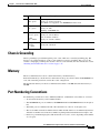
Chassis Grounding
Memory
9
9
Port Numbering Conventions
Specifications
9
10
Software Elements 10
Configuration Connections 10
Configuration Methods 10
Automated Configuration 10
Manual Configuration 11
Interfaces and Service Capabilities
Configuration Options 13
11
Cisco IAD2430 Series Integrated Access Devices Hardware Installation Guide
OL-4234-06
iii
Contents
Deployment Options
CHAPTER
2
13
Planning Your Installation
1
Location and Mounting Requirements 1
Temperature Control and Ventilation 1
Rack-Mounted Installation 1
Wall-Mounted Installation 2
Desktop Installation 2
Access to Chassis 2
Chassis Grounding 2
Power Source 2
Cable Types 3
Distance Limitations for Interface Cables 4
Fast Ethernet Maximum Distance 4
T1/E1-WAN Port Maximum Distances 4
Serial Port Maximum Distances (WIC/VIC Cards) 4
T1/E1-PBX Digital Voice Port Maximum Distances 6
FXS Analog Voice Port Maximum Distance 6
FXO Analog Voice Port Maximum Distance 6
Interference Considerations
CHAPTER
3
6
Installing Cisco IAD2430 Series IADs
1
Safety Recommendations 2
Maintaining Safety with Electricity 2
General Safety Practices 2
Safety Tips 2
Preventing Electrostatic Discharge Damage
Site Log
3
3
Keeping Track—Checklist 3
Installation Checklist 4
Mounting Tools and Equipment
Unpacking and Inspection
4
5
Rack-Mounting the Chassis 6
Mounting Screws 7
Attaching the Brackets 7
Installing the Cisco IAD2430 Series IADs in a Rack
8
Wall-Mounting the Chassis 9
Wall-Mounting the Cisco IAD2430, Cisco IAD2431, and Cisco IAD2432 IADs
9
Cisco IAD2430 Series Integrated Access Devices Hardware Installation Guide
iv
OL-4234-06
Wall-Mounting the Cisco IAD2435 IADs
Desktop-Mounting the Chassis 14
Setting the Cisco IAD2435 on a Desktop
Installing the Ground Connection
Installing a WAN or Voice Card
14
14
17
Connecting Cables 18
LAN and Power Cables 19
Connecting the Input Power 21
Cable 21
Procedure 21
Connecting Input Power on the Cisco IAD2435 IAD 21
Connecting the Console Port to a PC or an ASCII Terminal 22
Cable 22
Procedure 22
Connecting the Auxiliary Port to a Modem 23
Cable 23
Procedure 23
Connecting the Fast Ethernet Port to the Fast Ethernet Switch 23
Cable 23
Procedure 23
WAN and Voice Cables 24
Connecting the RJ-21 Cable in the Velcro Harness 25
Connecting a Serial Interface Port to a CSU/DSU or a Synchronous Modem
Cable 28
Procedure 28
Connecting a T1/E1-WAN Port to the Network Demarcation Device 28
Cable 29
Procedure 29
Connecting the Analog Voice Interface to a Distribution Panel 29
Cable 29
Procedure 30
Connecting the Digital Voice Port to a T1/E1-PBX 30
Cable 30
Procedure 30
Ports, Connectors, and Pinouts
27
31
Cisco IAD2430 Series Integrated Access Devices Hardware Installation Guide
OL-4234-06
v
11
Contents
Remote Terminal Connections (If Applicable) 31
Connecting to a Modem 32
Connecting to a Remote PC 32
Connecting to a Remote ASCII Terminal 32
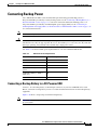
Connecting Backup Power 33
Connecting a Backup Battery to a DC-Powered IAD 33
Connecting an Uninteruptible Power Supply UPS to an AC-Powered Cisco IAD2430 Series IAD
CHAPTER
4
Powering On Cisco IAD2430 Series IADs
Checklist for Power-On
Power-On Procedure
1
1
1
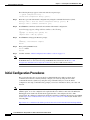
Initial Configuration Procedures 2
Cisco IOS CLI 3
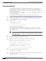
Setup Command Facility 4
Manual Configuration 6
Obtaining Your Network Information 6
Setting the Fast Ethernet Port IP Address 6
Configuring a T1/E1 Port for a WAN Connection
Configuring Digital Voice 8
Verifying and Saving Your Configuration 8
Troubleshooting
34
7
9
INDEX
Cisco IAD2430 Series Integrated Access Devices Hardware Installation Guide
vi
OL-4234-06
Preface
This preface describes the audience, organization, and conventions of this publication, and describes
how to obtain additional documentation.
Audience
This publication is designed for people who have some experience installing networking equipment such
as routers, servers, and switches. The person installing Cisco IAD2430 series integrated access devices
(IADs) should be familiar with networks and telephony equipment as well as with electronic circuitry
and wiring practices and have experience as an electronic or electromechanical technician.
Warning
Only trained and qualified personnel should be allowed to install, replace, or service this equipment.
Statement 1030
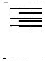
Organization
Table 1
Major Sections of This Guide
Chapter
Title
Description
Chapter 1
Overview of Cisco IAD2430 Features and specifications of Cisco IAD2430 series
integrated access devices.
Series IADs
Chapter 2
Planning Your Installation
Environmental requirements and cable routing
considerations.
Chapter 3
Installing Cisco IAD2430
Series IADs
Instructions for installing Cisco IAD2430 series
integrated access devices and connecting the cables.
Chapter 4
Powering On
Cisco IAD2430 Series IADs
Powering up Cisco IAD2430 series IADs and preparing
for configuration.
Cisco IAD2430 Series Integrated Access Devices Hardware Installation Guide
OL-4234-06
vii
Preface
Conventions
Conventions
Table 2
Installation Guide Conventions
Convention
Description
boldface font
Commands and keywords.
italic font
Variables for which you supply values.
[
Keywords or arguments that appear within square brackets are optional.
]
{x | y | z}
A choice of required keywords appears in braces separated by vertical bars. You
must select one.
screen font
Examples of information displayed on the screen.
boldface screen
Examples of information you must enter.
font
Note
Timesaver
Caution
Tip
<
>
Nonprinting characters, for example passwords, appear in angle brackets in
contexts where italic font is not available.
[
]
Default responses to system prompts appear in square brackets.
Means reader take note. Notes contain helpful suggestions or references to materials not contained in
this publication.
Means the described action saves time. You can save time by performing the action described in the
paragraph.
Means reader be careful. In this situation, you might do something that could result in equipment
damage or loss of data.
Means the following information will help you solve a problem. The tips information might not be
troubleshooting or even an action, but could be useful information, similar to a Timesaver.
Safety Warnings
Safety warnings appear throughout this publication in procedures that, if performed incorrectly, may
harm you. A warning symbol precedes each warning statement. To see translations of the warnings that
appear in this publication, see the Cisco IAD2430 Series Regulatory Compliance and Safety Information
document that accompanied your router or go to the following URL:
http://www.cisco.com/en/US/products/hw/gatecont/ps887/prod_installation_guides_list.html
Cisco IAD2430 Series Integrated Access Devices Hardware Installation Guide
viii
OL-4234-06
Preface
Safety Warnings
Warning Definition
Warning
IMPORTANT SAFETY INSTRUCTIONS
This warning symbol means danger. You are in a situation that could cause bodily injury. Before you
work on any equipment, be aware of the hazards involved with electrical circuitry and be familiar
with standard practices for preventing accidents. To see translations of the warnings that appear in
this publication, refer to the translated safety warnings that accompanied this device. Statement 1071
SAVE THESE INSTRUCTIONS
Waarschuwing
BELANGRIJKE VEILIGHEIDSINSTRUCTIES
Dit waarschuwingssymbool betekent gevaar. U verkeert in een situatie die lichamelijk letsel kan
veroorzaken. Voordat u aan enige apparatuur gaat werken, dient u zich bewust te zijn van de bij
elektrische schakelingen betrokken risico's en dient u op de hoogte te zijn van de standaard
praktijken om ongelukken te voorkomen. Voor een vertaling van de waarschuwingen die in deze
publicatie verschijnen, dient u de vertaalde veiligheidswaarschuwingen te raadplegen die bij dit
apparaat worden geleverd.
Opmerking BEWAAR DEZE INSTRUCTIES.
Varoitus
TÄRKEITÄ TURVALLISUUTEEN LIITTYVIÄ OHJEITA
Tämä varoitusmerkki merkitsee vaaraa. Olet tilanteessa, joka voi johtaa ruumiinvammaan. Ennen
kuin työskentelet minkään laitteiston parissa, ota selvää sähkökytkentöihin liittyvistä vaaroista ja
tavanomaisista onnettomuuksien ehkäisykeinoista. Tässä asiakirjassa esitettyjen varoitusten
käännökset löydät laitteen mukana toimitetuista ohjeista.
Huomautus SÄILYTÄ NÄMÄ OHJEET
Attention
IMPORTANTES INFORMATIONS DE SÉCURITÉ
Ce symbole d'avertissement indique un danger. Vous vous trouvez dans une situation pouvant causer
des blessures ou des dommages corporels. Avant de travailler sur un équipement, soyez conscient
des dangers posés par les circuits électriques et familiarisez-vous avec les procédures couramment
utilisées pour éviter les accidents. Pour prendre connaissance des traductions d'avertissements
figurant dans cette publication, consultez les consignes de sécurité traduites qui accompagnent cet
appareil.
Remarque CONSERVEZ CES INFORMATIONS
Warnung
WICHTIGE SICHERHEITSANWEISUNGEN
Dieses Warnsymbol bedeutet Gefahr. Sie befinden sich in einer Situation, die zu einer
Körperverletzung führen könnte. Bevor Sie mit der Arbeit an irgendeinem Gerät beginnen, seien Sie
sich der mit elektrischen Stromkreisen verbundenen Gefahren und der Standardpraktiken zur
Vermeidung von Unfällen bewusst. Übersetzungen der in dieser Veröffentlichung enthaltenen
Warnhinweise sind im Lieferumfang des Geräts enthalten.
Hinweis BEWAHREN SIE DIESE SICHERHEITSANWEISUNGEN AUF
Cisco IAD2430 Series Integrated Access Devices Hardware Installation Guide
OL-4234-06
ix
Preface
Safety Warnings
Avvertenza
IMPORTANTI ISTRUZIONI SULLA SICUREZZA
Questo simbolo di avvertenza indica un pericolo. La situazione potrebbe causare infortuni alle
persone. Prima di intervenire su qualsiasi apparecchiatura, occorre essere al corrente dei pericoli
relativi ai circuiti elettrici e conoscere le procedure standard per la prevenzione di incidenti. Per le
traduzioni delle avvertenze riportate in questo documento, vedere le avvertenze di sicurezza che
accompagnano questo dispositivo.
Nota CONSERVARE QUESTE ISTRUZIONI
Advarsel
VIKTIGE SIKKERHETSINSTRUKSJONER
Dette varselssymbolet betyr fare. Du befinner deg i en situasjon som kan forårsake personskade. Før
du utfører arbeid med utstyret, bør du være oppmerksom på farene som er forbundet med elektriske
kretssystemer, og du bør være kjent med vanlig praksis for å unngå ulykker. For å se oversettelser
av advarslene i denne publikasjonen, se de oversatte sikkerhetsvarslene som følger med denne
enheten.
Merk TA VARE PÅ DISSE INSTRUKSJONENE
Aviso
INSTRUÇÕES IMPORTANTES DE SEGURANÇA
Este símbolo de aviso significa perigo. O utilizador encontra-se numa situação que poderá ser
causadora de lesões corporais. Antes de iniciar a utilização de qualquer equipamento, tenha em
atenção os perigos envolvidos no manuseamento de circuitos eléctricos e familiarize-se com as
práticas habituais de prevenção de acidentes. Para ver traduções dos avisos incluídos nesta
publicação, consulte os avisos de segurança traduzidos que acompanham este dispositivo.
Nota GUARDE ESTAS INSTRUÇÕES
¡Advertencia!
INSTRUCCIONES IMPORTANTES DE SEGURIDAD
Este símbolo de aviso indica peligro. Existe riesgo para su integridad física. Antes de manipular
cualquier equipo, considere los riesgos de la corriente eléctrica y familiarícese con los
procedimientos estándar de prevención de accidentes. Vea las traducciones de las advertencias
que acompañan a este dispositivo.
Nota GUARDE ESTAS INSTRUCCIONES
Varning!
VIKTIGA SÄKERHETSANVISNINGAR
Denna varningssignal signalerar fara. Du befinner dig i en situation som kan leda till personskada.
Innan du utför arbete på någon utrustning måste du vara medveten om farorna med elkretsar och
känna till vanliga förfaranden för att förebygga olyckor. Se översättningarna av de
varningsmeddelanden som finns i denna publikation, och se de översatta säkerhetsvarningarna som
medföljer denna anordning.
OBS! SPARA DESSA ANVISNINGAR
Cisco IAD2430 Series Integrated Access Devices Hardware Installation Guide
x
OL-4234-06
Preface
Safety Warnings
Cisco IAD2430 Series Integrated Access Devices Hardware Installation Guide
OL-4234-06
xi
Preface
Safety Warnings
Aviso
INSTRUÇÕES IMPORTANTES DE SEGURANÇA
Este símbolo de aviso significa perigo. Você se encontra em uma situação em que há risco de lesões
corporais. Antes de trabalhar com qualquer equipamento, esteja ciente dos riscos que envolvem os
circuitos elétricos e familiarize-se com as práticas padrão de prevenção de acidentes. Use o
número da declaração fornecido ao final de cada aviso para localizar sua tradução nos avisos de
segurança traduzidos que acompanham o dispositivo.
GUARDE ESTAS INSTRUÇÕES
Advarsel
VIGTIGE SIKKERHEDSANVISNINGER
Dette advarselssymbol betyder fare. Du befinder dig i en situation med risiko for
legemesbeskadigelse. Før du begynder arbejde på udstyr, skal du være opmærksom på de
involverede risici, der er ved elektriske kredsløb, og du skal sætte dig ind i standardprocedurer til
undgåelse af ulykker. Brug erklæringsnummeret efter hver advarsel for at finde oversættelsen i de
oversatte advarsler, der fulgte med denne enhed.
GEM DISSE ANVISNINGER
Cisco IAD2430 Series Integrated Access Devices Hardware Installation Guide
xii
OL-4234-06
Preface
Safety Warnings
Cisco IAD2430 Series Integrated Access Devices Hardware Installation Guide
OL-4234-06
xiii
Preface
Product Serial Number Location
Warning
Only trained and qualified personnel should be allowed to install, replace, or service this equipment.
Statement 1030
Warning
Do not use this product near water; for example, near a bath tub, wash bowl, kitchen sink or laundry
tub, in a wet basement, or near a swimming pool. Statement 1035
Warning
Never install telephone jacks in wet locations unless the jack is specifically designed for wet
locations. Statement 1036
Warning
Never touch uninsulated telephone wires or terminals unless the telephone line has been
disconnected at the network interface. Statement 1037
Warning
Avoid using a telephone (other than a cordless type) during an electrical storm. There may be a remote
risk of electric shock from lightning. Statement 1038
Warning
To report a gas leak, do not use a telephone in the vicinity of the leak. Statement 1039
Warning
Do not work on the system or connect or disconnect cables during periods of lightning activity.
Statement 1001
Warning
Ultimate disposal of this product should be handled according to all national laws and regulations.
Statement 1040
Warning
This equipment must be installed and maintained by service personnel as defined by AS/NZS 3260.
Incorrectly connecting this equipment to a general-purpose outlet could be hazardous. The
telecommunications lines must be disconnected 1) before unplugging the main power connector or 2)
while the housing is open, or both. Statement 1043
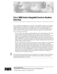
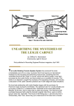
Product Serial Number Location
The serial number label for the Cisco IAD2430 series routers (Cisco IAD2430 through Cisco IAD2432)
is located on the back of the chassis, near the compliance label. The size of the serial number label is
0.25 x 1 inch (0.635 x 2.54 centimeters). It has the letters “SN:” followed by eleven characters. (See
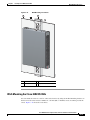
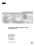
Figure 0-1.) The serial number label for the Cisco IAD2435 series IAD is located on the bottom of the
chassis, near the compliance label. (See Figure 0-2.)
Cisco IAD2430 Series Integrated Access Devices Hardware Installation Guide
xiv
OL-4234-06
Preface
Accessibility
Figure 0-1
Serial Number Location on Cisco IAD2430 Series Routers
AAA
NNN
NXX
XX
IAD2431
103054
-8FXS
AAANNNNXXXX
Figure 0-2
Serial Number Location on Cisco IAD2435-8FXS Routers
Cisco 11 character label
188239, 781-00606-01
SN: AAANNNNXXXX
Accessibility
These integrated access devices can be configured using the Cisco command-line interface (CLI). The
CLI conforms to code 508 because it is text based and it relies on a keyboard for navigation. All
functions of the router can be configured and monitored through the CLI.
For a complete list of guidelines and Cisco products’ adherence to accessibility, see Cisco Accessibility
Products at the following URL:
http://www.cisco.com/web/about/responsibility/accessibility/products
Cisco IAD2430 Series Integrated Access Devices Hardware Installation Guide
OL-4234-06
xv
Preface
Related Documentation
Related Documentation
The Cisco IOS software running your Cisco integrated access device includes extensive features and
functionality. For information that is beyond the scope of this document, or for additional information,
use the resources listed in Table 3 on page xvi.
Timesaver
Table 3
Make sure that you have access to the documents listed in Table 3. See the “Obtaining Documentation
and Submitting a Service Request” section on page xvi for information about obtaining these documents.
Related and Referenced Documents
Cisco Product
Document Title and URL
Cisco IAD2430 series
Cisco IOS software1
•
Cisco IAD2430 Series Integrated Access Devices Hardware Installation Guide (this book)
•
Cisco IAD2430 Series Quick Start Guide
•
Cisco IAD2430 Series Integrated Access Devices Software Configuration Guide
•
Cisco IAD2430 Series Regulatory Compliance and Safety Information
•
Cisco IAD2430 Series Integrated Access Device—Release Notes
1. See the modular reference publications that correspond to the Cisco IOS software release installed on your Cisco IAD2430 series integrated access device.
Obtaining Documentation and Submitting a Service Request
For information on obtaining documentation, submitting a service request, and gathering additional
information, see the monthly What’s New in Cisco Product Documentation, which also lists all new and
revised Cisco technical documentation, at:
http://www.cisco.com/en/US/docs/general/whatsnew/whatsnew.html
Subscribe to the What’s New in Cisco Product Documentation as a Really Simple Syndication (RSS) feed
and set content to be delivered directly to your desktop using a reader application. The RSS feeds are a free
service and Cisco currently supports RSS version 2.0.
Cisco IAD2430 Series Integrated Access Devices Hardware Installation Guide
xvi
OL-4234-06
CH A P T E R
1
Overview of Cisco IAD2430 Series IADs
This chapter provides a brief description of Cisco IAD2430 series integrated access devices (IADs) and
contains the following sections:
•
Overview, page 1-1
•
Physical Description, page 1-6
•
LEDs, page 1-7
•
Chassis Grounding, page 1-9
•
Memory, page 1-9
•
Port Numbering Conventions, page 1-9
•
Specifications, page 1-10
•
Software Elements, page 1-10
•
Interfaces and Service Capabilities, page 1-11
•
Deployment Options, page 1-13
Overview
The Cisco IAD2430 series IADs aggregate multiple channels of data and voice or fax user-side traffic
for transport over single or multiple WAN uplinks. Voice or fax traffic is transported by VoIP or by
Voice over Asynchronous Transfer Mode (VoATM). All platforms support Media Gateway Control
Protocol (MGCP), the signaling protocol H.323, and Session Initiation Protocol (SIP).
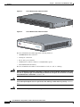
The Cisco IAD2430, Cisco IAD2431, and Cisco IAD2432 series routers consist of five models with a
common front panel (Figure 1). The Cisco IAD2435 series router consists of one model
(Cisco IAD2435-8FXS) with a different front panel (Figure 2). The Cisco IAD2430, Cisco IAD2431,
and Cisco IAD2432 series routers include a slot for the external flash memory card, as well as console,
auxiliary, and flash (CF) memory ports. The front panel, labeled “Cisco IAD2400 Series,” is identical
for all models. However, the back panels, labeled by specific model number, vary considerably,
depending on interfaces, ports, and options. Analog voice ports use an RJ-21 interface.
Cisco IAD2430 Series Integrated Access Devices Hardware Installation Guide
OL-4234-06
1-1
Chapter 1
Overview of Cisco IAD2430 Series IADs
Overview
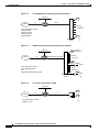
Figure 1-1
Cisco IAD2430 Series IADs Front Panel
2400
88839
CISCO IAD
Figure 1-2
0/0
FE
0/1
CD T1/E1
AL
2/0
2/1
2/2
2/3
FXS
2/4
2/5
2/6
Cisco IAD2
400
2/7
231872
OK
Cisco IAD2435 Series IADs Front Panel
SERIES
The Cisco IAD2430 series IADs support the following interfaces:
•
10/100BASE-T LAN connection
•
T1/E1 port connections
•
RJ-21 analog voice interface
•
WAN interface card/voice interface card (WIC/VIC) options
•
External/internal flash memory
The Cisco IAD2430 series IADs can be mounted in a rack, on a wall, or a desktop.
Warning
There is the danger of explosion if the battery is replaced incorrectly. Replace the battery only with
the same or equivalent type recommended by the manufacturer. Dispose of used batteries according
to the manufacturer’s instructions. Statement 1015
Warning
This unit is intended for installation in restricted access areas. A restricted access area can be
accessed only through the use of a special tool, lock and key, or other means by security. Statement
1017
Warning
No user-serviceable parts inside. Do not open. Statement 1073
Cisco IAD2430 Series Integrated Access Devices Hardware Installation Guide
1-2
OL-4234-06
Chapter 1
Overview of Cisco IAD2430 Series IADs
Overview
Warning
Ultimate disposal of this product should be handled according to all national laws and regulations.
Statement 1040
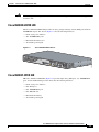
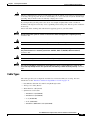
Cisco IAD2430-24FXS IAD
The Cisco IAD2430-24FXS IAD provides 24 analog foreign exchange station (FXS) ports with two
10/100BASE-T ports. The chassis (Figure 1-3) has the following interfaces:
•
RJ-21 analog voice interface
•
Two 10/100BASE-T ports
•
External flash memory slot
•
AC and DC power inputs
Figure 1-3
Cisco IAD2430-24FXS Chassis
VG224-24
88838
FXS
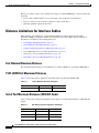
Cisco IAD2431-8FXS IAD
THe Cisco IAD2431-8FXS IAD (Figure 1-4) provides eight analog FXS ports, two 10/100BASE-T
ports, and one T1/E1 WAN port. The chassis has the following interfaces:
•
RJ-21 analog voice interface
•
One T1/E1 port
•
One 10/100BASE-T port
•
One WIC/VIC slot
•
External flash memory
•
AC and DC power inputs
Cisco IAD2430 Series Integrated Access Devices Hardware Installation Guide
OL-4234-06
1-3
Chapter 1
Overview of Cisco IAD2430 Series IADs
Overview
Figure 1-4
Cisco IAD2431-8FXS Chassis
-8FXS
88825
IAD2431
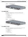
Cisco IAD2431-16FXS
The Cisco IAD2431-16FXS IAD (Figure 1-5) provides sixteen analog FXS ports with two
10/100BASE-T ports and two T1/E1 WAN ports. The chassis has the following interfaces:
•
RJ-21 analog voice interface
•
One T1/E1 port
•
Two 10/100BASE-T ports
•
One WIC/VIC slot
•
External flash memory
•
AC and DC power inputs
Figure 1-5
Cisco IAD2431-16FXS Chassis
88826
IAD2431
-16FXS
Cisco IAD2431-1T1E1 IAD
The Cisco IAD2431-1T1E1 IAD (Figure 1-6) provides one T1/E1 connection to a PBX, one T1/E1
WAN port, and two 10/100BASE-T ports. The chassis has the following interfaces:
•
Two T1/E1 ports
•
Two 10/100BASE-T ports
•
One WIC/VIC slot
•
External flash memory
•
AC and DC power inputs
Cisco IAD2430 Series Integrated Access Devices Hardware Installation Guide
1-4
OL-4234-06
Chapter 1
Overview of Cisco IAD2430 Series IADs
Overview
Figure 1-6
Cisco IAD2431-1T1E1 Chassis
-1T1E1
88827
IAD2431
Cisco IAD2432-24FXS IAD
The Cisco IAD2432-24FXS IAD (Figure 1-7) provides 24 analog FXS ports, two 10/100BASE-T ports,
and two T1/E1 WAN ports. The chassis has the following interfaces:
•
RJ-21 analog voice interface
•
Two T1/E1 ports
•
Two 10/100BASE-T ports
•
One WIC/VIC slot
•
External flash memory
•
AC and DC power inputs
Cisco IAD2432-24FXS Chassis
88824
Figure 1-7
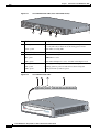
Cisco IAD2435-8FXS IAD
The Cisco IAD2435-8FXS IAD (Figure 1-8) provides eight analog FXS ports, two Fast Ethernet ports,
and one T1/E1 WAN port. The chassis has the following interfaces:
•
RJ-21 analog voice interface
•
One T1/E1 port
•
Two Fast Ethernet ports
•
AC and DC power inputs
Cisco IAD2430 Series Integrated Access Devices Hardware Installation Guide
OL-4234-06
1-5
Chapter 1
Overview of Cisco IAD2430 Series IADs
Physical Description
Figure 1-8
Cisco IAD2435-8FXS Chassis
FXS
IAD2435-
8FXS
WAN
et
CONSOLE
231873
FastEthern
T1/E1
0/1
0/0
AUX
12V DC
SA
Physical Description
Figure 1-9 and Figure 1-10 show the function options of the two IAD243x chassis. All interface slots
are on the back of the chassis.
Figure 1-9
2
3
4
88828
1
Cisco IAD2430 Series IAD Back Panel Function Options
6
5
7
8
9
11 12
13
10
1
Chassis ground connection
2
RJ-21 connector
3
T1/E1 port 1
4
T1/E1 port 0
5
Flash memory slot
6
WIC/VIC slot
7
10/100BASE-T port 1
8
10/100BASE-T port 0
9
AUX port
10 Console port
11 DC power input
1
12 On/off switch
13 AC power input
1. This is not a redundant failover power supply connection. You must use either DC or AC.
Cisco IAD2430 Series Integrated Access Devices Hardware Installation Guide
1-6
OL-4234-06
Chapter 1
Overview of Cisco IAD2430 Series IADs
LEDs
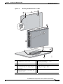
Figure 1-10
Cisco IAD2435 Series IAD Back Panel Function Options
FXS
IAD2435-
8FXS
WAN
et
CONSOLE
231879
FastEthern
T1/E1
0/1
1
0/0
AUX
12V DC
2
3
4
5
SA
6
7
8
1
RJ-21 connector
2
T1/E1 WAN uplink
3
Fast Ethernet port 1
Fast Ethernet port 0
4
Serial port—console or
auxiliary
5
Power connector
6
On/off switch
7
Chassis ground connection
8
Kensington security slot
Note
A Kensington security slot is located on the router back panel. To secure the router to a desktop or other
surface, use the Kensington lockdown equipment.
Note
The FE built-in switch ports provide connections to 10/100BASE-T (10/100-Mbps) Fast Ethernet
networks.
LEDs
The LEDs are located on the back panel of the Cisco IAD2430 series IADs. Figure 1-11 shows LEDs
for the Cisco IAD2430 series IADs. The LEDs for the Cisco IAD2435 series IADs are located on the
front of the chassis. Figure 1-12 shows LEDs for the Cisco IAD2435 series IADs.
Cisco IAD2430 Series Integrated Access Devices Hardware Installation Guide
OL-4234-06
1-7
Chapter 1
Overview of Cisco IAD2430 Series IADs
LEDs
Cisco IAD2400 Series LEDs (Cisco 2432-24FXS shown)
1
95007
Figure 1-11
2
3
4
No LED/Color
Description
1
ACT—green
Green indicates activity—when any of the 24 voice ports is active
in a call (off hook) or when one of the analog ports is in use
Status—green
Green when accessing IAD
2
CF (Slot 0)—green
Green when accessing read or write function
3
Link—green
Indicates link activity
100—green
100BASE-T is active
FDX—green
Green when full duplex is active, off when in half-duplex mode
ACT—green
Blinking green during packet transfer and interrupts
SYS—green
Blinking green for power-on and self-test, then solid green
PWR—green
Solid green when system has power
Figure 1-12
Cisco IAD2435 Series LEDs
2
1
3
FE
OK
OK
0/0
0/0
4
T1/E1
0/1
CD
FXS
AL
2/0
2/1
2/2
2/3
2/4
2/5
2/6
2/7
FE
0/1
CD T1/E1
AL
2/0
2/1
2/2
2/3
FXS
2/4
2/5
2/6
Cisco IAD2
400
2/7
272227
4
SERIES
Cisco IAD2430 Series Integrated Access Devices Hardware Installation Guide
1-8
OL-4234-06
Chapter 1
Overview of Cisco IAD2430 Series IADs
Chassis Grounding
No
LED/Color
LED Color and Description
1
PWR
OK—green
Off—no power
Steady on—normal operation
Slow blink—boot up phase or in ROMMON monitor mode
2
FE ports
0/1—green
Off—No link
Steady on—link
Blinking—TXD/RXD data
3
T1/E1 (carrier
detect)—green
Off—no Carrier Detect
Steady on—Carrier Detect
Off—no Alarm condition
Steady on—Alarm condition
T1/E1
AL—Amber
4
FXS ports 0
through
7—green
Off—On hook
Steady On—Off hook
Chassis Grounding
Chassis grounding is provided through the power cable, which uses a standard grounding plug. The
chassis is also equipped with two 4 x 0.7 screw terminals for chassis grounding. The accessory kit
contains a crimp-type ground lug that attaches to the two screw terminals. For more information, see the
“Installing the Ground Connection” section on page 3-14.
Memory
The Cisco IAD2430 series routers contain flash memory and main memory.
Onboard flash memory contains the Cisco IOS software image, boot flash contains the ROMMON boot
code, and counterfeit prevention contains the cookie configuration.
The default flash memory for the Cisco IAD2430 series IADs is 128 MB. Onboard CPU memory is
256 MB.
Port Numbering Conventions
Port numbering conventions for Cisco IAD2430, IAD2431, and IAD2432 series IADs are as follows:
•
An external flash memory card is numbered CF 0.
•
The 10/100BASE-T ports are numbered 10/100BASE-T 0/0 and 10/100BASE-T 0/1, from right to
left.
•
The T1/E1 ports are numbered T1 1/0 or E1 1/0 and T1 1/1 or E1 1/1, from right to left.
•
The slot for WICs and VICs is numbered slot 0. WIC and VIC interfaces are numbered by interface
with this slot number and an interface number, beginning with 0 and numbered from right to left.
•
FXS voice port numbering begins at 2/0 and extends to 2/7, 2/15, or 2/23, depending on the number
of voice ports.
Cisco IAD2430 Series Integrated Access Devices Hardware Installation Guide
OL-4234-06
1-9
Chapter 1
Overview of Cisco IAD2430 Series IADs
Specifications
Port numbering conventions for the Cisco IAD2435 series IAD are as follows:
•
Fast Ethernet ports are numbered 0 and 1, from left to right.
•
The controller T1/E1 port is numbered T1 0 or E1 0, from left to right.
•
FXS voice port numbering begins at 0 and reaches a maximum of 7, depending on the number of
voice ports, from left to right.
Specifications
For the Cisco IAD2430 series hardware and electrical speicfications, see the Cisco IAD2430 series data
sheets at the following URL:
http://www.cisco.com/en/US/prod/collateral/voicesw/ps6790/gatecont/ps887/ps5321/product_data_she
et09186a008019aded.html
Software Elements
The operating system for the Cisco IAD2430 series IADs is the Cisco IOS software that resides in flash
memory.
Configuration Connections
You can use an ASCII terminal or a PC to configure a Cisco IAD2430 series IAD. The configuration can
be performed in several ways:
•
Locally, with a direct connection through the serial port
•
Remotely, with a connection through the serial port and a modem
•
Through Telnet and TFTP
Configuration Methods
You can configure a Cisco IAD2430 series IAD automatically using the Simple Network-Enabled
Auto-Provision (SNAP) option, or you can configure theCisco IAD2430 series IAD manually using
several methods listed in “Manual Configuration” section on page 1-11.
Automated Configuration
If your Cisco IAD2430 series IAD was ordered with the SNAP option, no on-site configuration is
required. When the Cisco IAD is powered on and connected to the WAN, the SNAP application
downloads the applicable configuration files automatically. For additional information about SNAP, see
the following URL:
http://www.cisco.com/univercd/cc/td/doc/product/software/ios122/122newft/122t/122t8/ftapiad8.htm
Note
The SNAP option is not available on the Cisco IAD2435 IAD.
Cisco IAD2430 Series Integrated Access Devices Hardware Installation Guide
1-10
OL-4234-06
Chapter 1
Overview of Cisco IAD2430 Series IADs
Interfaces and Service Capabilities
Manual Configuration
When you install a Cisco IAD2430 series IAD, see the “Power-On Procedure” section on page 4-1 for
the initial configuration. This configuration sets the basic communication parameters. After the Cisco
IAD is operating and able to communicate, use the procedures in the Cisco IAD2430 Series Software
Configuration Guide to configure the specific services and functions, or to make changes to the existing
configuration.
You can use any of several manual methods for configuring a Cisco IAD2430 series IAD:
•
System configuration dialog
•
Configuration mode—Cisco IOS software command-line interface (CLI)
•
setup command facility—Remote configuration through a LAN or WAN
•
SNMP-based application—CiscoView or HP OpenView
•
HTTP-based configuration server—Provides access to the CLI from a web browser
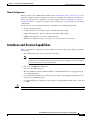
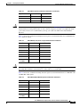
Interfaces and Service Capabilities
Table 1-1 describes the various physical ports and the services that each port type supports, including
the following.
•
Two administrative ports—One console and one auxiliary.
Note
Caution
The Cisco IAD2435 IAD provides a connection to the terminal or PC for software
configuration or troubleshooting. The console port may be configured as a virtual auxiliary
port for dial backup and remote management.
•
One or two 10/100BASE-T LAN ports.
•
One or two Fast Ethernet ports.
•
The Cisco IAD2431 and Cisco IAD2432 IADs for a T1/E1 WAN interface are equipped with one
or two T1/E1 WAN ports.
•
Cisco IAD2430 series IADs for an analog voice user interface are equipped with an RJ-21 port for
connection to a distribution panel.
•
Cisco IAD2432 IADs for adigital voice user interface are equipped with a T1/E1 port for connection
to a PBX.
All Cisco IAD2430 series IADs are customer premises equipment (CPE) only.
Cisco IAD2430 Series Integrated Access Devices Hardware Installation Guide
OL-4234-06
1-11
Chapter 1
Overview of Cisco IAD2430 Series IADs
Interfaces and Service Capabilities
Table 1-1
Cisco IAD2430 Series Interfaces and Service Capabilities
Port
Interface Configurations
Console
port 0/0
Auxiliary
port 0/1
Interface To
Services Supported
Details
EIA/TIA-232 asynchronous ASCII terminal
serial (DCE)
Personal computer
Local administrative
access
RJ-45 physical interface
EIA/TIA-232 asynchronous Modem
serial (DTE)
Remote administrative
access
RJ-45 physical interface
Note
Note
Data backup
The serial port on the
Cisco IAD2435 acts
as either console or
auxiliary.
The serial port on the
Cisco IAD2435 acts
as either console or
auxiliary.
Fast Ethernet 10/100BASE-T (802.3)
ports 0/0, 0/1
LAN
Data
RJ-45 physical interface
RJ-21—8,
16, or 24
analog FXS
voice ports
Analog phone, fax,
or modem
Analog voice/fax or
modem
Provides battery
FXS (loop-start or
ground-start)
Network side of key
system
Ports 2/0 to
2/23
RJ-21 physical interface
8-port FXS, on premise only
16-port FXS, on premise only
Network side of
analog PBX
24-port FXS, on premise only
Ports 0 to 7
(IAD2435
only)
T1/E1 trunk
ports 0,1
Channelized T1/E1
WAN
Carrier network
•
ATM
•
Cisco HDLC
•
PPP
Transport types:
WIC/VIC
slot
HDLC-based data
S0 (serial)
CF4 Slot 0
Built-in CSU/DSU3
Service types:
•
TDM2 trunk
•
Leased lines
T1.403-compliant
1
RJ-48C/CA81A physical
interface
Supports as many as 24 DS0s
WAN
Cisco HDLC
Carrier network
PPP
•
EIA/TIA-232
User equipment
VoIP over PPP
•
EIA/TIA-530/530A
•
EIA/TIA-449
•
V.35
•
X.21
Flash memory
Physical interfaces:
Flash memory card
1. HDLC = High-Level Data Link Control
2. TDM = time-division multiplexing
3. CSU/DSU = channel service unit/data service unit
4. CF = Flash memory
Cisco IAD2430 Series Integrated Access Devices Hardware Installation Guide
1-12
OL-4234-06
Chapter 1
Overview of Cisco IAD2430 Series IADs
Deployment Options
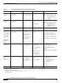
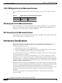
Configuration Options
The following interface options are available in Cisco IAD2430 series IADs:
Table 1-2
Configuration Options
Cisco IAD2430 Series
RJ-211
T1/E12
FE3
WIC/VIC4
CF5
IAD2430-24FXS
Yes
None
2
N/A
External
IAD2431-8FXS
Yes
1
1
Yes
External
IAD2431-16FXS
Yes
1
2
Yes
External
IAD2431-1T1E1
No
2
2
Yes
External
IAD2432-24FXS
Yes
2
2
Yes
External
IAD2435-8FXS
Yes
1
2
N/A
N/A
1. Analog voice interface.
2. T1/E1 ports.
3. 10/100BASE-T ports.
4. WAN interface card (data); voice interface card (voice).
5. Flash (CF) memory.
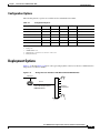
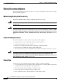
Deployment Options
Figure 1-13 through Figure 1-16 show some typical deployment scenarios for the Cisco IAD2430 series
integrated access devices (IADs).
Figure 1-13
Analog FXS User Interfaces with Metro Ethernet WAN Interface
Ethernet
RJ-21
IAD
Distribution
panel
88997
Analog
telephones
Cisco IAD model number:
IAD2430-24FXS
Cisco IAD2430 Series Integrated Access Devices Hardware Installation Guide
OL-4234-06
1-13
Chapter 1
Overview of Cisco IAD2430 Series IADs
Deployment Options
Figure 1-14
T1/E1 WAN Interface with Analog FXS User Interfaces
Ethernet
WAN
T1
RJ-21
IAD
Analog
telephones
Cisco IAD model number:
IAD2431-8FXS
IAD2431-16FXS
IAD2432-24FXS
IAD2435-8FXS
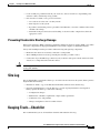
Figure 1-15
WAN Interface with Analog FXS and FXO User Interfaces
Analog
telephones
Ethernet
WAN
88998
Distribution
panel
T1
24 FXS
voice ports
Multiple FXS and FXO
IAD
PBX
Cisco IAD model number:
Cisco IAD2432-24FXS
with
Cisco VIC2-4FXO interface card
4 FXO
voice ports
PBX
Figure 1-16
88996
Distribution
panel
T1/E1 with T1/E1 Interface to PBX
Ethernet
WAN
T1
T1
IAD
Cisco IAD model number:
IAD2431-1T1E1
88995
PBX
Cisco IAD2430 Series Integrated Access Devices Hardware Installation Guide
1-14
OL-4234-06
CH A P T E R
2
Planning Your Installation
Before you install your Cisco IAD2430 series integrated access device (IAD), see the information in this
chapter:
•
Location and Mounting Requirements, page 2-1
•
Distance Limitations for Interface Cables, page 2-4
•
Interference Considerations, page 2-6
Location and Mounting Requirements
The three mounting possibilities for your Cisco IAD are as follows:
•
Rack mounting
•
Wall mounting
•
Desktop mounting
The mounting location must provide the following:
•
Access to the chassis
•
Access to a suitable power source
•
Access to an appropriate earth ground
•
Allowance for adequate heat dissipation and airflow around the chassis
Temperature Control and Ventilation
For proper cooling, the installation location (room, closet, or cabinet) for the Cisco IAD2430 series IAD
should always be well ventilated and provide adequate air circulation. The room temperature should be
maintained at from 32 to 122°F (0 to 50°C).
Note
The Cisco IAD2430, IAD2431, and IAD2432 series IAD chassis is designed for front-to-back airflow.
Rack-Mounted Installation
If the Cisco IAD is installed in an enclosed rack with a ventilation fan at the top, make sure that heated
air drawn upward from other equipment does not prevent adequate cooling.
Cisco IAD2430 Series Integrated Access Devices Hardware Installation Guide
OL-4234-06
2-1
Chapter 2
Planning Your Installation
Location and Mounting Requirements
Caution
Enclosed racks must have adequate ventilation. An enclosed rack should never be overcrowded and
should have louvers and a fan.
If you install the chassis by using slide rails, check for blocked ventilation ports when the chassis is
positioned in the rack or cabinet. Make sure that the ventilation ports of the Cisco IAD are not blocked.
Tip
Baffles can help isolate exhaust air from intake air. Baffles also help draw cooling air through the
cabinet. The best location for the baffles depends on the airflow patterns in the rack. You can test the
airflow by experimenting with various equipment arrangements.
Wall-Mounted Installation
If you install the Cisco IAD on a wall, there should be plenty of space on both sides for adequate airflow
through the chassis.
Desktop Installation
If you place the unit on a desktop, do not stack other equipment or paper on the chassis. Allow plenty of
space for air circulation (front to back). Inadequate ventilation can result in equipment overheating and
damage.
Access to Chassis
Allow space at the back of the chassis for cable connections. Also consider the need to access the chassis
for future upgrades, maintenance, and troubleshooting.
Chassis Grounding
Chassis grounding is provided through the power cable, which uses a standard grounding plug. However,
the chassis also requires a reliable earth ground, using the earth ground lug and hardware provided. For
more information, see the “Installing the Ground Connection” section on page 3-14.
Power Source
A Cisco IAD2430 series IADs with AC power supply autoselects either 100- to 127-V or 200- to 240-V
operation. The Cisco IADs with AC power supply include a 6-foot (1.8-meter) electrical power cord. (A
label near the power cord indicates the correct voltage, frequency, current draw, and power dissipation.)
The Cisco IAD2435 IAD connects to a 60-W, 12-VDC power adapter with the following specifications:
•
Input voltage—85 to 264 VAC
•
Input frequency—47 to 63 Hz
•
Power output—60 W maximum
•
Output voltage—+12 VDC
Cisco IAD2430 Series Integrated Access Devices Hardware Installation Guide
2-2
OL-4234-06
Chapter 2
Planning Your Installation
Location and Mounting Requirements
Caution
The Cisco IAD2430 series chassis provides inputs for both AC and DC power. Design your installation
to use only one type of power. Do not use AC and DC power at the same time. If you do, the unit stops
operating, and you need to reboot it with only a single power source.
If you suspect that your AC power is not clean—for example, if lights flicker often or if there is
machinery with large motors nearby—have a qualified person test the power. Install a power conditioner
if necessary.
Please read all the warnings and cautions before applying power to your Cisco IAD.
Warning
Do not work on the system or connect or disconnect cables during periods of lightning activity.
Statement 1001
Warning
Read the installation instructions before you connect the system to its power source. Statement 1004
Warning
This product relies on the building’s installation for short-circuit (overcurrent) protection. Ensure that
the protective device is rated not greater than: 120 VAC, 15A U.S. (240 VAC, 10A international)
Statement 1005
Warning
The device is designed for connection to TN and IT power systems. Statement 1007
Warning
This unit is intended for installation in restricted access areas. A restricted access area can be
accessed only through the use of a special tool, lock and key, or other means by security. Statement
1017
Cable Types
The cable types that you use depends on which Cisco 2430 series IAD you are using. For more
information see the “Interfaces and Service Capabilities” section on page 1-11.
•
Fast Ethernet cables RJ-45-to-RJ-45 straight-through cables
•
Analog voice cables (RJ-21)
•
T1/E1 interface cable (RJ-48)
•
Synchronous serial cables
– EIA/TIA-232 (DCE/DTE)
– EIA/TIA-449 (DCE/DTE)
– V.35 (DCE/DTE)
– X.21 (DCE/DTE)
– EIA/TIA-530/EIA/TIA-530A (DCE/DTE)
Cisco IAD2430 Series Integrated Access Devices Hardware Installation Guide
OL-4234-06
2-3
Chapter 2
Planning Your Installation
Distance Limitations for Interface Cables
Before you connect a device to the synchronous serial port (labeled SERIAL 0), you need to know the
following:
•
Type of device, DTE or DCE, you are connecting to the synchronous serial interface
•
Type of connector, male or female, required to connect at the device
•
Signaling standard required by the device
Distance Limitations for Interface Cables
When planning your installation, consider distance limitations and potential electromagnetic
interference (EMI) as defined by the Electronic Industries Association (EIA). Distance limitation
information is included for the following IAD ports:
•
Fast Ethernet Maximum Distance, page 2-4
•
T1/E1-WAN Port Maximum Distances, page 2-4
•
Serial Port Maximum Distances (WIC/VIC Cards), page 2-4
•
T1/E1-PBX Digital Voice Port Maximum Distances, page 2-6
•
FXS Analog Voice Port Maximum Distance, page 2-6
•
FXO Analog Voice Port Maximum Distance, page 2-6
Fast Ethernet Maximum Distance
The maximum segment distance for Fast Ethernet is 330 feet (100 meters) (specified in IEEE 802.3).
T1/E1-WAN Port Maximum Distances
Table 2-1 shows the distance limitations for T1/E1 signals (specified in ANSI T1.403).
Table 2-1
T1/E1- WAN Port Distance Limitations
Signal Rate
Distance (Feet)
Distance (Meters)
T1/E1 (CSU)
6200
1890
Serial Port Maximum Distances (WIC/VIC Cards)
Table 2-2 shows the standard relationship between signal rate and maximum distance for EIA/TIA-232
signals.
Table 2-2
EIA/TIA-232 Speed and Distance Limitations
Signal Rate
Distance (Feet)
Distance (Meters)
2400
200
60
4800
100
30
9600
50
15
Cisco IAD2430 Series Integrated Access Devices Hardware Installation Guide
2-4
OL-4234-06
Chapter 2
Planning Your Installation
Distance Limitations for Interface Cables
Table 2-2
Caution
EIA/TIA-232 Speed and Distance Limitations (continued)
Signal Rate
Distance (Feet)
Distance (Meters)
19200
25
7.6
38400
12
3.4
56000
8.6
2.6
EIA/TIA-232 is often used at greater distances than specified in Table 2-2 on page 2-4. If you
understand the electrical problems that can arise and can compensate for them, you might still obtain
good results; however, we recommend that you keep your cable runs within the standard-defined
distances.
Table 2-3 shows the standard relationship between signal rate and maximum distance for EIA/TIA-449,
V.35, and X.21 signals.
Table 2-3
Caution
EIA/TIA-449, V.35, and X.21 Speed and Distance Limitations
Signal Rate
Distance (Feet)
Distance (Meters)
2400
4100
1250
4800
2050
625
9600
1025
312
19200
513
156
38400
256
78
56000
102
31
T1/E1
(1544000)
50
15
The EIA/TIA-449 and V.35 interfaces support data rates up to 2.048 megabits per second (Mb/s).
Exceeding this maximum could result in loss of data and is not recommended.
Table 2-4 shows the standard relationship between signal rate and maximum distance for EIA/TIA-530
and EIA/TIA-530A signals.
Table 2-4
EIA/TIA-530/EIA/TIA-530A Speed and Distance Limitations
Signal Rate
Distance (Feet)
Distance (Meters)
Up to 90000
3940
1200
110000
460
140
120000
425
130
130000
395
120
1000000
330
100
T1/E1
(1544000)
230
70
Cisco IAD2430 Series Integrated Access Devices Hardware Installation Guide
OL-4234-06
2-5
Chapter 2
Planning Your Installation
Interference Considerations
T1/E1-PBX Digital Voice Port Maximum Distances
Table 2-5 shows the maximum distances between the digital voice port of a Cisco IAD and a digital
PBX.
Table 2-5
Digital Voice Port Speed and Distance Limitations
Signal Rate
Distance (Feet)
Distance (Meters)
T1/E1 (CSU)
3000
915
FXS Analog Voice Port Maximum Distance
The maximum distance for a Foreign Exchange System (FXS) is established by a total allowable loop
resistance, including off-hook phone or terminal equipment, of 600 ohm. The maximum distance is
100 meters away from the system as a limitation of Ethernet.
FXO Analog Voice Port Maximum Distance
The maximum distance is determined by the distance between the PBX or other equipment that provides
battery and the connection to the FXO voice port.
Interference Considerations
When you run cables for any significant distance in an electromagnetic field, interference can occur
between the electromagnetic field and the signals on the cables. This has two implications for
installating terminal plant cabling:
•
Unshielded plant cabling can emit radio interference.
•
Strong electromagnetic interference (EMI), especially that caused by lightning or radio transmitters,
can destroy the EIA/TIA-232 drivers and receivers in the Cisco IAD.
If you use twisted-pair cables with a good distribution of grounding conductors in your plant cabling,
emitted radio interference is unlikely.
If you have cables that exceed the recommended distances, or if you have cables that pass between
buildings, give special consideration to the effect of lightning strikes or ground loops. If your site has
these characteristics, consult experts in lightning suppression and shielding. The electromagnetic pulse
caused by lightning or other high-energy phenomena can easily couple enough energy into unshielded
conductors to destroy electronic devices.
Without pulse meters and other special equipment, most data centers cannot resolve the infrequent but
potentially catastrophic problems just described. Take precautions to avoid these problems by providing
a properly grounded and shielded environment and by installing electrical surge suppression.
If you remove any module, you must either install a module in its place or install a cover plate over the
opening. All module openings must be either occupied or covered to prevent electromagnetic
interference.
For advice on the prevention of electromagnetic interference, consult experts in radio frequency
interference (RFI).
Cisco IAD2430 Series Integrated Access Devices Hardware Installation Guide
2-6
OL-4234-06
CH A P T E R
3
Installing Cisco IAD2430 Series IADs
This chapter contains the procedures for installing your Cisco IAD2430 series integrated access device
(IAD) and consists of the following sections:
Tip
•
Safety Recommendations, page 3-2
•
Site Log, page 3-3
•
Keeping Track—Checklist, page 3-3
•
Mounting Tools and Equipment, page 3-4
•
Unpacking and Inspection, page 3-5
•
Rack-Mounting the Chassis, page 3-6
•
Wall-Mounting the Chassis, page 3-9
•
Desktop-Mounting the Chassis, page 3-14
•
Installing the Ground Connection, page 3-14
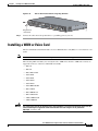
•
Installing a WAN or Voice Card, page 3-17
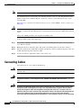
•
Connecting Cables, page 3-18
•
Ports, Connectors, and Pinouts, page 3-31
•
Remote Terminal Connections (If Applicable), page 3-31
•
Connecting Backup Power, page 3-33
While you perform this installation, record your progress and site information. See the suggested format
in the “Keeping Track—Checklist” section on page 3-3.
Warning
Only trained and qualified personnel should be allowed to install, replace, or service this equipment.
Statement 1030
Warning
Read the installation instructions before connecting the system to the power source. Statement 1004
Cisco IAD2430 Series Integrated Access Devices Hardware Installation Guide
OL-4234-06
3-1
Chapter 3
Installing Cisco IAD2430 Series IADs
Safety Recommendations
Safety Recommendations
The following information is included to alert you to safety recommendations and best practices when
working with this equipment.
Maintaining Safety with Electricity
Follow these guidelines when working on equipment powered by electricity.
Warning
Do not work on the system or connect or disconnect cables during periods of lightning activity.
Statement 1001
Warning
Blank faceplates and cover panels serve three important functions: they prevent exposure to
hazardous voltages and currents inside the chassis; they contain electromagnetic interference (EMI)
that might disrupt other equipment; and they direct the flow of cooling air through the chassis. Do not
operate the system unless all cards, faceplates, front covers, and rear covers are in place. Statement
1029
General Safety Practices
Follow these guidelines to ensure personal safety and protect the equipment:
Warning
•
Keep the chassis area clear and dust-free during and after installation.
•
Put the removed chassis cover in a safe place.
•
Keep tools away from walk areas where you and others could fall over them.
•
Do not wear loose clothing that could get caught in the chassis.
•
Wear safety glasses if you are working under any conditions that might be hazardous to your eyes.
This equipment must be installed and maintained by service personnel as defined by AS/NZS 3260.
Incorrectly connecting this equipment to a general-purpose outlet could be hazardous. The
telecommunications lines must be disconnected 1) before unplugging the main power connector or 2)
while the housing is open, or both. Statement 1043
Safety Tips
Use these tips as safety guidelines when installing or working around this equipment.
•
Locate the emergency power-off switch for the room in which you are working. Then, if an electrical
accident occurs, you can act quickly to turn off the power.
•
Disconnect all power before installing or removing a chassis.
•
Do not work alone if potentially hazardous conditions exist.
•
Never assume that power is disconnected from a circuit. Always check.
Cisco IAD2430 Series Integrated Access Devices Hardware Installation Guide
3-2
OL-4234-06
Chapter 3
Installing Cisco IAD2430 Series IADs
Site Log
•
Look carefully for possible hazards in your work area, such as moist floors, ungrounded power
extension cables, and missing safety grounds.
•
If an electrical accident occurs, proceed as follows:
– Use caution; do not become a victim yourself.
– Turn off power to the system.
– If possible, send another person to get medical aid. Otherwise, assess the condition of the victim
and then call for help.
– Determine if the person needs rescue breathing or external cardiac compressions; then take
appropriate action.
Preventing Electrostatic Discharge Damage
Electrostatic discharge (ESD) can damage equipment and impair electrical circuitry. ESD occurs when
electronic components are improperly handled; it can result in complete or intermittent failures.
Always follow ESD-prevention procedures when removing and replacing components.
Caution
•
Ensure that the chassis is electrically connected to earth ground.
•
Wear an ESD-preventive wrist strap, ensuring that it makes good skin contact.
•
Connect the clip to the ESD-strap connection jack (to the left of the power switch on the back of the
chassis) or to an unpainted chassis frame surface.
For safety, periodically check the resistance value of the antistatic strap, which should be between 1 and
10 megohm (Mohm).
Site Log
We recommend that you maintain a Site Log to record all actions relevant to the system. Site Log entries
might include the following:
•
Installation—Print a copy of the Installation Checklist and insert it into the Site Log.
•
Upgrades and maintenance—Use the Site Log to record ongoing maintenance and expansion
history. Update the Site Log to reflect the following:
– Configuration changes
– Maintenance schedules, requirements, and procedures performed
– Comments, notes, and problems
– Changes and updates to the Cisco IOS software
Keeping Track—Checklist
We recommend that you use an installation checklist and maintain a Site Log.
Cisco IAD2430 Series Integrated Access Devices Hardware Installation Guide
OL-4234-06
3-3
Chapter 3
Installing Cisco IAD2430 Series IADs
Mounting Tools and Equipment
Installation Checklist
The Installation Checklist (see Figure 3-1) lists the tasks for installing a Cisco IAD. Print a copy of this
checklist and mark the entries as you complete each task. For each Cisco IAD, include a copy of the
Installation Checklist in your Site Log.
Figure 3-1
Installation Checklist
Installation Checklist for site ______________________________________________
Cisco IAD name/serial number _____________________________________________
Task
Verified by
Date
Background information placed in Site Log
Environmental specifications verified
Site power voltages verified
Installation site prepower check completed
Required tools available
Additional equipment available
Cisco IAD received
Quick start guide received
Regulatory compliance and safety information received
Information packet, warranty card, and Cisco.com card received
Software version verified
Rack, desktop, or wall mounting of chassis completed
Initial electrical connections established
ASCII terminal attached to console port
Modem attached to console port (for remote configuration)
Signal distance limits verified
Startup sequence steps completed
Initial operation verified
Mounting Tools and Equipment
Obtain the following tools and parts needed for installing a Cisco IAD2430 series IAD:
•
Standard flat-blade screwdriver as required for attaching brackets to rack or wall.
•
Phillips screwdriver for attaching brackets to the IAD.
•
Mounting brackets and screws for 24-inch rack, if required.
– Four telco machine screws for installing the chassis in a rack (use the screw size required by the
rack).
•
Screws and anchors for wall mounting, if required.
Cisco IAD2430 Series Integrated Access Devices Hardware Installation Guide
3-4
OL-4234-06
Chapter 3
Installing Cisco IAD2430 Series IADs
Unpacking and Inspection
– Eight wood screws or other fasteners for installing the chassis on a wall. An additional starter
screw can be used to facilitate wall-mounting (does not include Cisco IAD2435 IAD).
– For Cisco IAD2435 IAD—two number-six, 3/4-inch (M3.5 x 20-mm) screws.
•
ESD-preventive wrist strap
In addition, you might need the following external equipment:
Note
•
Console terminal, or personal computer with terminal emulation software
•
PC running terminal emulation software for administrative access
•
Modem for remote access
•
Analog voice RJ-21 cable
•
Digital voice RJ-48 T1/E1 cable
•
Serial, RJ-48, or RJ-45 cables for connecting WAN interface cards (WICs) or voice interface cards
(VICs)
•
CSU/DSU for the serial interfaces
•
Ethernet switch
•
Modem for remote configuration
Serial cables use the Cisco 12-in-1 connector on the WAN connection end.
Unpacking and Inspection
Do not unpack the Cisco IAD2430 series IAD until you are ready to install it. If the installation site is
not ready, keep the chassis in its shipping container to prevent accidental damage.
The IAD, cables, and any optional equipment you ordered might be shipped in more than one container.
When you unpack each shipping container, check the packing list to ensure that you received all the
following items:
•
Cisco IAD2430 series IAD
•
Power cord
Note
Power cords vary, depending upon local requirements.
•
RJ-45-to-DB-25 adapter cable (labeled CON)
•
RJ-45-to-DB-9 adapter cable (labeled AUX)
•
Rack-mounting brackets for 19-inch rack (one pair) with screws for attaching to chassis
Note
•
Rack-mount brackets for 19-inch rack, NEBS grounding kit, and chassis guard for
wall-mounting applications are not included with the Cisco IAD2435-8FXS.
Grounding lug and fasteners
Cisco IAD2430 Series Integrated Access Devices Hardware Installation Guide
OL-4234-06
3-5
Chapter 3
Installing Cisco IAD2430 Series IADs
Rack-Mounting the Chassis
Inspect all items for shipping damage. If anything appears damaged, or if you encounter problems when
installing or configuring your system, contact a customer service representative. (See the “Obtaining
Documentation and Submitting a Service Request” section on page xvi.)
Rack-Mounting the Chassis
Your chassis ship with a pair of brackets for use with a 19-inch rack or for use for wall mounting on the
wall (see Figure 3-9) (Brackets are not included with the Cisco IAD2435 IAD chassis (see Figure 3-3),
but can be ordered through Cisco.). The bracket is shown in Figure 3-2.
Quick Installation Bracket for all Cisco IAD2430 Series Routers Except for
Cisco IAD2435 IAD
88815
Figure 3-2
Note
Rack-mount brackets for 19-inch rack, NEBS grounding kit, and chassis guard for wall-mounting
applications are not included with the Cisco IAD2435-8FXS.
Quick Installation Bracket for Cisco IAD2435-8FXS Routers
280933
Figure 3-3
Cisco IAD2430 Series Integrated Access Devices Hardware Installation Guide
3-6
OL-4234-06
Chapter 3
Installing Cisco IAD2430 Series IADs
Rack-Mounting the Chassis
Mounting Screws
Two sets of mounting screws are provided, in separate packages (Mounting screws are not included with
the Cisco IAD2435 IAD chassis). Take care to use each screw type, and washers as needed, in the
appropriate locations. Table 3-1 clarifies the differences between rack-mounting and wall-mounting
screws.
Table 3-1
Rack-Mounting Screws Versus Wall-Mounting Screws
Rack Mounting
Wall Mounting
•
Eight countersunk Phillips head screws (four
per bracket).
•
Four 6–32 slotted hex screws (two per
bracket) and four plastic washers.
•
Washers are not required.
•
Washers are required.
Attaching the Brackets
To install the chassis in a rack with the front panel forward, attach the brackets as shown in Figure 3-4.
19-Inch Rack Installation—Front Panel Forward
88840
Figure 3-4
CISCO IAD
2400
To install the chassis in a rack with the back panel forward, attach the brackets as shown in Figure 3-5.
19-Inch Rack Installation—Back Panel Forward
88841
Figure 3-5
To install the chassis in a center-mount telco rack, attach the brackets as shown in Figure 3-6.
Cisco IAD2430 Series Integrated Access Devices Hardware Installation Guide
OL-4234-06
3-7
Chapter 3
Installing Cisco IAD2430 Series IADs
Rack-Mounting the Chassis
Telco 19-Inch Rack Installation—Back Panel Forward
88842
Figure 3-6
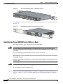
To install the Cisco IAD2435 chassis in a rack with the back panel forward, attach the brackets as shown
in Figure 3-7.
Figure 3-7
IAD2435 Rack Installation with Back Panel Forward
FXS
IAD2435-8
FXS
WAN
T1/E1
0/1
0/0
CONSOLE
AUX
12V DC
SA
231983
FastEthernet
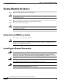
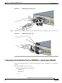
Installing the Cisco IAD2430 Series IADs in a Rack
The following warning applies only when the unit is rack-mounted:
Warning
To prevent bodily injury when mounting or servicing this unit in a rack, you must take special
precautions to ensure that the system remains stable. The following guidelines are provided to ensure
your safety:
This unit should be mounted at the bottom of the rack if it is the only unit in the rack.
When mounting this unit in a partially filled rack, load the rack from the bottom to the top with the heaviest component
at the bottom of the rack.
If the rack is provided with stabilizing devices, install the stabilizers before mounting or servicing the unit in the rack.
Statement 1006
Warning
Take care when connecting units to the supply circuit so that wiring is not overloaded. Statement 1018
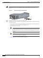
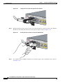
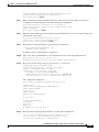
To rack-mount the chassis, follow these steps:
Step 1
Choose one of the methods shown in Figure 3-4 on page 3-7, Figure 3-5 on page 3-7, Figure 3-6 on
page 3-8, or Figure 3-7 on page 3-8, and attach the long side of the mounting brackets to the chassis, as
shown.
Cisco IAD2430 Series Integrated Access Devices Hardware Installation Guide
3-8
OL-4234-06
Chapter 3
Installing Cisco IAD2430 Series IADs
Wall-Mounting the Chassis
Caution
Make sure to use the correct screws for this mounting option (see Table 3-1 on page 3-7).
Screws are included for attaching the brackets to the chassis, but not for installing the chassis in a rack
or on a wall. You need four additional machine screws to install the chassis in a rack. Use the screw size
required by your rack. After the brackets are secured to the chassis, you can rack-mount the chassis.
Step 2
Using screws that you provide, attach the chassis to the rack as shown in Figure 3-8 on page 3-9.
Attaching the Chassis to the 19-Inch Rack
88969
Figure 3-8
Wall-Mounting the Chassis
The following warning applies only when the unit is wall-mounted:
Warning
This unit is intended to be mounted on a wall. Please read the wall-mounting instructions carefully
before beginning installation. Failure to use the correct hardware or to follow the correct procedures
could result in a hazardous situation to people and damage to the system. Statement 248
Wall-Mounting the Cisco IAD2430, Cisco IAD2431, and Cisco IAD2432 IADs
Caution
You can wall-mount the Cisco IAD2430, Cisco IAD2431, or Cisco IAD2432 IAD with either the right
side or the left side facing up; however, the front and back panels must be vertical.
To wall-mount the chassis, follow this procedure:
Step 1
Attach the short side of one bracket to the chassis, as shown in Figure 3-9, using two 6-32 x 1/4 slotted
hex screws (provided). Be sure to use a plastic washer (provided) with each screw; the narrow end of the
washer must fit into the bracket slot, facing the chassis.
Cisco IAD2430 Series Integrated Access Devices Hardware Installation Guide
OL-4234-06
3-9
Chapter 3
Installing Cisco IAD2430 Series IADs
Wall-Mounting the Chassis
Caution
Be sure to use the correct screws and plastic washers for this mounting option. (See Table 3-1 on
page 3-7.)
Attaching the Brackets for Wall-Mounting
88843
Figure 3-9
Step 2
Attach the second bracket to the opposite side of the chassis.
Step 3
Attach the router to the wall using the brackets previously attached and using attachment hardware that
you provide as follows:
•
You can install a starter screw in the wall, and hook the bracket keyhole over the screw. This holds
the unit in place for easy installation of the attachment screws.
•
Attach both brackets to the wall.
•
Note
For attaching to a wall stud, each bracket requires two number 10 wood screws (round- or
pan-head) with number 10 washers, or two number 10 washer-head screws. The screws must
be long enough to penetrate at least 3/4-inch (20-mm) into the supporting wood or metal
wall stud.
Note
For hollow-wall mounting, each bracket requires two wall anchors with washers. Wall
anchors and washers must be size number 10.
Figure 3-10 shows the orientation required for installation.
Cisco IAD2430 Series Integrated Access Devices Hardware Installation Guide
3-10
OL-4234-06
Chapter 3
Installing Cisco IAD2430 Series IADs
Wall-Mounting the Chassis
Figure 3-10
Wall-Mounting the Chassis
3
1
2
103517
CISCO IAD2400
4
1
Wall
2
Bracket
3
Wall stud
4
Keyhole for starter screw
Wall-Mounting the Cisco IAD2435 IADs
You can mount the router on a wall or other vertical surface by using the molded mounting brackets on
the bottom of the router and two number-six, 3/4-inch (M3.5 x 20-mm) screws. You must provide the
screws. Figure 3-11 shows the screw holes.
Cisco IAD2430 Series Integrated Access Devices Hardware Installation Guide
OL-4234-06
3-11
Chapter 3
Installing Cisco IAD2430 Series IADs
Wall-Mounting the Chassis
Caution
If you are mounting the router on drywall, use two hollow-wall anchors (1/8 inch with 5/16-inch drill
bit, or M3 with 8-mm drill bit) to secure the screws. If the screws are not properly anchored, the strain
of the network cable connections could pull the router from the wall.
Figure 3-11
Screw Holes for Wall-Mounting the IAD2435
1
1
2
231984
2
1
1
1
Rubber feet
2
Screw holes
The following conditions must be met when you mount the router:
•
Because you will use the LEDs as status and problem indicators, the LEDs on the front panel must
face upward and must be easily visible.
•
The back panel must face downward to reduce strain on the cable connections.
•
The external 60-W power supply adapter must rest on a horizontal surface such as the floor or a
table. If the power supply is not supported, it could place strain on the powersupply cable and cause
it to disconnect from the connector on the router back panel.
To wall-mount the Cisco IAD2435 IADs, follow these steps:
Step 1
Secure two screws 7 5/8 inches (19.35 centimeters) apart into a wall and 1/8 inch (0.32 centimeter) from
the wall.
Step 2
Hang the router on the screws as shown in Figure 3-12.
Step 3
Place the power supply on a horizontal surface.
Cisco IAD2430 Series Integrated Access Devices Hardware Installation Guide
3-12
OL-4234-06
Chapter 3
Installing Cisco IAD2430 Series IADs
Wall-Mounting the Chassis
Figure 3-12
Mounting the IAD2435 Router on a Wall
2
1
3
7
4
6
231985
5
1
Two number-six, 3/4-in. screws
2
Distance between the two screws
(7 5/8 in. [19.35 cm])
3
Cisco IAD2435 router
4
Mounting brackets
5
Maximum distance between the router and 6
the external 60-W power supply adapter
(6 ft [1.8 m])
7
Distance between the screw and the wall
(1/8 in. [0.32 cm])
Horizontal surface for placing the external
60-W power supply adapter
Cisco IAD2430 Series Integrated Access Devices Hardware Installation Guide
OL-4234-06
3-13
Chapter 3
Installing Cisco IAD2430 Series IADs
Desktop-Mounting the Chassis
Desktop-Mounting the Chassis
Step 1
Verify that a suitable AC power outlet is available.
Caution
Do not plug this unit into an AC outlet that does not have a UL-certified receptacle that is properly tied
into the building ground.
Step 2
Place the four rubber feet (from the accessory kit) in the four indentations on the underside of the chassis.
This helps provide proper airflow through and around the chassis.
Step 3
Place the Cisco IAD on the desktop.
Caution
Do not place anything on top of the chassis that weighs more than 10 lb (4.5 kg). Excessive weight on
top can damage the chassis.
Setting the Cisco IAD2435 on a Desktop
You can place Cisco IAD2435 on a desktop.
Caution
Do not place anything on top of the router that weighs more than 5 pounds (2.25 kg), and do not stack
routers on a desktop. Excessive distributed weight of more than 5 pounds, or pound point load of 5
pounds on top could damage the chassis.
Installing the Ground Connection
Warning
This equipment must be grounded. Never defeat the ground conductor or operate the equipment in the
absence of a suitably installed ground conductor. Contact the appropriate electrical inspection
authority or an electrician if you are uncertain that suitable grounding is available. Statement 1024
Warning
AC connected units must have a permanent ground connection in addition to the power cable ground
wire. NEBS-compliant grounding satisfies this requirement. Statement 284
Warning
This equipment needs to be grounded. Use a green and yellow 12 to 14 AWG ground wire to connect
the host to earth ground during normal use. Statement 242
Cisco IAD2430 Series Integrated Access Devices Hardware Installation Guide
3-14
OL-4234-06
Chapter 3
Installing Cisco IAD2430 Series IADs
Installing the Ground Connection
Warning
The importance of proper grounding cannot be overemphasized. It will minimize the potential for
damage to your system and maximize safety at the system site. We recommend you consult a licensed
electrician or your local electric utility company if you have any questions. Statement 269
Warning
A ground wire must always be a single piece of wire. Never splice two wires together for a ground.
Corrosion and weathering can lead to a poor connection at the splice, making the ground ineffective
and dangerous. Statement 270
Warning
Use copper conductors only. Statement 1025
Warning
Installation of the equipment must comply with local and national electrical codes. Statement 1074
You must connect the chassis to a reliable earth ground; the ground wire must be installed in accordance
with local electrical safety standards.
•
For NEBS-compliant grounding, use size AWG 6 (13 mm2) wire and the ground lug provided in the
accessory kit.
•
For NEC-compliant grounding, use size AWG 14 (2 mm2) or larger wire and an appropriate
user-supplied ring terminal.
•
For EN/IEC 60950-compliant grounding, use size AWG 18 (1 mm2) or larger wire and an
appropriate user-supplied ring terminal.
To ground the chassis, follow these steps:
Step 1
Tip
Locate a suitable ground location.
Use a multimeter to measure the resistance between various ground locations, such as the following:
•
Between the ground of a junction box (outlet) and the ground of a power tap
•
Between the ground of a junction box and a metal water pipe
•
Between the Cisco IAD chassis and the ground of a power tap
•
Between the Cisco IAD chassis and the ground of a junction box
A good ground connection should read between 0.0 and 0.5 ohm.
Step 2
Step 3
Strip one end of the ground wire to the length required for the ground lug or terminal.
•
For the NEBS ground lug—approximately 0.75 inch (20 millimeters)
•
For user-provided ring terminal—as required
Crimp the ground wire to the ground lug or ring terminal, using a crimp tool of the appropriate size. (See
Figure 3-13.)
Cisco IAD2430 Series Integrated Access Devices Hardware Installation Guide
OL-4234-06
3-15
Chapter 3
Installing Cisco IAD2430 Series IADs
Installing the Ground Connection
Crimping a Ground Lug onto the Ground Wire
10360
Figure 3-13
Step 4
Attach the ground lug or ring terminal to the chassis as shown in Figure 3-14, Figure 3-15, or
Figure 3-16. For the ground lug, use the two screws with captive locking washers provided. For a ring
terminal, use one of the screws provided. Use a number 2 Phillips screwdriver, and tighten the screws
to a torque of 8 to 10 in-lb (0.9 to 1.1 N-m).
Note
You can orient the crimped end of the ground lug in either direction (right or left).
Figure 3-14
NEBS-Compliant Chassis Ground Connection Using Ground Lug
88844
Ground lug
Figure 3-15
Ground Lug Location on the Cisco IAD2435 IAD
FXS
IAD2435-
8FXS
WAN
et
CONSOLE
232068
FastEthern
T1/E1
0/1
0/0
AUX
12V DC
SA
1
1
Grounding lug
Cisco IAD2430 Series Integrated Access Devices Hardware Installation Guide
3-16
OL-4234-06
Chapter 3
Installing Cisco IAD2430 Series IADs
Installing a WAN or Voice Card
Chassis Ground Connection Using Ring Terminal
103512
Figure 3-16
Ring terminal
attachment
Step 5
Connect the other end of the ground wire to a grounding point at your site.
Installing a WAN or Voice Card
The Cisco IAD2430 series IADs include a slot for a WAN interface card (WIC) or a voice interface card
(VIC).
Note
The Cisco IAD2435 router is a fixed-configuration router and does not support interface cards.
The following WICs and VICs (also used by the Cisco 2600 series and Cisco 3600 series routers) are
supported in releases of the Cisco IAD2430 series IADs:
Warning
•
WIC-1T
•
WIC-2T
•
WIC-1DSU-T1/E1
•
VIC2-2FXS
•
VIC2-4FXS
•
VIC2-2FXO
•
VIC2-4FXO
•
VIC2-2BRI-NT/TE
•
WIC-1ADSL
•
WIC-1SHDSL-V2
•
WIC-1ADSL-DG
•
VWIC-2MFT-T1/E1
•
VWIC-2MFT-E1
For connections outside the building where the equipment is installed, the following ports must be
connected through an approved network termination unit with integral circuit protection.
FXS/T3/E3. Statement 1044
Cisco IAD2430 Series Integrated Access Devices Hardware Installation Guide
OL-4234-06
3-17
Chapter 3
Installing Cisco IAD2430 Series IADs
Connecting Cables
Note
Contact your Cisco account representative for the most recent, supported cards.
For detailed information on installing and connecting interface cards, see “Installing WAN and Voice
Interface Cards in Cisco Modular Routers,” in the Cisco Interface Cards Installation Guide, at the
following URL:
http://www.cisco.com/univercd/cc/td/doc/product/access/acs_mod/cis2600/hw_inst/wic_inst/wic_doc/
index.htm
Caution
WAN and voice interface cards do not support online insertion and removal (hot swapping). Before
inserting a card into the Cisco IAD chassis, you must turn off electrical power and disconnect network
cables.
Always use an ESD-preventive wrist strap before handling cards.
To install a WIC or VIC, follow these steps:
Step 1
Use a number 2 Phillips screwdriver to remove the screws holding the metal plate over the card slot
cover. Remove the plate.
Step 2
Holding the interface card by the edges, line up the card with the guides on both sides of the slot.
Step 3
Insert the card in the slot. Push until it is firmly seated in the connector and the front panel of the card
is flush with the back panel of the Cisco IAD.
Step 4
Use the screwdriver to tighten the captive screws on the card.
Connecting Cables
Cisco IAD ports are color-coded for identification.
Warning
Do not work on the system or connect or disconnect cables during periods of lightning activity.
Statement 1001]
Warning
This product relies on the building’s installation for short-circuit (overcurrent) protection. Ensure that
the protective device is rated not greater than: 120 VAC, 15A (240 VAC, 10A international) Statement
1005
Warning
To prevent accidental discharge in the event of a power line cross, route on-premise wiring away
from power cables and off-premise wiring, or use a grounded shield to separate the on-premise
wiring from the power cables and off-premise wiring. A power line cross is an event, such as a
lightning strike, that causes a power surge. Off-premise wiring is designed to withstand power line
crosses. On-premise wiring is protected from power line crosses by a device that provides
overcurrent and overvoltage protection. Nevertheless, if the on-premise wiring is in close proximity
Cisco IAD2430 Series Integrated Access Devices Hardware Installation Guide
3-18
OL-4234-06
Chapter 3
Installing Cisco IAD2430 Series IADs
Connecting Cables
to, or not shielded from, the off-premise wiring or power cables during a lightning strike or power
surge, the on-premise wiring can carry a dangerous discharge to the attached interface, equipment,
and nearby personnel. Statement 338
Table 3-2 shows the results of the NEBS Type 1/3 power line cross tests performed on the
Cisco IAD2430 series FXS ports.
Table 3-2
Note
Results of the NEBS Power Line Cross Tests on FXS Ports
NEBS Tests
Results
50 V/0.33 A; 15 minutes
Passed
100 V/0.17 A; 15 minutes
Passed
200 V/1.00 A; 1–second pulses, 60 repetitions
Passed
The installation must comply with all applicable codes.
LAN and Power Cables
The LAN and power cables and connections are described in Table 3-3 and shown in Figure 3-17 and
Figure 3-18.
Table 3-3
LAN, Administrative Access, and Power Cable Selection
Port or Connection
Color or Type Connected To
Cable
Fast Ethernet
Yellow
Fast Ethernet switch
Straight-through Fast Ethernet cable (not included)
Console
Light blue
PC or ASCII terminal
communication (COM) port
RJ-45-to-DB-9 console cable (included)
Auxiliary
Black
Modem for remote access
RJ-45-to-DB-25 auxiliary cable (included)
Power (not shown)
Power
100–240 VAC, 50–60 Hz
Grounding power cord (included)1
1. Power cables vary to meet local requirements.
Cisco IAD2430 Series Integrated Access Devices Hardware Installation Guide
OL-4234-06
3-19
Chapter 3
Installing Cisco IAD2430 Series IADs
Connecting Cables
Figure 3-17
LAN and Administrative Access Connections
1
2
3
95091
Cisco IAD2430 series
4
5
6
Ethernet switch
Modem
PC
1
Fast Ethernet port
2
Console port
3
AUX port
4
Fast Ethernet (straight-through)
5
RJ-45-to-DB-9 console cable
6
RJ-45-to-DB-25 auxiliary cable
Figure 3-18
LAN, Administrative Access, and Connections (Cisco IAD2435 IAD)
FXS
IAD2435-
8FXS
WAN
et
CONSOLE
232070
FastEthern
T1/E1
0/1
0/0
AUX
12V DC
1
3
SA
2
4
Ethernet hub
PC
Cisco IAD2430 Series Integrated Access Devices Hardware Installation Guide
3-20
OL-4234-06
Chapter 3
Installing Cisco IAD2430 Series IADs
Connecting Cables
1
Fast Ethernet port
2
Serial port—console or auxiliary
3
Fast Ethernet (straight-through)
4
RJ-45-to-DB-9 console cable
Connecting the Input Power
To connect input power to the Cisco IAD, use the procedure in this section.
Caution
The Cisco IAD2430 series chassis provides inputs for both AC and DC power. Design your installation
to use only one type of power. Do not use AC and DC power at the same time. If you do, the unit stops
operating, and you must reboot it with only a single power source.
Cable
The AC power cable is used for this application.
Procedure
Step 1
Connect the AC power cable (supplied) to the recessed power plug on the back of the concentrator.
Step 2
Plug the cable into a power source with a voltage of 100 to 240 VAC.
Connecting Input Power on the Cisco IAD2435 IAD
To connect input power to the Cisco IAD2435, perform the following steps:
Step 1
Connect the router to an AC power outlet as shown in Figure 3-19.
Step 2
To secure the power cord to the router, attach the power lock clip to the power cord, and slide the clip
to the end of the DC plug. See location 1 in Figure 3-19.
Cisco IAD2430 Series Integrated Access Devices Hardware Installation Guide
OL-4234-06
3-21
Chapter 3
Installing Cisco IAD2430 Series IADs
Connecting Cables
Figure 3-19
Connecting the External Power Supply to the Cisco IAD2435
FXS
IAD2435-8
FXS
WAN
FastEthernet
0/1
CONSOLE
0/0
272268
T1/E1
AUX
12V DC
SA
1
2
4
3
1
Power lock clip
2
Power cord
3
Power adapter
4
AC plug
Connecting the Console Port to a PC or an ASCII Terminal
To connect the console port to a PC that is running terminal emulation software, use the procedure in
this section.
Note
The console port does not support hardware flow control.
Cable
Use an RJ-45-to-DB-9 console cable (see location 5 in Figure 3-17 on page 3-20).
Procedure
Step 1
Connect the cable between the Cisco IAD console port and the serial port on the PC or ASCII terminal.
Step 2
Configure the terminal emulation software requirements:
•
9600 baud
•
8 data bits
•
1 stop bit
•
no parity
Cisco IAD2430 Series Integrated Access Devices Hardware Installation Guide
3-22
OL-4234-06
Chapter 3
Installing Cisco IAD2430 Series IADs
Connecting Cables
•
no flow control
Connecting the Auxiliary Port to a Modem
To connect the auxiliary port to a modem, use the procedure in this section.
Cable
Use an RJ-45-to-DB-25 auxiliary cable (labeled Modem).
Procedure
Step 1
Connect the cable from the auxiliary port (black) to the DB-25 port on the modem. (See location 6 in
Figure 3-17 on page 3-20.)
Step 2
Configure the modem:
Note
a.
Match the transmission speed of the auxiliary port (default is 9600 baud).
b.
Set the hardware flow control for Data Carrier Detect (DCD) and Data Terminal Ready (DTR)
operation.
The baud rate for the auxiliary (and console) port can be configured in software for 1200, 2400, 4800,
19200, 38400, 57600, or 115200.
Connecting the Fast Ethernet Port to the Fast Ethernet Switch
To connect a Fast Ethernet port to the Fast Ethernet switch, use the procedure in this section.
Cable
Use a straight-through Fast Ethernet cable (not included).
Procedure
Step 1
Connect the cable from a Fast Ethernet port to an available port on the Fast Ethernet switch. (See
location 4 in Figure 3-17 on page 3-20.)
Step 2
Connect the second cable if it is required.
Note
Not all models have two ports.
Cisco IAD2430 Series Integrated Access Devices Hardware Installation Guide
OL-4234-06
3-23
Chapter 3
Installing Cisco IAD2430 Series IADs
Connecting Cables
WAN and Voice Cables
Warning
Note
For connections outside the building where the equipment is installed, the following ports must be
connected through an approved network termination unit with integral circuit protection.
FXS/T3/E3 Statement 1044
The following warning also applies to Cisco IAD2430 units that have an RJ-21 interface.
Warning
Before opening the unit, disconnect the telephone-network cables to avoid contact with
telephone-network voltages. Statement 1041
Warning
This equipment contains a ring signal generator (ringer), which is a source of hazardous voltage. Do
not touch the RJ-11 (phone) port wires (conductors), the conductors of a cable connected to the RJ-11
port, or the associated circuit-board when the ringer is active. The ringer is activated by an incoming
call. Statement 1042
These cables and connections are described in Table 3-4 on page 3-24 and shown in Figure 3-20 on
page 3-25.
Table 3-4
WAN and Voice Cable Selection
Port or Interface
Color or Type
Connected To
Cable
T1/E1
WAN
Light green
WAN
RJ-48 T1/E1 cable (not included)
T1/E1
Digital voice
RJ-48C
Digital PBX
RJ-48 T1/E1 cable (not included)
Analog voice
FXS
RJ-21
Distribution panel
RJ-21-to-RJ-21 straight-through cable
(not included)
WIC-2T
Serial
Cisco 12-in-1
serial port
connector
CSU/DSU and serial
network or equipment
Serial transition cable matching signaling
protocol (EIA/TIA-232, EIA/TIA-449,
V.35, X.21, or EIA-530) and operating
mode (DTE or DCE) (not included)
WIC-1DSU-T1/E1 WAN
Light green
WAN
RJ-48 T1/E1 cable (not included)
VIC2-4FXO
RJ-11
Station side of analog PBX
RJ-11 cable (not included)
FXO
Cisco IAD2430 Series Integrated Access Devices Hardware Installation Guide
3-24
OL-4234-06
Chapter 3
Installing Cisco IAD2430 Series IADs
Connecting Cables
Figure 3-20
WAN and Voice Connections
To CO
Distribution panel
1
2
95092
Cisco IAD2430 series
3
Network
demarcation
1
RJ-21 cable
2
3
RJ-48 straight-through cable
RJ-45 cable (through a patch panel) to central
office (CO)
Connecting the RJ-21 Cable in the Velcro Harness
For the Cisco IAD2430 series models that have a Velcro harness available for the RJ-21 cable (see
Figure 3-21), follow these steps:
Figure 3-21
Cisco IAD2430 Series RJ-21 Velcro Harness
FXS
IAD2435-
8FXS
WAN
et
CONSOLE
281199
FastEthern
T1/E1
0/1
0/0
AUX
12V DC
Step 1
SA
Slip the RJ-21 cable connector through the Velcro strap (see Figure 3-22).
Cisco IAD2430 Series Integrated Access Devices Hardware Installation Guide
OL-4234-06
3-25
Chapter 3
Installing Cisco IAD2430 Series IADs
Connecting Cables
Figure 3-22
Sliding the RJ-21 Cable Through the Velcro Harness
FXS
IAD2435-8
FXS
WAN
FastEthern
T1/E1
Step 2
0/1
281200
et
0/0
Push the male RJ-21 cable connector into the slot of the female RJ-21 connection on the router. Push the
male RJ-21 cable firmly until the RJ-21 security clips are firmly seated (see Figure 3-23).
Figure 3-23
Pushing the RJ-21 Cable in to the Cisco IAD2435 IAD
FXS
IAD2435-8
FXS
WAN
FastEthern
T1/E1
Step 3
0/1
0/0
281201
et
Use a number 2 (flat or Phillips screwdriver) to attach the captive screws on the RJ-21 male connector
(see Figure 3-24).
Cisco IAD2430 Series Integrated Access Devices Hardware Installation Guide
3-26
OL-4234-06
Chapter 3
Installing Cisco IAD2430 Series IADs
Connecting Cables
Figure 3-24
Tightening the Captive Screws
FXS
IAD2435-8
FXS
WAN
FastEthern
T1/E1
Step 4
0/1
0/0
281202
et
Pull the Velcro strap up until tight, then down and affix the strap to other Velcro side (see Figure 3-25).
Figure 3-25
Tightening the Velcro Strap
FXS
IAD2435-8
FXS
WAN
T1/E1
0/1
et
0/0
281203
FastEthern
Connecting a Serial Interface Port to a CSU/DSU or a Synchronous Modem
Use the procedure in this section to connect the serial interface port to a CSU/DSU or to a synchronous
modem.
The serial port (S0) can operate as follows:
•
DTE or DCE with the following signaling:
– EIA/TIA-232
– EIA-TIA-449
– V.35
Cisco IAD2430 Series Integrated Access Devices Hardware Installation Guide
OL-4234-06
3-27
Chapter 3
Installing Cisco IAD2430 Series IADs
Connecting Cables
– X.21
•
Note
DTE only with EIA/TIA -530 signaling
DTE ports require external clocking provided by a DCE device such as a CSU/DSU.
Cable
The type of cable you connect to the serial port automatically sets the port for DTE or DCE operation
and establishes the signaling standard.
Procedure
Use the procedure in this section to connect external equipment to the Cisco 2430 series IAD.
Step 1
Connect the appropriate serial interface cable between the WAN serial port and the serial port connector
(see Figure 3-26).
Figure 3-26
Serial Port Connection
SERIAL1
CONN
SERIAL2
WIC
2T
88966
CONN
Cisco 12-in-1
Serial transition cable
Step 2
CSU/DSU
Connector for: EIA/TIA-232
EIA/TIA-449
V.35 (shown)
X.21
EIA-530
Connect the external equipment (CSU/DSU or other serial device).
Connecting a T1/E1-WAN Port to the Network Demarcation Device
To connect the T1/E1 port to a network demarcation device, use the procedure in this section.
Warning
To avoid electric shock, do not connect safety extra-low voltage (SELV) circuits to telephone-network
voltage (TNV) circuits. LAN ports contain SELV circuits, and WAN ports contain TNV circuits. Some
LAN and WAN ports both use RJ-45 connectors. Use caution when connecting cables. Statement 1021
Cisco IAD2430 Series Integrated Access Devices Hardware Installation Guide
3-28
OL-4234-06
Chapter 3
Installing Cisco IAD2430 Series IADs
Connecting Cables
Warning
Note
Hazardous network voltages are present in WAN ports regardless of whether power to the router is
OFF or ON. To avoid electric shock, use caution when working near WAN ports. When detaching
cables, detach the end away from the router first. Statement 1026
The T1/E1-WAN port has a built-in CSU/DSU for connecting to a service provider’s network interface.
Cable
Use an RJ-48 T1/E1 cable (not included).
Procedure
Step 1
Connect the RJ-48 T1/E1 cable to the T1-WAN port (marked T1-WAN on a light-green label).
Step 2
Connect the RJ-48C/CA81A jack to the network demarcation device (telco demarcation or equivalent).
(See Figure 3-27.)
T1/E1 Port to Network Connection
88967
Figure 3-27
Network
demarcation
Connecting the Analog Voice Interface to a Distribution Panel
To connect the multiport analog voice interface to a distribution panel, which connects to telephones,
faxes, or analog PBX equipment, use the procedure in this section.
Cable
Use an RJ-21 cable with Amphenol 50-pin connectors (not included).
Cisco IAD2430 Series Integrated Access Devices Hardware Installation Guide
OL-4234-06
3-29
Chapter 3
Installing Cisco IAD2430 Series IADs
Connecting Cables
Warning
This equipment contains a ring signal generator (ringer), which is a source of hazardous voltage. Do
not touch the RJ-11 (phone) port wires (conductors), the conductors of a cable connected to the RJ-11
port, or the associated circuit-board when the ringer is active. The ringer is activated by an incoming
call. Statement 1042
Procedure
Step 1
Connect the RJ-21 cable from the analog voice multiport to the distribution panel. See Figure 3-28.
Analog Voice Connection
88968
Figure 3-28
Distribution panel
RJ-21 cable
Step 2
Use the strap to secure the cable in place.
Connecting the Digital Voice Port to a T1/E1-PBX
To connect the digital voice port to a digital PBX, use the procedure in this section.
Cable
Use an RJ-48 T1/E1 cable (not included).
Procedure
Step 1
Connect the RJ-48 T1/E1 cable to the T1/E1 port. See Figure 3-29.
Cisco IAD2430 Series Integrated Access Devices Hardware Installation Guide
3-30
OL-4234-06
Chapter 3
Installing Cisco IAD2430 Series IADs
Ports, Connectors, and Pinouts
Digital Voice Connection
88999
Figure 3-29
RJ-48 T1 cable
Step 2
Digital PBX
or channel bank
Connect the RJ-48 jack to the digital telephone equipment (PBX).
Ports, Connectors, and Pinouts
Table 3-5 summarizes the cable connections between Cisco IADs and the network and user interfaces.
Table 3-5
Cable Use Reference Table
Cisco IAD Port
Port Color
Connector/Cable
Interface To
Console
Light blue
RJ-45/rollover
PC
ASCII terminal
Auxiliary
Black
RJ-45/rollover
Modem
Fast Ethernet
Yellow
RJ-45/Fast Ethernet
LAN
Serial 0
Blue
Cisco 12-in-1 serial cable
EIA/TIA-530
EIA/TIA-530A
EIA/TIA-232
EIA/TIA-449
V.35
X.21
T1/E1-WAN
Light green
RJ-48/Straight-through
T1/E1 trunk
T1/E1-PBX digital voice
Black
RJ-48/Straight-through
Digital PBX, T1/E1
Analog voice multiport
Gray
RJ-21X/50-conductor
Distribution panel for analog telephone,
fax, PBX, or central office line
Remote Terminal Connections (If Applicable)
If you are configuring a Cisco IAD from a remote location, connect the modem and the remote PC or
terminal to the telephone network as described in this section.
Cisco IAD2430 Series Integrated Access Devices Hardware Installation Guide
OL-4234-06
3-31
Chapter 3
Installing Cisco IAD2430 Series IADs
Remote Terminal Connections (If Applicable)
Connecting to a Modem
To connect the local modem and the remote modem to live telephone outlets, use standard telephone
cables.
Connecting to a Remote PC
To link a Cisco IAD to a remote PC, follow these steps.
Note
The remote PC must be running terminal emulation software.
Step 1
Connect the remote PC and modem.
Step 2
Set the PC terminal emulation software requirements:
Step 3
•
9600 baud
•
8 data bits
•
1 stop bit
•
no parity
•
no flow control
Key in and dial the telephone number of the Cisco IAD external modem.
Connecting to a Remote ASCII Terminal
To link a Cisco IAD to a remote ASCII terminal, such as a VT100, follow these steps:
Step 1
Connect the remote ASCII terminal and modem.
Step 2
Set the terminal requirements:
Step 3
•
9600 baud
•
8 data bits
•
1 stop bit
•
no parity
•
no flow control
Key in the telephone number of the Cisco IAD external modem, or, if you are using a Hayes-compatible
modem, enter ATDT and the number to be dialed.
Cisco IAD2430 Series Integrated Access Devices Hardware Installation Guide
3-32
OL-4234-06
Chapter 3
Installing Cisco IAD2430 Series IADs
Connecting Backup Power
Connecting Backup Power
Cisco IAD2430 series IADs can be installed with optional backup power. Backup power to a
DC-powered IAD is provided by a battery backup system; see the “Connecting a Backup Battery to a
DC-Powered IAD” section on page 3-33 section for connection instructions. Backup power to an
AC-powered IAD is provided by an uninterruptible power supply (UPS); see the “Connecting an
Uninteruptible Power Supply UPS to an AC-Powered Cisco IAD2430 Series IAD” section on page 3-34
for connection instructions.
Note
Caution
UPS functionality is not available on the IAD2435 IAD.
The Cisco IAD2430 series IAD chassis provides inputs for both AC and DC power. Design your
installation to use only one type of power. Do not use AC and DC power at the same time. If you do, the
unit stops operating, and you must reboot it with only a single power source.
See Table 3-6 for the maximum power requirements for each Cisco IAD2430 IAD model.
Table 3-6
Maximum Power Requirements
Cisco IAD2430 Model
Power Consumption (Watts)
IAD2431-8FX
50
IAD2431-16FXS
60
IAD2432-24FXS
70
IAD2431-1T1E1(no FXS analog
ports)
35
IAD2430-24FXS (no TI/E1or
WIC slot)
60
IAD2435-8FXS (no WIC slot)
60
Connecting a Backup Battery to a DC-Powered IAD
Connect a 12-volt backup battery to the DC input connector on your Cisco IAD2430 series router.
Before you install a backup battery, be sure to read the installation instructions for the backup battery
equipment.
Figure 3-30 shows a setup using an external backup battery.
Note
Figure 3-30 shows one possible setup; please review your backup battery documentation before you set
up your system.
Cisco IAD2430 Series Integrated Access Devices Hardware Installation Guide
OL-4234-06
3-33
Chapter 3
Installing Cisco IAD2430 Series IADs
Connecting Backup Power
Figure 3-30
Connecting a Backup Battery to a DC-Powered Cisco IAD
Cisco IAD 2430 series
AC wall plug
Battery backup
FXS
95252
IAD2431-8
DC plug
Caution
Use a backup battery only if you are not using AC to power your Cisco IAD2430 series IAD. Do not use
AC and DC power at the same time. If you do, the unit stops operating, and you must reboot it with only
a single power source
Figure 3-31 shows the DC power connector. See Table 3-7 for pinout information for the DC power
connector on Cisco IAD2430 series IADs.
Table 3-7
Pinouts for DC Power Connector
Pin Number
Description
Pin Number
Description
1
GND (input enable)
5
ON_BAT (battery is on)
2
+12V (power)
6
+12V (power)
3
REP_BAT (replace battery)
7
LOW_BAT (battery is low)
4
GND (power return)
8
GND (power return)
Figure 3-31
DC Power Connector
IAD2431
95282
-8FXS
Pin 5
Pin 1
Connecting an Uninteruptible Power Supply UPS to an AC-Powered
Cisco IAD2430 Series IAD
Connect an uninterruptible power supply (UPS) to the AC input on your Cisco IAD2430 series IAD.
Before you install a UPS, be sure to read the installation instructions for the UPS.
Cisco IAD2430 Series Integrated Access Devices Hardware Installation Guide
3-34
OL-4234-06
Chapter 3
Installing Cisco IAD2430 Series IADs
Connecting Backup Power
Note
UPS functionality is not available on the Cisco IAD2435 IAD.
Figure 3-32 shows a setup using a UPS.
Note
Figure 3-32
Figure 3-32 shows one possible setup; please review your UPS documentation before you set up your
system.
Connecting a UPS to an AC-Powered Cisco IAD
Cisco IAD 2430 series
AC wall plug
UPS
XS
95251
IAD2431-8F
AC plug
Cisco IAD2430 Series Integrated Access Devices Hardware Installation Guide
OL-4234-06
3-35
Chapter 3
Installing Cisco IAD2430 Series IADs
Connecting Backup Power
Cisco IAD2430 Series Integrated Access Devices Hardware Installation Guide
3-36
OL-4234-06
CH A P T E R
4
Powering On Cisco IAD2430 Series IADs
To power on your Cisco IAD2430 series integrated access device (IAD), perform the following tasks in
the order listed, as required:
•
Checklist for Power-On, page 4-1
•
Power-On Procedure, page 4-1
•
Initial Configuration Procedures, page 4-2
•
Troubleshooting, page 4-9
Checklist for Power-On
You can power on a Cisco IAD if it meets the requirements described in Chapter 3, “Installing
Cisco IAD2430 Series IADs”:
•
The chassis is securely mounted.
•
The power cable is connected.
•
The interface cables are connected.
Power-On Procedure
Perform the following procedure to power on your Cisco IAD and verify that it completes its
initialization and self-test. When this is finished, the Cisco IAD is ready to configure.
To power on the Cisco IAD, follow these steps::
Step 1
Power on your terminal or PC, and configure it for 9600 bps, 8 data bits, 1 stop bit, no parity, and no
flow control.
Step 2
Move the Cisco IAD power switch to the ON position (Cisco IAD2430 through Cisco IAD2432 IADs
only).
The green LED beside the auxiliary (AUX) port should come on, and the fan should operate.
Note
The Cisco IAD2435 IAD does not have a fan.
To power on the Cisco IAD2435 IAD, plug in the external power supply (see Figure 3-19).
Cisco IAD2430 Series Integrated Access Devices Hardware Installation Guide
OL-4234-06
4-1
Chapter 4
Powering On Cisco IAD2430 Series IADs
Initial Configuration Procedures
The following message appears at the end of the boot-up messages:
--- System Configuration Dialog --Continue with configuration dialog? [yes/no]:
Step 3
Enter no to proceed with manual configuration by using the command-line interface (CLI):
Would you like to enter the initial configuration dialog? [yes/no]: no
Would you like to terminate autoinstall? [yes]
Step 4
Press Return to terminate autoinstall and continue with manual configuration.
Several messages appear, ending with lines similar to the following:
...
Copyright (c) 2008 by cisco Systems, Inc.
Compiled <date> <time> by <person>
Step 5
Press Return to bring up the Router> prompt:
...
flashfs[4]: Initialization complete.
Router>
Step 6
Enter privileged EXEC mode:
Router> enable
Router#
Step 7
Note
Continue with the, “Initial Configuration Procedures” section on page 4-2.
If the rommon 1> prompt appears, your system has booted in ROM monitor mode. For information on
the ROM monitor, see the router rebooting and ROM monitor information in the Cisco IOS
Configuration Fundamentals Configuration Guide for your Cisco IOS software release.
Initial Configuration Procedures
This section describes how to prepare the Cisco IAD2430 IAD series IAD to perform basic
communication functions. You may initially configure your router by using the Cisco IOS
command-line interface (CLI) or by using the setup command facility. To create the initial
configuration, the setup command facility prompts you for basic information about your router and
network.
Note
If you ordered your Cisco IAD2430 series IAD with the Simple Network-Enabled Auto-Provision
(SNAP) option, no on-site configuration is required. If the Cisco IAD is connected to the WAN, the
SNAP application downloads and installs the applicable files, and configures the Cisco IAD
automatically. No additional configuration should be required. For additional information about SNAP,
see the Simple Network-Enabled Auto-Provisioning for Cisco 2420 Series IADs feature module at the
following URL:
http://www.cisco.com/univercd/cc/td/doc/product/software/ios122/122newft/122t/122t8/ftapiad8.htm
Cisco IAD2430 Series Integrated Access Devices Hardware Installation Guide
4-2
OL-4234-06
Chapter 4
Powering On Cisco IAD2430 Series IADs
Initial Configuration Procedures
Cisco IOS CLI
To configure the initial router settings using the Cisco IOS CLI, follow these steps:
Step 1
Set up a console connection to your router. The following message is displayed:
...
router con0 is now available
Step 2
Press Return or Enter. The following message is displayed:
Cisco Configuration Professional Express (Cisco CP Express) is installed on this device.
This feature requires the one-time use of the username "cisco"
with the password "cisco." The default username and password have a privilege level of 15.
Please change these publicly known initial credentials using Cisco CP Express or the Cisco
IOS CLI.
Here are the Cisco IOS commands.
username <myuser>
no username cisco
privilege 15 secret 0 <mypassword>
Replace <myuser> and <mypassword> with the username and password you want to use.
For more information about Cisco CP please follow the instructions in the QUICK START
GUIDE for your router...
...
User Access Verification
Username:
Step 3
Enter the username cisco, and press Return or Enter. The following prompt is displayed:
Password:
Step 4
Enter the password cisco, and press Return or Enter. The following prompt is displayed:
Router#
A message is displayed that is similar to the first warning message. The message directs you to change
the username and password.
You are now in privileged EXEC mode.
Note
Step 5
You must change the username and password before you log off the router. You cannot use the
username cisco or password cisco after you log off from this session.
To change the username and password, enter the following at the prompt:
username username privilege 15 secret 0 password
Username and password are the username and password that you wish to use.
Note
Use the copy running-config startup-config command at the privileged EXEC mode prompt
(Router#) to save the configuration to NVRAM.
Verify the initial configuration. See the “Verifying and Saving Your Configuration” section on page 4-8.
Cisco IAD2430 Series Integrated Access Devices Hardware Installation Guide
OL-4234-06
4-3
Chapter 4
Powering On Cisco IAD2430 Series IADs
Initial Configuration Procedures
Setup Command Facility
The setup command facility guides you through the configuration process by prompting you for the
specific information that is needed to configure your system. Use the setup command facility to
configure a hostname for the router, to set passwords, and to configure an interface for communication
with the management network.
To use the setup command facility, you will need to set up a console connection with the router and enter
the privileged EXEC mode.
To configure the initial router settings by using the setup command facility, follow these steps:
Step 1
Set up a console connection to your router, and enter privileged EXEC mode. For instructions on how
to enter privileged EXEC mode see Step 1 through Step 4 in the “Cisco IOS CLI” section on page 4-3.
Step 2
In privileged EXEC mode, at the prompt, enter setup.
yourname# setup
The following message is displayed:
--- System Configuration Dialog --Continue with configuration dialog? [yes/no]:
You are now in the setup command facility.
The prompts in the setup command facility vary, depending on your router model, on the installed
interface modules, and on the software image. The following steps and the user entries (in bold) are
shown as examples only.
Note
Step 3
If you make a mistake while using the setup command facility, you can exit and run the setup
command facility again. Press Ctrl-C, and enter the setup command at the privileged EXEC
mode prompt (Router#).
To proceed by using the setup command facility, enter yes:
Continue with configuration dialog? [yes/no]: yes
Step 4
When the following messages appear, enter yes to enter basic management setup:
At any point you may enter a question mark '?' for help.
Use ctrl-c to abort configuration dialog at any prompt.
Default settings are in square brackets '[]'.
Basic management setup configures only enough connectivity
for management of the system, extended setup will ask you
to configure each interface on the system
Would you like to enter basic management setup? [yes/no]: yes
Step 5
Enter a hostname for the router (this example uses Router):
Configuring global parameters:
Enter host name [Router]: Router
Step 6
Enter an enable secret password. This password is encrypted (more secure) and cannot be seen when
viewing the configuration.
The enable secret is a password used to protect access to
Cisco IAD2430 Series Integrated Access Devices Hardware Installation Guide
4-4
OL-4234-06
Chapter 4
Powering On Cisco IAD2430 Series IADs
Initial Configuration Procedures
privileged EXEC and configuration modes. This password, after
entered, becomes encrypted in the configuration.
Enter enable secret: xxxxxx
Step 7
Enter an enable password that is different from the enable secret password. This password is not
encrypted (less secure) and can be seen when viewing the configuration.
The enable password is used when you do not specify an
enable secret password, with some older software versions, and
some boot images.
Enter enable password: xxxxxx
Step 8
Enter the virtual terminal password, which prevents unauthenticated access to the router through ports
other than the console port:
The virtual terminal password is used to protect
access to the router over a network interface.
Enter virtual terminal password: xxxxxx
Step 9
Respond to the following prompts as appropriate for your network:
Configure SNMP Network Management? [yes]:
Community string [public]:
A summary of the available interfaces is displayed.
Step 10
Choose one of the available interfaces for connecting the router to the management network:
Enter interface name used to connect to the
management network from the above interface summary: fastethernet0/0
Step 11
Respond to the following prompts as appropriate for your network:
Configuring interface FastEthernet0/0:
Use the 100 Base-TX (RJ-45) connector? [yes]: yes
Operate in full-duplex mode? [no]: yes
Configure IP on this interface? [yes]: yes
IP address for this interface: 172.1.2.3
Subnet mask for this interface [255.255.0.0] : 255.255.0.0
Class B network is 172.1.0.0, 26 subnet bits; mask is /16
The configuration is displayed:
The following configuration command script was created:
hostname Router
enable secret 5 $1$D5P6$PYx41/lQIASK.HcSbfO5q1
enable password xxxxxx
line vty 0 4
password xxxxxx
snmp-server community public
!
no ip routing
!
interface FastEthernet0/0
no shutdown
speed 100
duplex auto
ip address 172.1.2.3 255.255.0.0
!
Step 12
Respond to the following prompts. Enter 2 to save the initial configuration.
[0] Go to the IOS command prompt without saving this config.
[1] Return back to the setup without saving this config.
[2] Save this configuration to nvram and exit.
Cisco IAD2430 Series Integrated Access Devices Hardware Installation Guide
OL-4234-06
4-5
Chapter 4
Powering On Cisco IAD2430 Series IADs
Initial Configuration Procedures
Enter your selection [2]: 2
Building configuration...
Use the enabled mode 'configure' command to modify this configuration.
Press RETURN to get started! RETURN
The user prompt is displayed.
Router>
Step 13
Verify the initial configuration. See the “Verifying and Saving Your Configuration” section on page 4-8
for verification procedures.
Manual Configuration
To configure the Cisco IAD from a console (locally or remotely), see the Cisco IAD2430 Series Software
Configuration Guide for the configuration instructions. To configure it remotely through Telnet,
continue to the “Setting the Fast Ethernet Port IP Address” section on page 4-6 to set a Fast Ethernet
(100BASE-T) port IP address.
For information about obtaining any referenced documentation, see the “Obtaining Documentation and
Submitting a Service Request” section on page xvi.
This section shows how to prepare the Cisco IAD to perform basic communication functions through its
10/100BASE-T and WAN interfaces.
Perform the following initial configuration procedures, as applicable:
•
Obtaining Your Network Information, page 4-6
•
Setting the Fast Ethernet Port IP Address, page 4-6
•
Configuring a T1/E1 Port for a WAN Connection, page 4-7
•
Configuring Digital Voice, page 4-8
•
Verifying and Saving Your Configuration, page 4-8
Obtaining Your Network Information
Gather the following information, as applicable, before you begin the configuration process:
•
For 10/100BASE-T ports: IP address
•
For T1/E1 ports: clock source, framing, line code, cable length
Setting the Fast Ethernet Port IP Address
To configure the Cisco IAD remotely through a Fast Ethernet connection, connect the 10/100BASE-T
port to a live Ethernet connection by using a standard Ethernet cable with RJ-45 connectors. Then
complete this procedure to set the IP address for the port. After setting the address, you can configure the
Cisco IAD remotely through a Telnet connection.
Cisco IAD2430 Series Integrated Access Devices Hardware Installation Guide
4-6
OL-4234-06
Chapter 4
Powering On Cisco IAD2430 Series IADs
Initial Configuration Procedures
Command
Purpose
Step 1
Router# configure terminal
Enters global configuration mode.
Step 2
Router(config)# enable password password
Sets a password for the privileged EXEC mode.
Step 3
Router(config)# interface FastEthernet 0/0
Enters interface configuration mode.
Step 4
Router(config-if)# ip address IP-address subnet-mask
Enters the IP address and subnet mask for the Fast
Ethernet (10/100BASE-T) port.
Step 5
Router(config-if)# no shutdown
Activates the 10/100BASE-T port.
Step 6
Router(config-if)# exit
Returns to global configuration mode.
Step 7
Router(config)# line vty 0 4
Enters line configuration mode.
Step 8
Router(config-line)# password password
Sets a password for remote access to the Cisco IAD.
Step 9
Router(config-line)# end
Returns to privileged EXEC mode.
Step 10
Router# copy system:running-config nvram:
startup-config
Saves the configuration.
Configuring a T1/E1 Port for a WAN Connection
The T1/E1 port supports balanced T1/E1 according to ANSI T1.403 and has a built-in CSU/DSU.
To configure basic T1/E1 controller settings to support Point-to-Poing Protocol (PPP), High-Level Data
Link Control (HDLC), or Frame Relay (FR), follow these steps, beginning in global configuration mode:
Command
Purpose
Step 1
Router(config)# controller T1/E1 1/0
Enters controller configuration mode by controller
number. Slot and port numbers vary.
Step 2
Router(config-ctrl)# clock source {internal | line |
loop-timed}
Configures the controller clock source for a DS1
link.
If the clock source is a network device attached to
the T1/E1 port that you are configuring now, select
the line option. For any other clock source (internal
or a network device attached to any other port),
select the internal option.
Step 3
Router(config-ctrl)# description line
Enters a description of the controller, such as the
destination or its application. The description can be
as many as 80 characters long.
Step 4
Router(config-ctrl)# cablelength short {133 | 266 |
399 | 533 | 655}
or
Router(config-ctrl)# cablelength long {gain26 |
gain36} {-15db | -22.5db | -7.5db | 0db}
Configures the cable length if the length is
655 ft (200 m) or shorter.
Step 5
Router(config-ctrl)# framing {sf | esf}
If necessary, changes the DS1 link framing format.
The default is SuperFrame (sf).
Step 6
Router(config-ctrl)# linecode {ami | b8zs}
If necessary, changes the line encoding format for
the DS1 link. The default is ami.
or
Configures the receive gain and transmit attenuation
if the cable length is longer than 655 ft (200 m).
Cisco IAD2430 Series Integrated Access Devices Hardware Installation Guide
OL-4234-06
4-7
Chapter 4
Powering On Cisco IAD2430 Series IADs
Initial Configuration Procedures
Command
Purpose
Step 7
Router(config-ctrl)# no shutdown
Activates the T1/E1 controller.
Step 8
Router(config-ctrl)# exit
Exits controller configuration mode.
Step 9
Router(config)# exit
Exits configuration mode.
Step 10
Router# show controller T1/E1 1/0
Verifies the controller configuration. Slot and port
numbers vary.
Configuring Digital Voice
To configure basic T1/E1 controller settings to support PPP, High-Level Data Link Control (HDLC), or
Frame Relay (FR), follow these steps, beginning in global configuration mode:
Command
Purpose
Step 1
Router(config)# controller T1/E1 1/0
Enters controller configuration mode by controller
number. Slot and port numbers vary.
Step 2
Router(config-ctrl)# mode cas
Configures channel-associated signaling.
Step 3
Router(config-ctrl-cas)# framing esf
Configures framing.
Step 4
Router(config-ctrl-cas)# linecode b8zs
Configures line encoding format.
Step 5
Router(config-ctrl-cas)# framing {sf | esf}
If necessary, changes the DS1 link framing format.
The default is SuperFrame (sf).
Step 6
Router(config-ctrl-cas)# ds0-group 1 timeslots 1-24
type e&m-immediate-start
Configures the DS0 group.
Step 7
Repeat Step 3 through Step 6 for each additional DS0 group.
Configures additional DS0 groups on the T1/E1
interface. You can configure as many as 24 DS0
groups on a T1/E1.
Step 8
Router(config-ctrl-cas)# exit
Exits controller configuration mode.
Step 9
Router(config-ctrl)# no shutdown
Activates the T1/E1 controller.
Step 10
Router(config-ctrl)# exit
Exits controller configuration mode.
Step 11
Router(config)# exit
Exits configuration mode.
Step 12
Router# show controller T1/E1 1/0
Verifies the controller configuration. Slot and port
numbers vary.
For additional information about configuring specific features, see the following references:
•
For PPP, HDLC, or FR, consult the online master index for the Cisco IOS release you are using.
•
For loopback diagnostics, or for configuring controller channel groups, channel-associated
signaling (CAS) voice groups, or time-division multiplexing (TDM) cross-connects, see the
Cisco IAD2430 Series Integrated Access Devices Software Configuration Guide.
Verifying and Saving Your Configuration
To verify the configuration and save it in NVRAM so that the configuration remains in effect if the
Cisco IAD is restarted, enter the following commands:
Cisco IAD2430 Series Integrated Access Devices Hardware Installation Guide
4-8
OL-4234-06
Chapter 4
Powering On Cisco IAD2430 Series IADs
Troubleshooting
Command
Purpose
Step 1
Router# show running-config
Displays the current operating configuration,
including any changes you have just made.
Step 2
Router# show startup-config
Displays the configuration currently stored in
NVRAM.
Step 3
Router# show controller T1/E1 1/0
Displays the configuration of the T1/E1 network
interface controller. Slot and port numbers may
vary.
Step 4
Router# copy running-config startup-config
Writes the current running configuration to
NVRAM, where it overwrites the startup
configuration and becomes the new startup
configuration.
Note
If you reboot the Cisco IAD or turn off the
power before you complete this step, you
lose the configuration.
Troubleshooting
This section describes possible mechanical problems and corrective actions.
If there appears to be a malfunction, first check all cables and connections. If these are in order, see
Table 4-1 for specific problems and solutions.
For problems with the configuration, see the Cisco IAD2430 Series Software Configuration Guide at the
following URL:
http://www.cisco.com/en/US/products/hw/gatecont/ps887/prod_technical_documentation.html
Cisco IAD2430 Series Integrated Access Devices Hardware Installation Guide
OL-4234-06
4-9
Chapter 4
Powering On Cisco IAD2430 Series IADs
Troubleshooting
Table 4-1
Troubleshooting the Cisco IAD
Symptom
Possible Cause
Power LED and fan are off Power source turned off
Corrective Action
Turn on power source.
Faulty power cable
Check/replace power cable.
Faulty power source
Check/correct input power.
Faulty internal power supply
Contact Cisco1 or your Cisco reseller.
Power LED on; fan off
Faulty Cisco IAD
Contact Cisco1 Technical Assistance
Center or your Cisco reseller.
Power LED off; fan on
Faulty Cisco IAD
Contact Cisco1 or your Cisco reseller.
No initialization response
from Cisco IAD
Faulty modem console
terminal
Check/replace modem/terminal.
Faulty cabling to terminal
Check/replace cable.
Faulty Cisco IAD
Contact Cisco1 or your Cisco reseller.
Unit shuts off after
operating for some time
Overheating
Check ventilation.
Faulty Cisco IAD
Contact Cisco1 or your Cisco reseller.
Console screen display
freezes
Console fault
Reset/replace console.
Software error
Repeat power-on procedure.
Faulty Cisco IAD
Contact Cisco1 or your Cisco reseller.
1. See the “Obtaining Documentation and Submitting a Service Request” section on page xvi.
Cisco IAD2430 Series Integrated Access Devices Hardware Installation Guide
4-10
OL-4234-06
INDEX
Cisco IOS software documentation
Numerics
clocking, external
19-Inch Rack Installation—Front Panel Forward
19-Inch Rack Installation—Rear Panel Forward
3-7
3-7
iii-xvi
3-28
computer, for configuration
configuration methods
3-5
1-10, 1-11
1-10
connecting ports
A
3-23, 3-27, 3-28, 3-30
console port
AC power requirements
analog voice ports
console terminal
3-29
ASCII terminal, connecting
auxiliary port
PC connection
2-3, 3-21
3-22
3-5
controls, descriptions of
3-32
1-6
cooling recommendations
3-23
2-2
crimping the ground lug onto the Ground wire
CSU/DSU
B
backup battery
brackets
3-33, 3-34
3-5, 3-29
D
3-6, 3-9, 3-10
demarcation device
3-28
digital voice connection
C
cable
distance limitations
exceeding EIA/TIA-449 distance limitations
exceeding V.35 distance limitations
for desk and table mounting
2-5
3-14
distance limitations for cables
2-4 to 2-6
iii-xvi
Cisco IAD2430-24FXS Chassis
1-3
Cisco IAD2431-16FXS chassis
1-4, 1-5, 1-6
Cisco IAD2431-1T1E1 chassis
1-5
Cisco IAD2431-8FXS chassis
Cisco IAD2432-24FXS chassis
2-5
E
EIA/TIA-232
2-5
EIA/TIA-530
2-5
electrical safety guidelines
3-4
1-10
3-30
3-31
caution messages
Cisco IOS software
3-31
digital voice-port connections
documentation
2-4 to ??
cable use reference table
checklist, installation
3-16
1-4
1-5, 1-6
3-2
electromagnetic interference
See EMI
electrostatic discharge
See ESD
EMI
2-4, 2-6
ESD
3-3
Cisco IAD2430 Series Integrated Access Devices Hardware Installation Guide
OL-4234-06
IN-1
Index
rack-mounting
F
3-6
tools, parts, and equipment required
Fast Ethernet cables, distance limitations
Fast Ethernet hub
2-4
installation checklist
3-5
interface options
Fast Ethernet port, connecting
3-23
3-4
3-4
1-2
IOS
figures
See Cisco IOS software
19-Inch Rack Installation—front panel forward
3-7
19-Inch Rack Installation—rear panel forward
Analog Voice Connection
3-7
L
3-30
Attaching the Chassis to the 19-Inch Rack—Rear
Panel Forward 3-9
Attaching the Wall-Mount Brackets
1-3
Cisco IAD2431-16FXS Chassis
1-4, 1-5, 1-6
Cisco IAD2431-1T1E1 Chassis
1-5
malfunctions, how to diagnose
modem
1-5, 1-6
Crimping the Ground Lug onto the Ground Wire
Installation Checklist
3-16
3-31
Grounding Lug Fastened to Terminals
4-9
3-5
modem connections
mounting methods
3-32
2-1
3-16
O
3-4
Serial Port Connection
3-3
M
1-4
Cisco IAD2432-24FXS Chassis
Digital Voice Connection
log, record keeping
2-6
3-10
Cisco IAD2430-24FXS Chassis
Cisco IAD2431-8FXS Chassis
lightning, EMI effects
3-28
T1 Port to Network Connection
operating system
3-29
T1 WAN Interface with Analog FXS and FXO User
Interfaces 1-14
T1 WAN Interface with Analog FXS User
Interfaces 1-13, 1-14
T1 WAN Interface with T1 Interface to PBX
Telco 19-Inch Rack Installation—Rear Panel
Forward 3-8
Wall-Mounting the Chassis
3-11
P
packing list
1-14
1-10
3-5
PC connections
3-32
power connection, AC
power cord, description
power requirements
2-2
2-3, 3-21
power supply voltages
G
3-21
2-2
problems, diagnosing and correcting
ground loops, EMI effects of
4-9
2-6
R
I
rack mounting the chassis
racks
installation
checklist
3-4
3-8
2-2, 3-9
radio-frequency interference
Cisco IAD2430 Series Integrated Access Devices Hardware Installation Guide
IN-2
OL-4234-06
Index
See EMI
Troubleshooting the Cisco IAD
record keeping
Telco 19-Inch rack installation—rear panel forward
3-4
telco rack
3-3
iii-xvi
Telnet
remote PC, connecting
3-32
terminal emulation software
1-10
3-22, 3-32
tools required for installation
troubleshooting the Cisco IAD
S
3-2, 3-3
serial port connection
serial ports
uninterruptible power supply
Simple Network-enabled Auto-Provision
4-10
V
See Simple Network-enabled Auto-Provision
software, terminal emulation
3-22
V.35
1-10
distance limitations
speed and distance limitations
3-33, 3-34
1-10
SNAP
static electricity prevention
3-4
U
3-28
2-4, 3-27
software. Cisco IOS
3-8
3-7
related documentation
safety
4-10
2-5
2-5
ventilation recommendations
3-3
voltage selection, AC
synchronous serial port connections
2-2
2-2
3-27
W
T
wall-mounting the chassis
T1/E1 digital voice port
T1/E1 trunk port
3-30
warnings
3-28
T1 port to network connection
product disposal
3-29
T1 WAN interface with analog FXS user interfaces
SELV-to-TNV connection hazard
WAN port hazardous voltages
1-13
T1 WAN interface with analog FXS user interfaces
(figure) 1-14
T1 WAN port distance limitations
1-3
requirement to read installation instruction
T1 WAN interface with analog FXS and FXO user
interfaces 1-14
2-3
3-28
3-29
working during lightning activity
warnings, safety
3-18
iii-viii
2-4
tables
Cable Use Reference Table
3-9, 3-11
X
3-31
X.21
Digital Voice Port Speed and Distance
Limitations 2-6
EIA/TIA-232 Speed and Distance Limitations
distance limitations
2-5
2-4
EIA/TIA-449, V.35, and X.21 Speed and Distance
Limitations 2-5
EIA/TIA-530 Speed and Distance Limitations
T1 WAN Port Distance Limitations
2-5
2-4
Cisco IAD2430 Series Integrated Access Devices Hardware Installation Guide
OL-4234-06
IN-3
Cisco IAD2430 Series Integrated Access Devices Hardware Installation Guide
OL-4234-06
IN-4