1
QSIG/DPNSS Phone System with
Cisco EGW 2200 Integration Guide for
Cisco Unity Connection 1.1
Published November 22, 2005
This document provides instructions for integrating a QSIG/DPNSS phone system with Cisco Unity
Connection through a Cisco EGW 2200.
Integration Tasks
Before doing the following tasks to integrate Cisco Unity Connection with a QSIG/DPNSS phone
system through a Cisco EGW 2200, confirm that the Cisco Unity Connection server is ready for the
integration by completing the appropriate tasks in the Cisco Unity Connection Installation Guide.
The following task lists describe the process for creating, changing, and deleting integrations.
Task List to Create the Integration
Use the following task list to set up a new integration with a QSIG/DPNSS phone system. If you are
installing a new Cisco Unity Connection server by using the Cisco Unity Connection Installation Guide,
you may have already completed some of the following tasks.
1.
Review the system and equipment requirements to confirm that all phone system and Cisco Unity
Connection server requirements have been met. See the “Requirements” section on page 2.
2.
Plan how the voice messaging ports will be used by Cisco Unity Connection. See the “Planning How
the Voice Messaging Ports Will Be Used by Cisco Unity Connection” section on page 4.
3.
Program the QSIG/DPNSS phone system. See the “Programming the QSIG/DPNSS Phone System”
section on page 5.
4.
Set up the Cisco EGW 2200. See the “Setting Up the Cisco EGW 2200” section on page 6.
5.
Create the integration. See the “Creating a New Integration with the QSIG/DPNSS Phone System”
section on page 6.
Corporate Headquarters:
Cisco Systems, Inc., 170 West Tasman Drive, San Jose, CA 95134-1706 USA
© 2005 Cisco Systems, Inc. All rights reserved.
QSIG/DPNSS Phone System with Cisco EGW 2200 Integration Guide for Cisco Unity Connection 1.1
Requirements
6.
Test the integration. See the “Testing the Integration” section on page 9.
7.
If this integration is a second or subsequent integration, add the applicable new user templates for
the new phone system. See the (Multiple Integrations Only) Adding New User Templates, page 13.
Task List to Make Changes to an Integration
Use the following task list to make changes to an integration after it has been created.
1.
Start Cisco Unity Connection Administration.
2.
Make the changes you want to the existing integration. See the “Changing the Settings for an
Existing Integration” section on page 13.
Task List to Delete an Existing Integration
Use the following task list to remove an existing integration.
1.
Start Cisco Unity Connection Administration.
2.
Delete the existing integration. See the “Deleting an Existing Phone System Integration” section on
page 14.
Requirements
The QSIG/DPNSS integration supports configurations of the following components:
Phone System
•
A QSIG/DPNSS phone system.
•
The phone system ready for the integration as described in the installation guide for the phone
system and the Cisco EGW 2200 documentation.
•
A VoIP gateway configured and connected to the QSIG/DPNSS phone system.
Cisco Unity Connection Server
•
Cisco Unity Connection installed and ready for the integration, as described in the Cisco Unity
Connection Installation Guide at
http://www.cisco.com/en/US/products/ps6509/prod_installation_guides_list.html.
•
A license that enables the applicable number of voice messaging ports.
•
A Cisco EGW 2200 ready for the integration as described in the Cisco EGW 2200 documentation.
•
The Cisco EGW 2200 connected to the LAN and configured for a QSIG/DPNSS backhaul signaling
stream from the VoIP gateway.
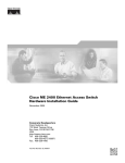
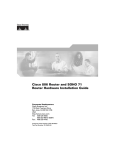
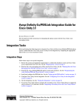
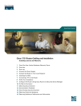
Integration Description
The QSIG/DPNSS integration uses a Cisco EGW 2200, which translates QSIG or DPNSS call signaling
into SIP, a VoIP gateway, and the LAN to connect Cisco Unity Connection and a QSIG/DPNSS phone
system. Figure 1 shows the required connections.
QSIG/DPNSS Phone System with Cisco EGW 2200 Integration Guide for Cisco Unity Connection 1.1
2
OL-8187-01
QSIG/DPNSS Phone System with Cisco EGW 2200 Integration Guide for Cisco Unity Connection 1.1
Integration Description
Figure 1
Connections Between a QSIG/DPNSS Phone System and Cisco Unity Connection
Cisco EGW 2200
Cisco Unity
Connection server
VoIP
gateway
QSIG/DPNSS
phone system
QSIG or DPNSS
connection
LAN
V
C
SIP signaling path
RTP (voice) path
132956
QSIG or DPNSS signaling backhaul path
Call Information
The QSIG/DPNSS integration sends the following information with forwarded calls:
•
The extension of the called party
•
The extension of the calling party (for internal calls) or the phone number of the calling party (if it
is an external call and the system uses caller ID)
•
The reason for the forward (the extension is busy, does not answer, or is set to forward all calls)
Cisco Unity Connection uses this information to answer the call appropriately. For example, a call
forwarded to Cisco Unity Connection is answered with the personal greeting of the user. If the phone
system routes the call to Cisco Unity Connection without this information, Cisco Unity Connection
answers with the opening greeting.
Integration Features
The QSIG/DPNSS integration with Cisco Unity Connection provides the following features.
Call forward to personal greeting
When an incoming call is routed to an unanswered extension, the
call is forwarded to the voice mail of the user. The caller then hears
the personal greeting of the user and can leave a message.
Call forward to busy greeting
When an incoming call is routed to a busy extension, the call is
forwarded to the voice mail of the user. The caller then hears the
busy greeting (if the user enabled it) and can leave a message.
Caller ID
Cisco Unity Connection receives caller ID information from the
phone system (if available). This information appears in the subject
line of the message in the desktop messaging application.
Easy message access
A user can retrieve messages without entering an ID. Cisco Unity
Connection identifies a user based on the extension from which the
call originated. A password may be required.
QSIG/DPNSS Phone System with Cisco EGW 2200 Integration Guide for Cisco Unity Connection 1.1
OL-8187-01
3
QSIG/DPNSS Phone System with Cisco EGW 2200 Integration Guide for Cisco Unity Connection 1.1
Planning How the Voice Messaging Ports Will Be Used by Cisco Unity Connection
Identified user messaging
Cisco Unity Connection automatically identifies a user who leaves
a message during a forwarded internal call, based on the extension
from which the call originated.
Message waiting indication
When a message is waiting for a user, Cisco Unity Connection
notifies the phone system to activate the message waiting indicator
(MWI) on the user extension.
Integrations with Multiple Phone Systems
Cisco Unity Connection can be integrated with multiple phone systems at one time. For the most recent
information on and instructions for integrating Cisco Unity Connection with multiple phone systems,
refer to the Multiple Phone System Integration Guide at
http://www.cisco.com/en/US/products/ps6509/products_installation_and_configuration_guides_list.ht
ml.
Planning How the Voice Messaging Ports Will Be Used by
Cisco Unity Connection
Before programming the phone system, you need to plan how the voice messaging ports will be used by
Cisco Unity Connection.
Unlike other integrations, the hunt group mechanism for a QSIG/DPNSS phone system integration is
implemented on the Cisco Unity Connection server. Within a port group, each incoming call hunts for
an available voice messaging port among all the ports in a round-robin (or circular) fashion. If a voice
messaging port in the cluster is set not to answer calls or is not enabled, a call reaching that port may
receive a busy signal.
Table 1 describes the voice messaging port settings in Cisco Unity Connection that can be set on
Telephony Integrations > Port of Cisco Unity Connection Administration.
Table 1
Settings for the Voice Messaging Ports
Field
Considerations
Enabled
Check this check box.
Answer Calls
Check this check box.
Caution
All voice messaging ports connecting to the phone system must have the
Answer Calls box checked. Otherwise, calls to Cisco Unity Connection may
not be answered.
Perform Message Notification
Check this check box to designate the port for notifying users of messages.
Send MWI Requests
Check this check box to designate the port for turning MWIs on and off.
Allow TRAP Connections
Check this check box so that users can use the phone as a recording and playback device
in Cisco Unity Connection web applications and e-mail clients.
The Number of Voice Messaging Ports to Install
The number of voice messaging ports to install depends on numerous factors, including:
QSIG/DPNSS Phone System with Cisco EGW 2200 Integration Guide for Cisco Unity Connection 1.1
4
OL-8187-01
QSIG/DPNSS Phone System with Cisco EGW 2200 Integration Guide for Cisco Unity Connection 1.1
Programming the QSIG/DPNSS Phone System
•
The number of calls Cisco Unity Connection will answer when call traffic is at its peak.
•
The expected length of each message that callers will record and that users will listen to.
•
The number of users.
•
The number of calls made for message notification.
•
The number of MWIs that will be activated when call traffic is at its peak.
•
The number of TRAP connections needed when call traffic is at its peak. (TRAP connections are
used by Cisco Unity Connection web applications and e-mail clients to play back and record over
the phone.)
•
The number of calls that will use the automated attendant and call handlers when call traffic is at its
peak.
It is best to install only the number of voice messaging ports that are needed so that system resources are
not allocated to unused ports.
The Number of Voice Messaging Ports That Will Answer Calls
The calls that the voice messaging ports answer can be incoming calls from unidentified callers or from
users. Assign all of the voice messaging ports to answer calls.
You can set voice messaging ports to both answer calls and to dial out (for example, to set MWIs).
The Number of Voice Messaging Ports That Will Dial Out
Ports that will dial out can do one or more of the following:
•
Notify users by phone, pager, or e-mail of messages that have arrived.
•
Turn MWIs on and off for user extensions.
•
Make a TRAP connection so that users can use the phone as a recording and playback device in
Cisco Unity Connection web applications and e-mail clients.
Preparing for Programming the Phone System
Record your decisions about the voice messaging ports to guide you in programming the phone system.
Programming the QSIG/DPNSS Phone System
For information on provisioning a QSIG or DPNSS phone system to integrate with Cisco Unity
Connection, refer to the Cisco EGW 2200 documentation.
Caution
In programming the phone system, do not send calls to voice messaging ports in Cisco Unity Connection
that cannot answer calls (voice messaging ports that are not set to Answer Calls). For example, if a voice
messaging port is set only to Dialout MWI, do not send calls to it.
Note
You can use alternate extensions to create multiple line appearances, enable easy message access from
cell phones, and simplify addressing messages to users at different locations in Cisco Unity Connection.
Enabling alternate MWIs lets Cisco Unity Connection turn MWIs on at more than one extension. For
details, see the “Appendix: Using Alternate Extensions and MWIs” section on page 15.
QSIG/DPNSS Phone System with Cisco EGW 2200 Integration Guide for Cisco Unity Connection 1.1
OL-8187-01
5
QSIG/DPNSS Phone System with Cisco EGW 2200 Integration Guide for Cisco Unity Connection 1.1
Setting Up the Cisco EGW 2200
Setting Up the Cisco EGW 2200
For information on setting up the Cisco EGW 2200, refer to the Cisco EGW 2200 documentation.
Creating a New Integration with the QSIG/DPNSS Phone System
After ensuring that the QSIG/DPNSS phone system and Cisco Unity Connection are ready for the
integration, do the following procedures to set up the integration and to enter the port settings.
To Create an Integration
Step 1
Log on to Cisco Unity Connection Administration.
Step 2
In Cisco Unity Connection Administration, expand Telephony Integrations, then click Phone System.
Step 3
On the Search Phone Systems page, on the Phone System menu, click New Phone System. The Phone
System Integration Wizard appears.
Step 4
On the Select Phone System Manufacturer page, in the Manufacturer field, click QSIG/DPNSS and click
Next.
Step 5
On the Select Phone System Model page, in the Model field, click QSIG/DPNSS and click Next.
Step 6
On the Set Up Phone System page, in the Phone System Name field, accept the default name or enter the
descriptive name that you want, and click Next.
Step 7
On the Select Port Group Template page, in the Port Group Template field, click QSIG/DPNSS PBX
via Cisco EGW 2200 and click Next.
Step 8
On the Set Up Port Group page, enter the following settings and click Next.
Table 2
Settings for the Set Up Port Group Page
Field
Setting
Port Group Name
<a descriptive name for the port group; accept the default name or enter the
name that you want>
Contact Line Name
<the voice messaging pilot number that matches the Cisco EGW 2200 dial
plan configuration>
Authenticate with SIP
Proxy Server
If you do not use a SIP proxy server, uncheck the check box.
Authentication User
Name
<the name that Cisco Unity Connection will use to authenticate with the
SIP proxy server>
If you use a SIP proxy server, indicate whether you want Cisco Unity
Connection to authenticate with the SIP proxy server.
Authentication Password <the password that Cisco Unity Connection will use to authenticate with
the SIP proxy server>
Number of Ports
<the number of voice messaging ports that you want to create in this port
group>
IP Address or Host Name <the IP address (or host name) of the primary Cisco EGW 2200 or SIP
proxy server that you are connection to Cisco Unity Connection>
QSIG/DPNSS Phone System with Cisco EGW 2200 Integration Guide for Cisco Unity Connection 1.1
6
OL-8187-01
QSIG/DPNSS Phone System with Cisco EGW 2200 Integration Guide for Cisco Unity Connection 1.1
Creating a New Integration with the QSIG/DPNSS Phone System
Table 2
Settings for the Set Up Port Group Page (continued)
Field
Setting
Test Address
Click this button to verify the IP address (or host name) that you entered.
The result of the test appears in the text box beside the button.
Port
<the IP port of the primary Cisco EGW 2200 or SIP proxy server that you
are connecting to Cisco Unity Connection; we recommend that you use the
default setting>
Caution
This setting must match the port setting of the Cisco EGW 2200
or SIP proxy server. Otherwise the integration will not function
correctly.
Step 9
On the Confirm Phone System Settings page, confirm the settings that you have entered and click Finish.
Step 10
On the Phone System Creation Summary page, click Close.
Step 11
In Cisco Unity Connection Administration, expand Telephony Integrations, then click Port Group.
Step 12
On the Search Port Groups page, click the display name of the port group that you created for the
QSIG/DPNSS integration.
By default, the display name for a port group is composed of the phone system display name
followed by an incrementing number.
Note
Step 13
On the Port Group Basics page, on the Edit menu, click Servers.
Step 14
On the Edit Servers page, do the following substeps if there is a secondary Cisco EGW 2220 or SIP
proxy server. Otherwise, continue to Step 15.
a.
Under SIP Proxy Servers, click Add.
b.
Enter the following settings for the secondary Cisco EGW 2220 or SIP proxy server and click Save.
Table 3
Settings for the Cisco EGW 2220 or SIP Proxy Server
Field
Setting
Order
<the order of priority for the Cisco EGW 2220 or SIP proxy server; the lowest
number is the primary Cisco EGW 2220 or SIP proxy server, the higher
numbers are the secondary servers>
IP Address or Host
Name
<the IP address (or host name) of the secondary Cisco EGW 2220 or SIP proxy
server>
Port
<the IP port of the secondary Cisco EGW 2220 or SIP proxy server that you
are integrating with Cisco Unity Connection; we recommend that you use the
default setting>
Note
You can click Ping to verify the IP address (or host name) of the Cisco EGW 2220 or SIP proxy
server.
QSIG/DPNSS Phone System with Cisco EGW 2200 Integration Guide for Cisco Unity Connection 1.1
OL-8187-01
7
QSIG/DPNSS Phone System with Cisco EGW 2200 Integration Guide for Cisco Unity Connection 1.1
Creating a New Integration with the QSIG/DPNSS Phone System
c.
Repeat Step 14a. and Step 14b. for any remaining secondary Cisco EGW 2220 or SIP proxy server
in the cluster.
Step 15
In Cisco Unity Connection Administration, expand Telephony Integrations, then click Port.
Step 16
On the Search Ports page, click the display name of the first voice messaging port that you created for
this phone system integration.
Note
Step 17
Table 4
By default, the display names for the voice messaging ports are composed of the port group
display name followed by incrementing numbers.
On the Port Basics page, enter the following settings. The fields in the following table are the ones that
you can change.
Settings for the Voice Messaging Ports
Field
Considerations
Enabled
Check this check box.
Answer Calls
Check this check box.
Caution
All voice messaging ports connecting to the phone system must have the
Answer Calls box checked. Otherwise, calls to Cisco Unity Connection may
not be answered.
Perform Message Notification
Check this check box to designate the port for notifying users of messages.
Send MWI Requests
Check this check box to designate the port for turning MWIs on and off.
Allow TRAP Connections
Check this check box so that users can use the phone as a recording and playback device
in Cisco Unity Connection web applications and e-mail clients.
Step 18
Click Save.
Step 19
Click Next.
Step 20
Repeat Step 17 through Step 19 for all remaining voice messaging ports for the phone system.
Step 21
If another phone system integration exists, in Cisco Unity Connection Administration, expand
Telephony Integrations, then click Trunk. Otherwise, skip to Step 25.
Step 22
On the Search Phone System Trunks page, on the Phone System Trunk menu, click New Phone System
Trunk.
Step 23
On the New Phone System Trunk page, enter the following settings for the phone system trunk and click
Save.
Table 5
Settings for the Phone System Trunk
Field
Setting
From Phone System
<the display name of the phone system that you are creating a trunk for>
To Phone System
<the display name of the previously existing phone system that the trunk will
connect to>
Trunk Access Code
<the extra digits that Cisco Unity Connection must dial to transfer calls
through the gateway to extensions on the previously existing phone system>
QSIG/DPNSS Phone System with Cisco EGW 2200 Integration Guide for Cisco Unity Connection 1.1
8
OL-8187-01
QSIG/DPNSS Phone System with Cisco EGW 2200 Integration Guide for Cisco Unity Connection 1.1
Testing the Integration
Step 24
Repeat Step 22 and Step 23 for all remaining phone system trunks that you want to create.
Step 25
If prompted to restart Cisco Unity Connection, in the Windows task bar, right-click the Cisco Unity
Connection icon and click Restart > Voice Processing Server Role.
Step 26
When prompted to confirm stopping the Voice Processing server role, click Yes.
Step 27
In Cisco Unity Connection Administration, in the Related Links drop-down list, click Check Telephony
Configuration and click Go to confirm the phone system integration settings.
If the test is not successful, the Task Execution Results displays one or more messages with
troubleshooting steps. After correcting the problems, test the connection again.
Step 28
In the Task Execution Results window, click Close.
Step 29
Log off Cisco Unity Connection Administration.
Testing the Integration
To test whether Cisco Unity Connection and the phone system are integrated correctly, do the following
procedures in the order listed.
If any of the steps indicate a failure, refer to the following documentation as applicable:
•
The installation guide for the phone system.
•
The setup information earlier in this guide.
To Set Up the Test Configuration
Step 1
Set up two test extensions (Phone 1 and Phone 2) on the same phone system that Cisco Unity Connection
is connected to.
Step 2
Set Phone 1 to forward calls to the Cisco Unity Connection pilot number when calls are not answered.
Caution
The phone system must forward calls to the Cisco Unity Connection pilot number in no fewer
than four rings. Otherwise, the test may fail.
Step 3
To create a test user for testing, in Cisco Unity Connection Administration, click Users.
Step 4
On the Search Users page, on the User menu, click New User.
Step 5
On the New User page, enter the following settings.
Table 6
Settings for the New User Page
Field
Setting
User Type
User with Voice Mailbox
User Template
<the applicable user template>
Alias
testuser
First Name
Test
Last Name
User
QSIG/DPNSS Phone System with Cisco EGW 2200 Integration Guide for Cisco Unity Connection 1.1
OL-8187-01
9
QSIG/DPNSS Phone System with Cisco EGW 2200 Integration Guide for Cisco Unity Connection 1.1
Testing the Integration
Table 6
Settings for the New User Page (continued)
Field
Setting
Display Name
Test User
Extension
<the extension of Phone 1>
Step 6
Click Save.
Step 7
On the User Basics page, in the Voice Name field, record a voice name for the test user.
Step 8
In the Phone System field, confirm that the phone system selected is the phone system that Phone 1 is
connected to.
Step 9
Uncheck the Set for Self-enrollment at Next Login check box.
Step 10
Click Save.
Step 11
On the Edit menu, click Message Waiting Indicators.
Step 12
On the Message Waiting Indicators page, click the message waiting indicator. If no message waiting
indication is in the table, click Add New.
Step 13
On the Edit Message Waiting Indicator page, enter the following settings.
Table 7
Settings for the Edit MWI Page
Field
Setting
Enabled
Check this check box to enable MWIs for the test user.
Display Name
Accept the default or enter a different name.
Inherit User’s
Extension
Check this check box to enable MWIs on Phone 1.
Extension
<the extension of Phone 1>
Phone System
<the phone system that Phone 1 is connected to>
Step 14
Click Save.
Step 15
On the Edit menu, click Transfer Options.
Step 16
On the Edit Transfer Option page, under Call Transfer, click the Extension option and enter the
extension of Phone 1.
Step 17
In the Transfer Type field, click Release to Switch.
Step 18
Click Save.
Step 19
Minimize the Cisco Unity Connection Administration window.
Do not close the Cisco Unity Connection Administration window because you will use it again in a later
procedure.
Step 20
On the Cisco Unity Connection desktop, double-click the Tools Depot icon.
Step 21
In the left pane of the Tools Depot window, expand Switch Integration Tools, then double-click Port
Status Monitor. The Port Status Monitor window appears.
Step 22
On the Ports menu, click Start All, and arrange the port monitors so that you can notice which port will
handle the calls that you will make.
QSIG/DPNSS Phone System with Cisco EGW 2200 Integration Guide for Cisco Unity Connection 1.1
10
OL-8187-01
QSIG/DPNSS Phone System with Cisco EGW 2200 Integration Guide for Cisco Unity Connection 1.1
Testing the Integration
To Test an External Call with Release Transfer
Step 1
From Phone 2, enter the access code necessary to get an outside line, then enter the number outside
callers use to dial directly to Cisco Unity Connection.
Step 2
In the Port Status Monitor, note which port handles this call.
Step 3
When you hear the opening greeting, enter the extension for Phone 1. Hearing the opening greeting
means that the port is configured correctly.
Step 4
Confirm that Phone 1 rings and that you hear a ringback tone on Phone 2. Hearing a ringback tone means
that Cisco Unity Connection correctly released the call and transferred it to Phone 1.
Step 5
Leaving Phone 1 unanswered, confirm that the state of the port handling the call changes to “Idle.” This
state means that release transfer is successful.
Step 6
Confirm that, after the number of rings that the phone system is set to wait, the call is forwarded to
Cisco Unity Connection and that you hear the greeting for the test user. Hearing the greeting means that
the phone system forwarded the unanswered call and the call-forward information to Cisco Unity
Connection, which correctly interpreted the information.
Step 7
On the Port Status Monitor, note which port handles this call.
Step 8
Leave a message for the test user and hang up Phone 2.
Step 9
In the Port Status Monitor, confirm that the state of the port handling the call changes to “Idle.” This
state means that the port was successfully released when the call ended.
Step 10
Confirm that the MWI on Phone 1 is activated. The activated MWI means that the phone system and
Cisco Unity Connection are successfully integrated for turning on MWIs.
To Test Listening to Messages
Step 1
From Phone 1, enter the internal pilot number for Cisco Unity Connection.
Step 2
When asked for your password, enter the password for the test user. Hearing the request for your
password means that the phone system sent the necessary call information to Cisco Unity Connection,
which correctly interpreted the information.
Step 3
Confirm that you hear the recorded voice name for the test user (if you did not record a voice name for
the test user, you will hear the extension number for Phone 1). Hearing the voice name means that
Cisco Unity Connection correctly identified the user by the extension.
Step 4
Listen to the message.
Step 5
After listening to the message, delete the message.
Step 6
Confirm that the MWI on Phone 1 is deactivated. The deactivated MWI means that the phone system and
Cisco Unity Connection are successfully integrated for turning off MWIs.
Step 7
Hang up Phone 1.
Step 8
On the Port Status Monitor, confirm that the state of the port handling the call changes to “Idle.” This
state means that the port was successfully released when the call ended.
QSIG/DPNSS Phone System with Cisco EGW 2200 Integration Guide for Cisco Unity Connection 1.1
OL-8187-01
11
QSIG/DPNSS Phone System with Cisco EGW 2200 Integration Guide for Cisco Unity Connection 1.1
Testing the Integration
To Set Up Supervised Transfer on Cisco Unity Connection
Step 1
In Cisco Unity Connection Administration, on the Edit Transfer Option page for the test user, in the
Transfer Type field, click Supervise Transfer.
Step 2
In the Rings to Wait For field, enter 3.
Step 3
Click Save.
Step 4
Minimize the Cisco Unity Connection Administration window.
Do not close the Cisco Unity Connection Administration window because you will use it again in a later
procedure.
To Test Supervised Transfer
Step 1
From Phone 2, enter the access code necessary to get an outside line, then enter the number outside
callers use to dial directly to Cisco Unity Connection.
Step 2
On the Port Status Monitor, note which port handles this call.
Step 3
When you hear the opening greeting, enter the extension for Phone 1. Hearing the opening greeting
means that the port is configured correctly.
Step 4
Confirm that Phone 1 rings and that you do not hear a ringback tone on Phone 2. Instead, you should
hear the indication your phone system uses to mean that the call is on hold (for example, music).
Step 5
Leaving Phone 1 unanswered, confirm that the state of the port handling the call remains “Busy.” This
state and hearing an indication that you are on hold mean that Cisco Unity Connection is supervising the
transfer.
Step 6
Confirm that, after three rings, you hear the greeting for the test user. Hearing the greeting means that
Cisco Unity Connection successfully recalled the supervised-transfer call.
Step 7
During the greeting, hang up Phone 2.
Step 8
On the Port Status Monitor, confirm that the state of the port handling the call changes to “Idle.” This
state means that the port was successfully released when the call ended.
Step 9
Exit the Port Status Monitor.
To Delete the Test User
Step 1
In Cisco Unity Connection Administration, click Users.
Step 2
On the Search Users page, check the check box to the left of the test user.
Step 3
Click Delete Selected.
QSIG/DPNSS Phone System with Cisco EGW 2200 Integration Guide for Cisco Unity Connection 1.1
12
OL-8187-01
QSIG/DPNSS Phone System with Cisco EGW 2200 Integration Guide for Cisco Unity Connection 1.1
(Multiple Integrations Only) Adding New User Templates
(Multiple Integrations Only) Adding New User Templates
When you create the first phone system integration, this phone system is automatically selected in the
default user template. The users that you add after creating this phone system integration will be assigned
to this phone system by default.
However, for each additional phone system integration that you create, you must add the applicable new
user templates that will assign users to the new phone system. You must add the new templates before
you add new users who will be assigned to the new phone system.
For details on adding new user templates, refer to the “Adding, Changing, or Deleting an Account
Template” chapter in the Cisco Unity Connection User Moves, Adds, and Changes Guide at
http://www.cisco.com/en/US/products/ps6509/prod_maintenance_guides_list.html.
For details on selecting a user template when adding a new user, refer to the applicable chapter for adding
user accounts in the Cisco Unity Connection User Moves, Adds, and Changes Guide at
http://www.cisco.com/en/US/products/ps6509/prod_maintenance_guides_list.html.
Changing the Settings for an Existing Integration
After the integration is set up, if you want to change any of its settings (for example, to add or remove
voice messaging ports for an integration), do the following procedure.
To Change the Settings for an Integration
Step 1
Log on to Cisco Unity Connection Administration.
Step 2
In Cisco Unity Connection Administration, expand Telephony Integrations.
Step 3
Click the applicable location:
•
Phone System
•
Port Group
•
Port
Step 4
On the Search page, click the phone system, port group, or port for which you want to change settings.
Step 5
Enter new settings in the fields that you want to change.
Caution
If you are adding or removing voice messaging ports, make sure you change the settings for
the individual ports so that there are an appropriate number of ports set to answer calls and an
appropriate number of ports set to dial out.
Step 6
Click Save.
Step 7
If prompted to restart Cisco Unity Connection, in the Windows task bar, right-click the Cisco Unity
Connection icon and click Restart > Voice Processing Server Role.
Step 8
When prompted to confirm stopping the Voice Processing server role, click Yes.
Step 9
In Cisco Unity Connection Administration, in the Related Links drop-down list, click Check Telephony
Configuration and click Go to confirm the phone system integration settings.
If the test is not successful, the Task Execution Results displays one or more messages with
troubleshooting steps. After correcting the problems, test the connection again.
QSIG/DPNSS Phone System with Cisco EGW 2200 Integration Guide for Cisco Unity Connection 1.1
OL-8187-01
13
QSIG/DPNSS Phone System with Cisco EGW 2200 Integration Guide for Cisco Unity Connection 1.1
Deleting an Existing Phone System Integration
Step 10
In the Task Execution Results window, click Close.
Step 11
Log off Cisco Unity Connection Administration.
Deleting an Existing Phone System Integration
If you want to delete an existing phone system integration (for example, you have replaced the phone
system with which Cisco Unity Connection originally integrated), confirm that the following items are
deleted or associated to another phone system:
•
Users (including MWI devices and notification devices) who are associated with the phone system
that you want to delete.
To see a list of users associated with the phone system, in Cisco Unity Connection Administration,
expand Telephony Integrations > Phone System; click the name of the phone system; on the Phone
System Basics page, on the Edit menu, click Phone System Associations.
•
User templates that are associated with the phone system that you want to delete.
•
System call handlers that are associated with the phone system that you want to delete.
•
Call handler templates that are associated with the phone system that you want to delete.
If users, user templates, call handlers, MWI devices, or notification devices are associated with this
phone system, Cisco Unity Connection cannot delete the phone system.
When you attempt to delete a phone system that still has these items associated with it, a status warning
will appear with a link to the Delete Phone System Wizard. This wizard will guide you to associate all
items from the phone system that you want to delete to another phone system.
All users, user templates, call handlers, MWI devices and notification devices that are associated with a
phone system must be reassigned before the phone system can be deleted.
Note
You can see a list of users who are associated with a phone system on the Phone System Associations
page for the phone system. To view Phone System Associations page, on the Phone System Basics page,
click Phone System Associations on the Edit menu.
It is not necessary to delete the port groups or ports that belong to a phone system before deleting the
phone system integration. The member port groups and ports will be automatically deleted with the
phone system.
Note
Port groups and ports that do not belong to the phone system will not be affected when the phone system
integration is deleted.
Do the following procedure.
To Delete an Existing Phone System Integration
Step 1
Log on to Cisco Unity Connection Administration.
Step 2
In Cisco Unity Connection Administration, expand Telephony Integrations, then click Phone System.
QSIG/DPNSS Phone System with Cisco EGW 2200 Integration Guide for Cisco Unity Connection 1.1
14
OL-8187-01
Appendix: Using Alternate Extensions and MWIs
Alternate Extensions
Step 3
On the Search Phone Systems page, check the check box to the left of the phone system that you want
to delete.
Step 4
Click Delete Selected.
Step 5
When prompted to confirm that you want to delete the phone system, click OK.
Step 6
If prompted to restart Cisco Unity Connection, in the Windows task bar, right-click the Cisco Unity
Connection icon and click Restart > Voice Processing Server Role.
Step 7
When prompted to confirm stopping the Voice Processing server role, click Yes.
Step 8
Log off Cisco Unity Connection Administration.
Appendix: Using Alternate Extensions and MWIs
Alternate Extensions
On the New Phone Number page for a user, you can assign up to nine alternate extensions for the user.
(The primary extension is the one that you assign to each user when the user is added to Cisco Unity
Connection.)
Reasons to Use Alternate Extensions
There are several reasons that you may want to specify alternate extensions for users. For example, if
you have more than one Cisco Unity Connection server that accesses a single, corporate-wide directory,
you may want to use alternate extensions to simplify addressing messages to users at the different
locations. With alternate extensions, the number that a user enters when addressing a message to
someone at another location can be the same number that the user dials when calling. You may also want
to use alternate extensions to:
•
Handle multiple line appearances on user phones.
•
Offer easy message access on direct calls from a cell phone, home phone, or phone at an alternate
work site (assuming that the phone number is passed along to Cisco Unity Connection from these
other phone systems). In addition, when such phones are used as alternate extensions, and are set to
forward to Cisco Unity Connection, callers can listen to the user greeting and leave messages for the
user just as they would when dialing the primary extension for the user.
•
Enable URL-based extensions in Cisco Unity Connection for an integration with a SIP phone
system.
How Alternate Extensions Work
Before you set up alternate extensions, review the following list for information on how alternate
extensions work:
•
Alternate extensions cannot exceed 30 characters in length. By default, each administrator-defined
alternate extension must be at least 3 characters in length, while user-defined alternate extensions
must be at least 10 characters.
QSIG/DPNSS Phone System with Cisco EGW 2200 Integration Guide for Cisco Unity Connection 1.1
OL-8187-01
15
Appendix: Using Alternate Extensions and MWIs
Alternate Extensions
•
Cisco Unity Connection Administration will not accept an extension that is already assigned to
another user (either as a primary or alternate extension), or to a public distribution list, call handler,
directory handler, or interview handler. Cisco Unity Connection verifies that each alternate
extension is unique—up to the dialing domain level, if applicable—before allowing either an
administrator or a user to create it.
•
All alternate extensions use the same transfer settings as the primary extension.
•
In many cases, Cisco Unity Connection can activate a message waiting indicator (MWI) for an
alternate extension. However, depending on the phones and phone systems involved, some
additional phone system programming may be required to set this up.
Setting Up Alternate Extensions
Do the applicable procedure to add, modify, or delete alternate extensions:
•
To Add Administrator-Defined Alternate Extensions, page 16
•
To Modify Alternate Extensions, page 17
•
To Delete Alternate Extensions, page 17
To Add Administrator-Defined Alternate Extensions
Step 1
In Cisco Unity Connection Administration, click User.
Step 2
On the Search Users page, click the user for whom you want to add an alternate extension.
Step 3
On the Edit menu, click Phone Numbers.
Step 4
On the Phone Numbers page, click Add New.
Step 5
On the New Phone Number page, enter the following settings.
Table 8
Settings for the New Phone Number Page
Field
Setting
Phone Type
Click the type of phone that will use the extension.
Display Name
Enter a description of the extension.
Phone Number
Enter the extension. When entering characters, consider the following:
•
You can enter an extension up to 30 characters in length. (SIP integrations
can use up to 30 alphanumeric characters.)
•
Each extension must be unique—up to the dialing domain level, if
applicable.
•
Enter digits 0 through 9. Do not use spaces, dashes, or parentheses.
Step 6
Click Save.
Step 7
Repeat Step 3 through Step 6 as necessary.
QSIG/DPNSS Phone System with Cisco EGW 2200 Integration Guide for Cisco Unity Connection 1.1
16
OL-8187-01
Appendix: Using Alternate Extensions and MWIs
Alternate MWIs
To Modify Alternate Extensions
Step 1
In Cisco Unity Connection Administration, click User.
Step 2
On the Search Users page, click the user for whom you want to modify an alternate extension.
Step 3
On the Edit menu, click Phone Numbers.
Step 4
On the Phone Numbers page, click the alternate extension that you want to change.
Step 5
On the Phone Number page, in the Phone Number field, change the extension and click Save.
Step 6
Repeat Step 3 through Step 5 as necessary.
To Delete Alternate Extensions
Step 1
In Cisco Unity Connection Administration, click User.
Step 2
On the Search Users page, click the user for whom you want to delete an alternate extension.
Step 3
On the Edit menu, click Phone Numbers.
Step 4
On the Phone Numbers page, check the check box next to the extensions that you want to delete.
Step 5
Click Delete Selected.
Alternate MWIs
You can set up Cisco Unity Connection to activate alternate MWIs when you want a new message for a
user to activate the MWIs at up to 10 extensions. For example, a message left at extension 1001 can
activate the MWIs on extensions 1001 and 1002.
Cisco Unity Connection uses MWIs to alert the user to new voice messages. MWIs are not used to
indicate new e-mail, fax, or return receipt messages.
Setting Up Alternate MWIs
Cisco Unity Connection can activate alternate MWIs. Note that depending on the phones and phone
systems, some additional phone system programming may be necessary. Refer to the installation guide
for the phone system.
Do the applicable procedure to add, modify, or delete alternate MWIs:
•
To Add Alternate MWIs for Extensions, page 17
•
To Modify Alternate MWIs, page 18
•
To Delete Alternate MWIs, page 19
To Add Alternate MWIs for Extensions
Step 1
In Cisco Unity Connection Administration, click User.
Step 2
On the Search Users page, click the user for whom you want to add an alternate MWI.
QSIG/DPNSS Phone System with Cisco EGW 2200 Integration Guide for Cisco Unity Connection 1.1
OL-8187-01
17
Appendix: Using Alternate Extensions and MWIs
Alternate MWIs
Step 3
On the Edit menu, click Message Waiting Indicators.
Step 4
On the Message Waiting Indicators page, click Add New.
Step 5
Enter the following settings.
Table 9
Settings for the New Message Waiting Indicator Page
Field
Setting
Enabled
Check the check box.
Display Name
Enter a description of the MWI.
Extension
Enter the extension for the MWI. When entering characters, consider the
following:
•
Enter digits 0 through 9. Do not use spaces, dashes, or parentheses.
•
Enter , (comma) to insert a one-second pause.
•
Enter # and * to correspond to the # and * keys on the phone.
Phone System
Click the name of the phone system that the extension is assigned to.
Current Status
(Display only) The indication whether the MWI is currently on or off.
Step 6
Click Save.
Step 7
Repeat Step 3 through Step 6 as necessary.
To Modify Alternate MWIs
Step 1
In Cisco Unity Connection Administration, click User.
Step 2
On the Search Users page, click the user for whom you want to change an alternate MWI.
Step 3
On the Edit menu, click Message Waiting Indicators.
Step 4
On the Message Waiting Indicators page, click the MWI that you want to change.
Step 5
On the Edit Message Waiting Indicator page, change the applicable settings.
Table 10
Settings for the New Message Waiting Indicator Page
Field
Setting
Enabled
Check or uncheck the check box as applicable.
Display Name
Revise the description of the MWI.
Extension
Revise the extension for the MWI. When entering characters, consider the
following:
•
Enter digits 0 through 9. Do not use spaces, dashes, or parentheses.
•
Enter , (comma) to insert a one-second pause.
•
Enter # and * to correspond to the # and * keys on the phone.
Phone System
Click the name of the phone system that the extension is assigned to.
Current Status
(Display only) The indication whether the MWI is currently on or off.
QSIG/DPNSS Phone System with Cisco EGW 2200 Integration Guide for Cisco Unity Connection 1.1
18
OL-8187-01
Appendix: Documentation and Technical Assistance
Conventions
Step 6
Click Save.
Step 7
Repeat Step 3 through Step 6 as necessary.
To Delete Alternate MWIs
Step 1
In Cisco Unity Connection Administration, click User.
Step 2
On the Search Users page, click the user for whom you want to delete an alternate MWI.
Step 3
On the Edit menu, click Message Waiting Indicators.
Step 4
On the Message Waiting Indicators page, check the check boxes next to the MWIs that you want to
delete.
Step 5
Click Delete Selected.
Appendix: Documentation and Technical
Assistance
Conventions
The QSIG/DPNSS Phone System with Cisco EGW 2200 Integration Guide for Cisco Unity Connection
1.1 uses the following conventions.
Table 11
QSIG/DPNSS Phone System with Cisco EGW 2200 Integration Guide for
Cisco Unity Connection 1.1 Conventions
Convention
Description
boldfaced text
Boldfaced text is used for:
<>
(angle brackets)
(hyphen)
•
Key and button names. (Example: Click OK.)
•
Information that you enter. (Example: Enter Administrator in the User
Name box.)
Angle brackets are used around parameters for which you supply a value.
(Example: In the Command Prompt window, enter ping <IP address>.)
Hyphens separate keys that must be pressed simultaneously. (Example: Press
Ctrl-Alt-Delete.)
QSIG/DPNSS Phone System with Cisco EGW 2200 Integration Guide for Cisco Unity Connection 1.1
OL-8187-01
19
Appendix: Documentation and Technical Assistance
Obtaining Documentation
Table 11
QSIG/DPNSS Phone System with Cisco EGW 2200 Integration Guide for
Cisco Unity Connection 1.1 Conventions (continued)
Convention
Description
>
A right angle bracket is used to separate selections that you make:
(right angle
bracket)
[x]
(square brackets)
[x | y]
(vertical line)
{x | y}
(braces)
•
On menus. (Example: On the Windows Start menu, click Settings > Control
Panel > Phone and Modem Options.)
•
In the navigation bar of Cisco Unity Connection Administration. (Example:
In Cisco Unity Connection Administration, expand System Settings >
Advanced.)
Square brackets enclose an optional element (keyword or argument). (Example:
[reg-e164])
Square brackets enclosing keywords or arguments separated by a vertical line
indicate an optional choice. (Example: [transport tcp | transport udp])
Braces enclosing keywords or arguments separated by a vertical line indicate a
required choice. (Example: {tcp | udp})
The QSIG/DPNSS Phone System with Cisco EGW 2200 Integration Guide for Cisco Unity Connection
1.1 also uses the following conventions:
Note
Caution
Means reader take note. Notes contain helpful suggestions or references to material not covered in the
document.
Means reader be careful. In this situation, you might do something that could result in equipment
damage or loss of data.
For descriptions and URLs of Cisco Unity Connection documentation on Cisco.com, see the
About Cisco Unity Connection Documentation. The document is shipped with Cisco Unity Connection
and is available at
http://www.cisco.com/en/US/products/ps6509/products_documentation_roadmaps_list.html.
Obtaining Documentation
Cisco documentation and additional literature are available on Cisco.com. Cisco also provides several
ways to obtain technical assistance and other technical resources. These sections explain how to obtain
technical information from Cisco Systems.
Cisco.com
You can access the most current Cisco documentation at this URL:
http://www.cisco.com/techsupport
QSIG/DPNSS Phone System with Cisco EGW 2200 Integration Guide for Cisco Unity Connection 1.1
20
OL-8187-01
Appendix: Documentation and Technical Assistance
Documentation Feedback
You can access the Cisco website at this URL:
http://www.cisco.com
You can access international Cisco websites at this URL:
http://www.cisco.com/public/countries_languages.shtml
Product Documentation DVD
Cisco documentation and additional literature are available in the Product Documentation DVD package,
which may have shipped with your product. The Product Documentation DVD is updated regularly and
may be more current than printed documentation.
The Product Documentation DVD is a comprehensive library of technical product documentation on
portable media. The DVD enables you to access multiple versions of hardware and software installation,
configuration, and command guides for Cisco products and to view technical documentation in HTML.
With the DVD, you have access to the same documentation that is found on the Cisco website without
being connected to the Internet. Certain products also have .pdf versions of the documentation available.
The Product Documentation DVD is available as a single unit or as a subscription. Registered Cisco.com
users (Cisco direct customers) can order a Product Documentation DVD (product number
DOC-DOCDVD=) from Cisco Marketplace at this URL:
http://www.cisco.com/go/marketplace/
Ordering Documentation
Beginning June 30, 2005, registered Cisco.com users may order Cisco documentation at the Product
Documentation Store in the Cisco Marketplace at this URL:
http://www.cisco.com/go/marketplace/
Nonregistered Cisco.com users can order technical documentation from 8:00 a.m. to 5:00 p.m.
(0800 to 1700) PDT by calling 1 866 463-3487 in the United States and Canada, or elsewhere by
calling 011 408 519-5055. You can also order documentation by e-mail at
[email protected] or by fax at 1 408 519-5001 in the United States and Canada,
or elsewhere at 011 408 519-5001.
Documentation Feedback
You can rate and provide feedback about Cisco technical documents by completing the online feedback
form that appears with the technical documents on Cisco.com.
You can send comments about Cisco documentation to [email protected].
You can submit comments by using the response card (if present) behind the front cover of your
document or by writing to the following address:
Cisco Systems
Attn: Customer Document Ordering
170 West Tasman Drive
San Jose, CA 95134-9883
We appreciate your comments.
QSIG/DPNSS Phone System with Cisco EGW 2200 Integration Guide for Cisco Unity Connection 1.1
OL-8187-01
21
Appendix: Documentation and Technical Assistance
Cisco Product Security Overview
Cisco Product Security Overview
Cisco provides a free online Security Vulnerability Policy portal at this URL:
http://www.cisco.com/en/US/products/products_security_vulnerability_policy.html
From this site, you can perform these tasks:
•
Report security vulnerabilities in Cisco products.
•
Obtain assistance with security incidents that involve Cisco products.
•
Register to receive security information from Cisco.
A current list of security advisories and notices for Cisco products is available at this URL:
http://www.cisco.com/go/psirt
If you prefer to see advisories and notices as they are updated in real time, you can access a Product
Security Incident Response Team Really Simple Syndication (PSIRT RSS) feed from this URL:
http://www.cisco.com/en/US/products/products_psirt_rss_feed.html
Reporting Security Problems in Cisco Products
Cisco is committed to delivering secure products. We test our products internally before we release them,
and we strive to correct all vulnerabilities quickly. If you think that you might have identified a
vulnerability in a Cisco product, contact PSIRT:
•
Emergencies — [email protected]
An emergency is either a condition in which a system is under active attack or a condition for which
a severe and urgent security vulnerability should be reported. All other conditions are considered
nonemergencies.
•
Nonemergencies — [email protected]
In an emergency, you can also reach PSIRT by telephone:
Tip
•
1 877 228-7302
•
1 408 525-6532
We encourage you to use Pretty Good Privacy (PGP) or a compatible product to encrypt any sensitive
information that you send to Cisco. PSIRT can work from encrypted information that is compatible with
PGP versions 2.x through 8.x.
Never use a revoked or an expired encryption key. The correct public key to use in your correspondence
with PSIRT is the one linked in the Contact Summary section of the Security Vulnerability Policy page
at this URL:
http://www.cisco.com/en/US/products/products_security_vulnerability_policy.html
The link on this page has the current PGP key ID in use.
QSIG/DPNSS Phone System with Cisco EGW 2200 Integration Guide for Cisco Unity Connection 1.1
22
OL-8187-01
Appendix: Documentation and Technical Assistance
Obtaining Technical Assistance
Obtaining Technical Assistance
Cisco Technical Support provides 24-hour-a-day award-winning technical assistance. The Cisco
Technical Support & Documentation website on Cisco.com features extensive online support resources.
In addition, if you have a valid Cisco service contract, Cisco Technical Assistance Center (TAC)
engineers provide telephone support. If you do not have a valid Cisco service contract, contact your
reseller.
Cisco Technical Support & Documentation Website
The Cisco Technical Support & Documentation website provides online documents and tools for
troubleshooting and resolving technical issues with Cisco products and technologies. The website is
available 24 hours a day, at this URL:
http://www.cisco.com/techsupport
Access to all tools on the Cisco Technical Support & Documentation website requires a Cisco.com user
ID and password. If you have a valid service contract but do not have a user ID or password, you can
register at this URL:
http://tools.cisco.com/RPF/register/register.do
Note
Use the Cisco Product Identification (CPI) tool to locate your product serial number before submitting
a web or phone request for service. You can access the CPI tool from the Cisco Technical Support &
Documentation website by clicking the Tools & Resources link under Documentation & Tools. Choose
Cisco Product Identification Tool from the Alphabetical Index drop-down list, or click the Cisco
Product Identification Tool link under Alerts & RMAs. The CPI tool offers three search options: by
product ID or model name; by tree view; or for certain products, by copying and pasting show command
output. Search results show an illustration of your product with the serial number label location
highlighted. Locate the serial number label on your product and record the information before placing a
service call.
Submitting a Service Request
Using the online TAC Service Request Tool is the fastest way to open S3 and S4 service requests. (S3
and S4 service requests are those in which your network is minimally impaired or for which you require
product information.) After you describe your situation, the TAC Service Request Tool provides
recommended solutions. If your issue is not resolved using the recommended resources, your service
request is assigned to a Cisco engineer. The TAC Service Request Tool is located at this URL:
http://www.cisco.com/techsupport/servicerequest
For S1 or S2 service requests or if you do not have Internet access, contact the Cisco TAC by telephone.
(S1 or S2 service requests are those in which your production network is down or severely degraded.)
Cisco engineers are assigned immediately to S1 and S2 service requests to help keep your business
operations running smoothly.
To open a service request by telephone, use one of the following numbers:
Asia-Pacific: +61 2 8446 7411 (Australia: 1 800 805 227)
EMEA: +32 2 704 55 55
USA: 1 800 553-2447
QSIG/DPNSS Phone System with Cisco EGW 2200 Integration Guide for Cisco Unity Connection 1.1
OL-8187-01
23
Appendix: Documentation and Technical Assistance
Obtaining Additional Publications and Information
For a complete list of Cisco TAC contacts, go to this URL:
http://www.cisco.com/techsupport/contacts
Definitions of Service Request Severity
To ensure that all service requests are reported in a standard format, Cisco has established severity
definitions.
Severity 1 (S1)—Your network is “down,” or there is a critical impact to your business operations. You
and Cisco will commit all necessary resources around the clock to resolve the situation.
Severity 2 (S2)—Operation of an existing network is severely degraded, or significant aspects of your
business operation are negatively affected by inadequate performance of Cisco products. You and Cisco
will commit full-time resources during normal business hours to resolve the situation.
Severity 3 (S3)—Operational performance of your network is impaired, but most business operations
remain functional. You and Cisco will commit resources during normal business hours to restore service
to satisfactory levels.
Severity 4 (S4)—You require information or assistance with Cisco product capabilities, installation, or
configuration. There is little or no effect on your business operations.
Obtaining Additional Publications and Information
Information about Cisco products, technologies, and network solutions is available from various online
and printed sources.
•
Cisco Marketplace provides a variety of Cisco books, reference guides, documentation, and logo
merchandise. Visit Cisco Marketplace, the company store, at this URL:
http://www.cisco.com/go/marketplace/
•
Cisco Press publishes a wide range of general networking, training and certification titles. Both new
and experienced users will benefit from these publications. For current Cisco Press titles and other
information, go to Cisco Press at this URL:
http://www.ciscopress.com
•
Packet magazine is the Cisco Systems technical user magazine for maximizing Internet and
networking investments. Each quarter, Packet delivers coverage of the latest industry trends,
technology breakthroughs, and Cisco products and solutions, as well as network deployment and
troubleshooting tips, configuration examples, customer case studies, certification and training
information, and links to scores of in-depth online resources. You can access Packet magazine at
this URL:
http://www.cisco.com/packet
•
iQ Magazine is the quarterly publication from Cisco Systems designed to help growing companies
learn how they can use technology to increase revenue, streamline their business, and expand
services. The publication identifies the challenges facing these companies and the technologies to
help solve them, using real-world case studies and business strategies to help readers make sound
technology investment decisions. You can access iQ Magazine at this URL:
http://www.cisco.com/go/iqmagazine
or view the digital edition at this URL:
http://ciscoiq.texterity.com/ciscoiq/sample/
QSIG/DPNSS Phone System with Cisco EGW 2200 Integration Guide for Cisco Unity Connection 1.1
24
OL-8187-01
Appendix: Documentation and Technical Assistance
Obtaining Additional Publications and Information
•
Internet Protocol Journal is a quarterly journal published by Cisco Systems for engineering
professionals involved in designing, developing, and operating public and private internets and
intranets. You can access the Internet Protocol Journal at this URL:
http://www.cisco.com/ipj
•
Networking products offered by Cisco Systems, as well as customer support services, can be
obtained at this URL:
http://www.cisco.com/en/US/products/index.html
•
Networking Professionals Connection is an interactive website for networking professionals to share
questions, suggestions, and information about networking products and technologies with Cisco
experts and other networking professionals. Join a discussion at this URL:
http://www.cisco.com/discuss/networking
•
World-class networking training is available from Cisco. You can view current offerings at
this URL:
http://www.cisco.com/en/US/learning/index.html
service mark of Cisco Systems, Inc.; and Access Registrar, Aironet, BPX, Catalyst, CCDA, CCDP, CCIE, CCIP, CCNA, CCNP, CCSP, Cisco, the Cisco
Certified Internetwork Expert logo, Cisco IOS, Cisco Press, Cisco Systems, Cisco Systems Capital, the Cisco Systems logo, Cisco Unity,
Enterprise/Solver, EtherChannel, EtherFast, EtherSwitch, Fast Step, Follow Me Browsing, FormShare, GigaDrive, HomeLink, Internet Quotient, IOS,
iPhone, IP/TV, iQ Expertise, the iQ logo, iQ Net Readiness Scorecard, iQuick Study, LightStream, Linksys, MeetingPlace, MGX, Networking Academy,
Network Registrar, Packet, PIX, ProConnect, ScriptShare, SMARTnet, StackWise, The Fastest Way to Increase Your Internet Quotient, and TransPath are
registered trademarks of Cisco Systems, Inc. and/or its affiliates in the United States and certain other countries.
All other trademarks mentioned in this document or Website are the property of their respective owners. The use of the word partner does not imply a
partnership relationship between Cisco and any other company. (0705R)
© 2005 Cisco Systems, Inc. All rights reserved.
QSIG/DPNSS Phone System with Cisco EGW 2200 Integration Guide for Cisco Unity Connection 1.1
OL-8187-01
25
Appendix: Documentation and Technical Assistance
Obtaining Additional Publications and Information
QSIG/DPNSS Phone System with Cisco EGW 2200 Integration Guide for Cisco Unity Connection 1.1
26
OL-8187-01