1
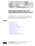
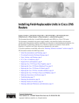
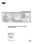
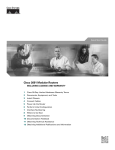
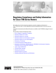
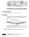
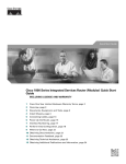
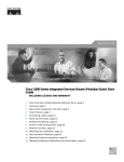
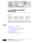
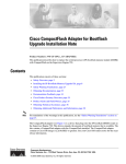
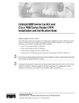
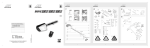
Catalyst 6500 Series 24-Port FXS Analog Interface
Module Installation Note
Product Numbers: WS-X6624-FXS
This publicationdescribes how to install the Catalyst 6500 series 24-port Foreign Exchange Station
(FXS) analog interface module. The FXS interfaces connect directly to standard analog telephones or
fax machines.
Contents
This publication consists of the following sections:
•
Safety Overview, page 2
•
Features, page 5
•
Front Panel Description, page 9
•
Specifications, page 10
•
Installing the 24-Port FXS Analog Interface Module, page 11
•
Connecting a Cable to the 24-Port FXS Analog Interface Module Port, page 15
•
What to Do After Installing the 24-Port FXS Analog Interface Module, page 16
•
Regulatory Standards Compliance, page 17
•
Obtaining Documentation, page 17
•
Obtaining Technical Assistance, page 19
The FXS interfaces supply ring voltage, dial tone, and other services as described in this publication.
FXS ports emulate the central office (CO) or private branch exchange (PBX) in that they provide a
service to an analog telephone or fax machine. The telephone or fax machine behaves as if it is connected
to a normal CO or PBX line.
Note
All signaling configuration is done through Cisco CallManager. Refer to the Cisco CallManager
documentation for complete configuration details.
Corporate Headquarters:
Cisco Systems, Inc., 170 West Tasman Drive, San Jose, CA 95134-1706 USA
Copyright © 2000–2003 Cisco Systems, Inc. All rights reserved.
Safety Overview
Safety Overview
Safety warnings appear throughout this publication in procedures that may harm you if performed
incorrectly. A warning symbol precedes each warning statement.
Note
Warning
For a complete description of safety and compliance requirements, refer to the Regulatory Compliance
and Safety Information for the Calyst 6500 Series Switches document.
IMPORTANT SAFETY INSTRUCTIONS
This warning symbol means danger. You are in a situation that could cause bodily injury. Before you
work on any equipment, be aware of the hazards involved with electrical circuitry and be familiar
with standard practices for preventing accidents. To see translations of the warnings that appear in
this publication, refer to the translated safety warnings that accompanied this device.
Note: SAVE THESE INSTRUCTIONS
Note: This documentation is to be used in conjunction with the specific product installation guide
that shipped with the product. Please refer to the Installation Guide, Configuration Guide, or other
enclosed additional documentation for further details.
Waarschuwing
BELANGRIJKE VEILIGHEIDSINSTRUCTIES
Dit waarschuwingssymbool betekent gevaar. U verkeert in een situatie die lichamelijk letsel kan
veroorzaken. Voordat u aan enige apparatuur gaat werken, dient u zich bewust te zijn van de bij
elektrische schakelingen betrokken risico's en dient u op de hoogte te zijn van de standaard
praktijken om ongelukken te voorkomen. Voor een vertaling van de waarschuwingen die in deze
publicatie verschijnen, dient u de vertaalde veiligheidswaarschuwingen te raadplegen die bij dit
apparaat worden geleverd.
Opmerking BEWAAR DEZE INSTRUCTIES.
Opmerking Deze documentatie dient gebruikt te worden in combinatie met de
installatiehandleiding voor het specifieke product die bij het product wordt geleverd. Raadpleeg de
installatiehandleiding, configuratiehandleiding of andere verdere ingesloten documentatie voor
meer informatie.
Varoitus
TÄRKEITÄ TURVALLISUUTEEN LIITTYVIÄ OHJEITA
Tämä varoitusmerkki merkitsee vaaraa. Olet tilanteessa, joka voi johtaa ruumiinvammaan. Ennen
kuin työskentelet minkään laitteiston parissa, ota selvää sähkökytkentöihin liittyvistä vaaroista ja
tavanomaisista onnettomuuksien ehkäisykeinoista. Tässä asiakirjassa esitettyjen varoitusten
käännökset löydät laitteen mukana toimitetuista ohjeista.
Huomautus SÄILYTÄ NÄMÄ OHJEET
Huomautus Tämä asiakirja on tarkoitettu käytettäväksi yhdessä tuotteen mukana tulleen
asennusoppaan kanssa. Katso lisätietoja asennusoppaasta, kokoonpano-oppaasta ja muista
mukana toimitetuista asiakirjoista.
Catalyst 6500 Series 24-Port FXS Analog Interface Module Installation Note
2
78-10975-02
Safety Overview
Attention
IMPORTANTES INFORMATIONS DE SÉCURITÉ
Ce symbole d'avertissement indique un danger. Vous vous trouvez dans une situation pouvant causer
des blessures ou des dommages corporels. Avant de travailler sur un équipement, soyez conscient
des dangers posés par les circuits électriques et familiarisez-vous avec les procédures couramment
utilisées pour éviter les accidents. Pour prendre connaissance des traductions d'avertissements
figurant dans cette publication, consultez les consignes de sécurité traduites qui accompagnent cet
appareil.
Remarque CONSERVEZ CES INFORMATIONS
Remarque Cette documentation doit être utilisée avec le guide spécifique d'installation du produit
qui accompagne ce dernier. Veuillez vous reporter au Guide d'installation, au Guide de
configuration, ou à toute autre documentation jointe pour de plus amples renseignements.
Warnung
WICHTIGE SICHERHEITSANWEISUNGEN
Dieses Warnsymbol bedeutet Gefahr. Sie befinden sich in einer Situation, die zu einer
Körperverletzung führen könnte. Bevor Sie mit der Arbeit an irgendeinem Gerät beginnen, seien Sie
sich der mit elektrischen Stromkreisen verbundenen Gefahren und der Standardpraktiken zur
Vermeidung von Unfällen bewusst. Übersetzungen der in dieser Veröffentlichung enthaltenen
Warnhinweise sind im Lieferumfang des Geräts enthalten.
Hinweis BEWAHREN SIE DIESE SICHERHEITSANWEISUNGEN AUF
Hinweis Dieses Handbuch ist zum Gebrauch in Verbindung mit dem Installationshandbuch für Ihr
Gerät bestimmt, das dem Gerät beiliegt. Entnehmen Sie bitte alle weiteren Informationen dem
Handbuch (Installations- oder Konfigurationshandbuch o. Ä.) für Ihr spezifisches Gerät.
Figyelem!
FONTOS BIZTONSÁGI ELÕÍRÁSOK
Ez a figyelmezetõ jel veszélyre utal. Sérülésveszélyt rejtõ helyzetben van. Mielõtt bármely
berendezésen munkát végezte, legyen figyelemmel az elektromos áramkörök okozta kockázatokra,
és ismerkedjen meg a szokásos balesetvédelmi eljárásokkal. A kiadványban szereplõ
figyelmeztetések fordítása a készülékhez mellékelt biztonsági figyelmeztetések között található.
Megjegyzés ÕRIZZE MEG EZEKET AZ UTASÍTÁSOKAT!
Megjegyzés Ezt a dokumentációt a készülékhez mellékelt üzembe helyezési útmutatóval együtt kell
használni. További tudnivalók a mellékelt Üzembe helyezési útmutatóban (Installation Guide),
Konfigurációs útmutatóban (Configuration Guide) vagy más dokumentumban találhatók.
Avvertenza
IMPORTANTI ISTRUZIONI SULLA SICUREZZA
Questo simbolo di avvertenza indica un pericolo. La situazione potrebbe causare infortuni alle
persone. Prima di intervenire su qualsiasi apparecchiatura, occorre essere al corrente dei pericoli
relativi ai circuiti elettrici e conoscere le procedure standard per la prevenzione di incidenti. Per le
traduzioni delle avvertenze riportate in questo documento, vedere le avvertenze di sicurezza che
accompagnano questo dispositivo.
Nota CONSERVARE QUESTE ISTRUZIONI
Nota La presente documentazione va usata congiuntamente alla guida di installazione specifica
spedita con il prodotto. Per maggiori informazioni, consultare la Guida all'installazione, la Guida
alla configurazione o altra documentazione acclusa.
Catalyst 6500 Series 24-Port FXS Analog Interface Module Installation Note
78-10975-02
3
Safety Overview
Advarsel
VIKTIGE SIKKERHETSINSTRUKSJONER
Dette varselssymbolet betyr fare. Du befinner deg i en situasjon som kan forårsake personskade.
Før du utfører arbeid med utstyret, bør du være oppmerksom på farene som er forbundet med
elektriske kretssystemer, og du bør være kjent med vanlig praksis for å unngå ulykker. For å se
oversettelser av advarslene i denne publikasjonen, se de oversatte sikkerhetsvarslene som følger
med denne enheten.
Merk TA VARE PÅ DISSE INSTRUKSJONENE
Merk Denne dokumentasjonen skal brukes i forbindelse med den spesifikke
installasjonsveiledningen som fulgte med produktet. Vennligst se installasjonsveiledningen,
konfigureringsveiledningen eller annen vedlagt tilleggsdokumentasjon for detaljer.
Aviso
INSTRUÇÕES IMPORTANTES DE SEGURANÇA
Este símbolo de aviso significa perigo. O utilizador encontra-se numa situação que poderá ser
causadora de lesões corporais. Antes de iniciar a utilização de qualquer equipamento, tenha em
atenção os perigos envolvidos no manuseamento de circuitos eléctricos e familiarize-se com as
práticas habituais de prevenção de acidentes. Para ver traduções dos avisos incluídos nesta
publicação, consulte os avisos de segurança traduzidos que acompanham este dispositivo.
Nota GUARDE ESTAS INSTRUÇÕES
Nota Esta documentação destina-se a ser utilizada em conjunto com o manual de instalação
incluído com o produto específico. Consulte o manual de instalação, o manual de configuração ou
outra documentação adicional inclusa, para obter mais informações.
¡Advertencia!
INSTRUCCIONES IMPORTANTES DE SEGURIDAD
Este símbolo de aviso indica peligro. Existe riesgo para su integridad física. Antes de manipular
cualquier equipo, considere los riesgos de la corriente eléctrica y familiarícese con los
procedimientos estándar de prevención de accidentes. Vea las traducciones de las advertencias
que acompañan a este dispositivo.
Nota GUARDE ESTAS INSTRUCCIONES
Nota Esta documentación está pensada para ser utilizada con la guía de instalación del producto
que lo acompaña. Si necesita más detalles, consulte la Guía de instalación, la Guía de
configuración o cualquier documentación adicional adjunta.
Varning!
VIKTIGA SÄKERHETSANVISNINGAR
Denna varningssignal signalerar fara. Du befinner dig i en situation som kan leda till personskada.
Innan du utför arbete på någon utrustning måste du vara medveten om farorna med elkretsar och
känna till vanliga förfaranden för att förebygga olyckor. Se översättningarna av de
varningsmeddelanden som finns i denna publikation, och se de översatta säkerhetsvarningarna som
medföljer denna anordning.
OBS! SPARA DESSA ANVISNINGAR
OBS! Denna dokumentation ska användas i samband med den specifika
produktinstallationshandbok som medföljde produkten. Se installationshandboken,
konfigurationshandboken eller annan bifogad ytterligare dokumentation för närmare detaljer.
Catalyst 6500 Series 24-Port FXS Analog Interface Module Installation Note
4
78-10975-02
Features
Features
Features unique to the 24-port FXS analog interface module features are listed in Table 1. Features that
the 24-port FXS analog interface module shares with other Catalyst 6500 modules are described in the
following sections:
•
Hot Swapping, page 8
•
Power Management, page 8
•
Environmental Monitoring, page 9
Catalyst 6500 Series 24-Port FXS Analog Interface Module Installation Note
78-10975-02
5
Features
Table 1
24-Port Analog Interface Module Features
Digital Signal Processing per Port
G.711, G.729, G.729A voice encoding
Silence suppression and voice activity detection
Comfort noise generation
Ringer, software programmable frequency and cadence, based on country
Dual tone multifrequency (DTMF) detection
Signaling, loop start
Modem detection
Line echo cancellation (32 ms)
Impedance (600 ohms)
Programmable analog gain, signaling timers
SPAN or port mirroring support
FXS Interface Features
Address signaling formats: In-band DTMF
Signaling formats: Loop start
Ringing tone: Programmable
Ringing voltage: Programmable, based on country
Ringing frequency: Programmable, based on country
Distance: 500 ohms maximum loop
Fax and modem transport parameters are listed in Table 2.
Table 2
Fax and Modem Transport Parameters
Parameter Name
Description
Default
Fax relay enable
Enables/disables fax relay support in the gateway.
Enabling this parameter will result in the gateway
attempting fax relay negotiation as part of the call
setup. If it is enabled but the far end does not
support fax relay, the fax call will switch to
pass-through mode.
Checkbox checked
Fax error correction
mode (ECM) override
Checkbox checked
ECM is a feature present in some higher-end fax
models that enables fax pages to be transmitted
error free. If ECM is enabled, the transmission has
a low tolerance to jitter and packet loss. This results
in a higher number of failed fax calls. For better
reliability (even with higher packet loss), ECM
needs to be disabled. ECM is disabled by enabling
the checkbox.
Maximum fax rate
Defines the maximum fax transmission rate to be
14400
used during the fax call. This can be used to restrict
the bandwidth utilized for fax transmission.
Catalyst 6500 Series 24-Port FXS Analog Interface Module Installation Note
6
78-10975-02
Features
Table 2
Fax and Modem Transport Parameters (continued)
Fax payload size
Configures the size of the fax payload (fax data)
20
carried over real-time transport protocol (RTP). The
value can range between 20 and 48.
Non standard facilities
country code
65535
Overrides the country code passed by the fax
machine with the value defined. Setting the value to
default (65535) results in the gateway passing the
country code values received from the fax machine
to the far end. If the value is not the default, then the
gateway will pass the configured value as the
country code to the far end. It will suppress the
actual country code passed by the fax machine.
Country code can be received by the gateway from
the far end through ISDN. For details about the
nonstandard facilities country code, refer to the
T.35 specification.
Non standard facilities
vendor code
Overrides the vendor/provider code passed by the 65535
fax machine with the value defined. Setting the
value to default (65535) results in the gateway
passing the vendor code values received from the
fax machine to the far end. If the value is not the
default, the gateway passes the configured value as
the vendor code to the far end. It will suppress the
actual vendor code passed by the fax machine. The
vendor code can be received by the gateway from
the far end through ISDN. For details about the
nonstandard facilities vendor code, refer to the T.35
specification.
Fax/Modem Packet
Redundancy
Checkbox unchecked
Enables packet redundancy support for fax and
modem calls. Packet redundancy support results in
retransmission of packets in case of problems.
Enabling redundancy can have a negative impact on
performance.
V.21 Flag Sequence
Detection Count
4
Specifies the number of V.21 flag sequences that
need to be detected in order to determine that an
incoming fax tone is valid. Increase this value when
there are line disturbances that require the gateway
to wait for a longer period of time to confirm a fax
call.
Port Used for Voice
Calls
Checkbox checked
Optimizes the performance of voice calls. If this
parameter is enabled and the parameters for modem
and fax calls are disabled, the port is configured to
accept only voice calls. Enable this parameter only
if you are certain that a port will handle voice calls
only.
Catalyst 6500 Series 24-Port FXS Analog Interface Module Installation Note
78-10975-02
7
Features
Table 2
Fax and Modem Transport Parameters (continued)
Port Used for Modem
Calls
Optimizes the performance of modem calls. If this Checkbox checked
parameter is enabled and the parameters for voice
and fax calls are disabled, the port is configured to
accept only modem calls. Enabling this parameter
improves the performance of the port by reducing or
removing the switchover time required to move
from voice mode to modem mode. Enable this
parameter only if you are certain that a port will
handle modem calls only
Enabled Port Used for
Fax Calls
Checkbox checked
Optimizes the performance of fax calls. If this
parameter is enabled and the parameters for voice
and modem calls are disabled, the port is configured
to accept only fax calls. Enabling this parameter
improves the performance of the port by reducing or
removing the switchover time required to move
from voice mode to fax mode. Enable this
parameter only if you are certain that a port will
handlefax calls only
Named service event
(NSE) type
Non-IOS Gateway
NSE type attempts to standardize the transfer of
tones over real-time transport protocol (RTP). Two
NSE standards exist in Cisco products: one for
Cisco IOS gateways and one for non-Cisco IOS
gateways. The Catalyst 6500 Series Switch 8-port
T1/E1 PSTN interface module supports both
standards. You need to configure the right NSE type
based on the network setup. If the module needs to
talk to a Cisco IOS gateway (a VG200 or AS5300
for example), set this option to IOS Gateway. If the
gateways need to talk to other non-Cisco IOS
gateways (such as a WS-X6608-E1/T1, VG248, or
another WS-X6624-FXS), set this option to
non-IOS Gateway.
Hot Swapping
Hot swapping lets you remove and replace the 24-port FXS analog interface module while the system is
operating. When the system detects that a module has been installed or removed, it automatically runs
diagnostic and discovery routines, acknowledges the presence or absence of the module, and resumes
system operation without any user intervention.
Power Management
Because the Catalyst 6500 series modules have different power requirements, certain switch
configurations require more power than a single power supply can provide. Although the power
management feature allows you to power all installed modules with two power supplies, redundancy is
not supported in this configuration.
Catalyst 6500 Series 24-Port FXS Analog Interface Module Installation Note
8
78-10975-02
Front Panel Description
For detailed information on power management, refer to the Catalyst 6500 Series Switch Software
Configuration Guide.
Environmental Monitoring
Environmental monitoring of chassis components provides early warning indications of possible
component failure to ensure safe and reliable system operation and avoid network interruptions.
For detailed information on environmental monitoring, refer to the Catalyst 6500 Series Switch Software
Configuration Guide.
Front Panel Description
The 24-port FXS analog interface module front panel features are shown in Figure 1 and are described
in the following sections.
Figure 1
24-Port FXS Analog Interface Module
-1
8
11
14
17
20
23
9
12
15
18
21
24
33431
24
22
19
7
16
13
1
10
4
2
5
6
ST
3
AT
US
WS-X6624-FXS
24 PORT FXS ANALOG STATION
Status LED
When the 24-port FXS analog interface module is powered up, it initializes various hardware
components and communicates with the supervisor engine. The Status LED on the module is described
in Table 3.
Note
For detailed information on the supervisor engine LEDs, refer to the Catalyst 6500 Series Switch Module
Installation Guide.
Table 3
24-Port FXS Analog Interface Module Status LED
Color
Description
Off
The module is waiting for the supervisor engine to grant
power
The module is not receiving power. Module was powered
down due to lack of power (module listed as power-deny in
the show module status field)
Red
The line card processor powered up, but is not running
The line card processor detected a fatal error during its
diagnostics
Overtemperature condition (major threshold exceeded)
Catalyst 6500 Series 24-Port FXS Analog Interface Module Installation Note
78-10975-02
9
Specifications
Table 3
24-Port FXS Analog Interface Module Status LED
Color
Description
Orange
The module is initializing hardware or communicating
with the supervisor engine
The supervisor engine has disabled the module
The supervisor engine has sent a
SCP_SET_DIAG_FEATURES message indicating that
the diagnostics have failed
Overtemperature condition (minor threshold exceeded)
Green
The module is operational; the supervisor engine has
granted a module online status
Link LEDs
The Link LEDs show port and link status for each of the 24 ports as described in Table 4.
Table 4
24-Port FXS Analog Interface Module Link LEDs
LED
Color
Description
Link
Green
Telephone or fax machine is
off-hook
Yellow
Module or port disabled through
CLI1
Off
Port not active (connected device
on-hook) or link is not connected
1. CLI = command-line interface.
RJ-21 Connector
The RJ-21 connector on the module front panel allows you to attach 24 analog phones or fax machines
to the system.
Specifications
The 24-port FXS analog interface module physical specifications are listed in Table 5.
Table 5
24-Port FXS Analog Interface Module Specifications
Specifications
Description
Environmental conditions
Operating temperature
32 to 104°F (0 to 40°C)
Nonoperating temperature
–40 to 167°F (–40 to 75°C)
Humidity
10 to 90%, noncondensing
Catalyst 6500 Series 24-Port FXS Analog Interface Module Installation Note
10
78-10975-02
Installing the 24-Port FXS Analog Interface Module
Table 5
24-Port FXS Analog Interface Module Specifications (continued)
Specifications
Description
Dimensions (H x W x D)
1.2 x 14.4 x 16 in. (30 x 356 x 406 mm)
Weight
Approximately 3 lb (1.36 kg)
Software requirements
Catalyst 6500 Series Switch supervisor engine software
version 5.5 or later
Cisco CallManager software release 3.0 or later
Installing the 24-Port FXS Analog Interface Module
Slot 1 on the Catalyst 6500 Series Switch is reserved for the supervisor engine (see Figure 2). If you are
using a redundant supervisor engine, it would go in slot 2; otherwise, slot 2 can be used for other
modules. The 24-port FXS analog interface module can be installed in any of the other slots.
Figure 2
Catalyst 6006/6506 Switch Chassis
WS-X6K-SUP2-2GE
Supervisor engine
1
T
E
US
NS
ST
SY
GM
OL
EM
AT
ST
M
R
CO
PW
Switch
100%
T
SE
Load
CONSOLE
PORT
MODE
RE
PORT 1
PORT 2
CONSOLE
SUPERVISOR2
PCMCIA
EJECT
1%
WS-X6K-SUP2-2GE
Redundant supervisor
engine
K
US
NS
ST
SY
GM
OL
EM
AT
ST
M
R
CO
PW
Switch
100%
T
SE
PORT 1
PORT 2
CONSOLE
PCMCIA
EJECT
1%
K
WS-X6408
2
3
NK
4
NK
LI
5
NK
LI
1
US
2
AT
4
3
ST
8 PORT GIGABIT ETHERNET
NK
NK
LI
2
3
4
5
6
ST
AT
US
1
NK
24 PORT 100FX
NK
LI
NK
LI
NK
LI
NK
LI
7
NK
LI
8
9
NK
LI
NK
LI
10
NK
LI
11
NK
LI
12
13
NK
LI
US
1
2
4
5
6
ST
AT
3
NK
24 PORT 100FX
LI
NK
LI
NK
LI
NK
LI
NK
LI
7
NK
LI
8
NK
LI
9
NK
LI
10
NK
LI
11
NK
LI
12
NK
LI
13
NK
LI
15
NK
LI
16
NK
LI
14
NK
17
NK
LI
15
LI
NK
LI
NK
LI
WS-X6224
6
14
NK
LI
8
NK
LI
NK
LI
LI
7
NK
LI
NK
LI
18
19
NK
LI
17
NK
LI
LI
20
NK
LI
18
NK
NK
LI
NK
LI
16
NK
LI
6
NK
LI
NK
LI
5
WS-X6224
8
NK
LI
4
NK
LI
7
NK
LI
LIN
6
NK
LI
WS-X6408
FAN
STATUS 5
K
LIN
1
US
AT
ST
8 PORT GIGABIT ETHERNET
Fan
assembly
LIN
Load
CONSOLE
PORT
MODE
RE
SUPERVISOR2
3
Switching
modules
K
LIN
T
E
2
LI
NK
LI
19
NK
LI
22
NK
LI
20
NK
LI
21
LI
NK
LI
21
NK
23
22
NK
LI
24
NK
LI
23
NK
LI
NK
LI
LI
24
NK
LI
NK
LI
o
o
FAN
OK
OUTPUT
FAIL
INPUT
OK
Power supply 1
Warning
FAN
OK
OUTPUT
FAIL
Power supply 2
18224
INPUT
OK
Only trained and qualified personnel should be allowed to install, replace, or service this equipment.
The section is divided into the following topics:
•
Required Tools, page 12
•
Removing Modules, page 12
•
Installing Modules, page 13
Catalyst 6500 Series 24-Port FXS Analog Interface Module Installation Note
78-10975-02
11
Installing the 24-Port FXS Analog Interface Module
Required Tools
These tools are required to install the 24-port FXS analog module in the Catalyst 6500 series switches:
•
Number 1 and number 2 Phillips screwdrivers for the captive installation screws
•
Antistatic mat or antistatic foam
•
Wrist strap or other grounding device
Removing Modules
Caution
During this procedure, wear grounding wrist straps to avoid ESD damage to the module. Do not directly
touch the backplane with your hand or any metal tool, or you could shock yourself.
Caution
To prevent ESD damage, handle modules by the carrier edges only.
To remove a module from a Catalyst 6500 Series Switch, perform these steps:
Step 1
Disconnect any network interface cables attached to the ports on the module you intend to remove.
Step 2
Loosen the captive installation screws, as shown in Figure 3.
Figure 3
Ejector Levers and Captive Installation Screws
-1
24
22
19
16
13
10
7
4
1
2
5
8
11
14
17
20
23
6
9
12
15
18
21
24
ST
3
AT
US
WS-X6624-FXS
Ejector lever
Captive
installation
screws
38859
24 PORT FXS ANALOG STATION
Step 3
Grasp the left and right ejector levers and simultaneously pivot the levers outward to release the module
from the backplane connector. Figure 3 shows a close-up of the right ejector lever.
Step 4
Grasp the module front panel with one hand and place your other hand under the carrier to support and
guide it out of the slot. Do not touch the printed circuit boards or connector pins.
Step 5
Carefully pull the module straight out of the slot, keeping your other hand under the carrier to guide it.
Step 6
Place the module on an antistatic mat or antistatic foam, or immediately install it in another slot.
Catalyst 6500 Series 24-Port FXS Analog Interface Module Installation Note
12
78-10975-02
Installing the 24-Port FXS Analog Interface Module
Step 7
If the slot is to remain empty, install a module filler plate (part number 800-00292-01) to keep dust out
of the chassis, to maintain proper airflow through the module compartment, and to prevent exposure to
hazardous voltages and current.
Warning
Blank faceplates and cover panels serve three important functions: they prevent exposure to
hazardous voltages and currents inside the chassis; they contain electromagnetic interference (EMI)
that might disrupt other equipment; and they direct the flow of cooling air through the chassis. Do not
operate the system unless all cards, faceplates, front covers, and rear covers are in place.
Caution
Before connecting system power or turning on the switch, ensure that the system is connected to a
supplementary ground. For complete instructions on connecting the supplementary ground, refer to the
Catalyst 6500 Series Switch Installation Guide publication.
Installing Modules
Follow these steps to install the 24-port FXS analog interface module:
Step 1
Connect an ASCII terminal or a PC running terminal emulation software to the console port on the
supervisor engine.
Step 2
Choose a slot for the new FXS analog interface module. Ensure that you have enough clearance to
accommodate any interface equipment that you will connect directly to the module ports. If possible,
place modules between empty slots that contain only module filler plates.
Step 3
Remove the module from its antistatic packaging.
Step 4
Guide the module into the slot, aligning the sides of the module with the guides in the slot (see Figure 4).
Avoid touching the components on the board.
Catalyst 6500 Series 24-Port FXS Analog Interface Module Installation Note
78-10975-02
13
Installing the 24-Port FXS Analog Interface Module
Figure 4
Installing the FXS Module in the Chassis
WS-X6K-SUP1
Switch
100%
T
1
US
M
EM
AT
G
VE
ST
ST
R
TI
SY
AC
M
T
Load
DTE/
DCE
SE
PW
RE
SUPERVISOR I
PORT 1
PORT 2
CONSOLE
1%
PCMCIA
NK
EJECT
LI
NK
LI
WS-X6K-SUP1
Switch
100%
T
2
US
ST
M
EM
AT
SY
G
VE
ST
R
TI
AC
PW
M
T
Load
DTE/
DCE
SE
RE
SUPERVISOR I
PORT 1
1%
US
AT
ST
24 PORT FXS ANALOG
PORT 2
CONSOLE
PCMCIA
NK
EJECT
LI
WS-X6624-FXS
3
1
4
7
10
13
16
19
22
2
5
8
11
14
17
20
23
3
6
9
12
15
18
21
24
NK
LI
-1
24
STATION
WS-X6624-FXS
4
US
AT
ST
24 PORT FXS ANALOG
1
4
7
10
13
16
19
22
2
5
8
11
14
17
20
23
3
6
9
12
15
18
21
24
7
10
13
16
19
22
-1
24
STATION
WS-X6624-FXS
5
US
AT
ST
24 PORT FXS ANALOG
1
4
2
5
8
11
14
17
20
23
3
6
9
12
15
18
21
24
-1
24
STATION
6
WS-X6624-FXS
US
1
4
7
10
13
16
19
22
2
5
8
11
14
17
20
23
3
6
9
12
15
18
21
24
-1
24
STATION
38860
AT
ST
24 PORT FXS ANALOG
o
o
INPUT
OK
FAN
OK
OUTPUT
FAIL
INPUT
OK
FAN
OK
OUTPUT
FAIL
Step 5
While keeping the module oriented horizontally, carefully slide it into the slot until its front panel
contacts the ejector levers (see Figure 3).
Step 6
Using the thumb and forefinger of each hand, simultaneously push the left lever and the right lever in to
seat the module all the way into the backplane connector.
Caution
Always use the ejector levers when installing or removing modules. A module that is partially seated in
the backplane causes the system to halt.
Step 7
Use a screwdriver to tighten the captive installation screws on the left and right sides of the module (see
Figure 3).
Step 8
Check the status of the module as follows:
a.
After the module has booted and run diagnostics, ensure that the module Status LED is green
(module operational).
b.
Enter the show module command at the Cat6000> prompt to verify that the system acknowledges
the new module and reports it as ok in the screen display.
Catalyst 6500 Series 24-Port FXS Analog Interface Module Installation Note
14
78-10975-02
Connecting a Cable to the 24-Port FXS Analog Interface Module Port
Connecting a Cable to the 24-Port FXS Analog Interface Module
Port
Caution
If the symbol of suitability with an overlaid cross (cross-hockey sticks symbol) appears above a port,
you must not connect the port to a public network that follows the European Union standards.
Connecting the port to this type of public network can cause severe injury or damage your switch.
Use a standard RJ-21 Category 5 telco connector and cable to connect to the RJ-21 connector. Two types
of RJ-21 connectors are shown in Figure 5 and Figure 6. A pinout for the module’s RJ-21 connector is
provided in Table 6.
RJ-21 Telco Interface 90-Degree Cable Connector
Figure 6
RJ-21 Telco Interface 180-Degree Cable Connector
11486
11485
Figure 5
Table 6
RJ-21 Connector Pinout
Port
Number
Connector Pin
Number
Signal
Port
Number
Connector Pin
Number
Signal
1
1
26
Ring
Tip
13
13
38
Ring
Tip
2
2
27
Ring
Tip
14
14
39
Ring
Tip
3
3
28
Ring
Tip
15
15
40
Ring
Tip
4
4
29
Ring
Tip
16
16
41
Ring
Tip
Catalyst 6500 Series 24-Port FXS Analog Interface Module Installation Note
78-10975-02
15
What to Do After Installing the 24-Port FXS Analog Interface Module
Table 6
RJ-21 Connector Pinout (continued)
Port
Number
Connector Pin
Number
Signal
Port
Number
Connector Pin
Number
Signal
5
5
30
Ring
Tip
17
17
42
Ring
Tip
6
6
31
Ring
Tip
18
18
43
Ring
Tip
7
7
32
Ring
Tip
19
19
44
Ring
Tip
8
8
33
Ring
Tip
20
20
45
Ring
Tip
9
9
34
Ring
Tip
21
21
46
Ring
Tip
10
10
35
Ring
Tip
22
22
47
Ring
Tip
11
11
36
Ring
Tip
23
23
48
Ring
Tip
12
12
37
Ring
Tip
24
24
49
Ring
Tip
–
–
–
–
25, 50, 51, 52
GND
What to Do After Installing the 24-Port FXS Analog Interface
Module
After you have installed the 24-port FXS analog interface module, refer to the Catalyst 6500 Series
Switch Software Configuration Guide for complete configuration details. Note that all signaling
configuration is done through Cisco CallManager; refer to the most recent version of Cisco CallManager
documentation for configuration instructions.
Catalyst 6500 Series 24-Port FXS Analog Interface Module Installation Note
16
78-10975-02
Regulatory Standards Compliance
Regulatory Standards Compliance
Catalyst 6500 Series Switch modules, when installed in a system, comply with the standards listed in
Table 7.
Table 7
Catalyst 6500 Series Switch Regulatory Compliance Specifications
Agency Approvals
Specification
Compliance
CE1 Marking
Safety
UL2 1950, CSA3-C22.2 No. 950, EN4 60950, IEC5 950, TS6 001, AS/NZS7
3260
EMC8
FCC9 Part 15 (CFR10 47) Class A, ICES11-003 Class A, EN55022 Class A,
CISPR22 Class A, AS/NZS 3548 Class A, and VCCI Class A with UTP12
cables
EN55022 Class B, CISPR22 Class B, AS/NZS 3548 Class B, and VCCI13
Class B with FTP14 cables
1. CE = European Compliance.
2. UL = Underwriters Laboratory.
3. CSA = Canadian Standards Association.
4. EN = European Norm.
5. IEC = International Electrotechnical Commission.
6. TS = Technical Specification.
7. AS/NZS = Standards Australia/Standards New Zealand.
8. EMC = electromagnetic compatibility.
9. FCC = Federal Communications Commission.
10. CFR = Code of Federal Regulations.
11. ICES = Interference-Causing Equipment Standard.
12. UTP = unshielded twisted-pair.
13. VCCI = Voluntary Control Council for Information Technology Equipment.
14. FTP = foil twisted-pair.
Obtaining Documentation
Cisco provides several ways to obtain documentation, technical assistance, and other technical
resources. These sections explain how to obtain technical information from Cisco Systems.
Cisco.com
You can access the most current Cisco documentation on the World Wide Web at this URL:
http://www.cisco.com/univercd/home/home.htm
You can access the Cisco website at this URL:
http://www.cisco.com
International Cisco websites can be accessed from this URL:
http://www.cisco.com/public/countries_languages.shtml
Catalyst 6500 Series 24-Port FXS Analog Interface Module Installation Note
78-10975-02
17
Obtaining Documentation
Documentation CD-ROM
Cisco documentation and additional literature are available in a Cisco Documentation CD-ROM
package, which may have shipped with your product. The Documentation CD-ROM is updated regularly
and may be more current than printed documentation. The CD-ROM package is available as a single unit
or through an annual or quarterly subscription.
Registered Cisco.com users can order a single Documentation CD-ROM (product number
DOC-CONDOCCD=) through the Cisco Ordering tool:
http://www.cisco.com/en/US/partner/ordering/ordering_place_order_ordering_tool_launch.html
All users can order monthly or quarterly subscriptions through the online Subscription Store:
http://www.cisco.com/go/subscription
Ordering Documentation
You can find instructions for ordering documentation at this URL:
http://www.cisco.com/univercd/cc/td/doc/es_inpck/pdi.htm
You can order Cisco documentation in these ways:
•
Registered Cisco.com users (Cisco direct customers) can order Cisco product documentation from
the Networking Products MarketPlace:
http://www.cisco.com/en/US/partner/ordering/index.shtml
•
Nonregistered Cisco.com users can order documentation through a local account representative by
calling Cisco Systems Corporate Headquarters (California, U.S.A.) at 408 526-7208 or, elsewhere
in North America, by calling 800 553-NETS (6387).
Documentation Feedback
You can submit comments electronically on Cisco.com. On the Cisco Documentation home page, click
Feedback at the top of the page.
You can e-mail your comments to [email protected].
You can submit comments by using the response card (if present) behind the front cover of your
document or by writing to the following address:
Cisco Systems
Attn: Customer Document Ordering
170 West Tasman Drive
San Jose, CA 95134-9883
We appreciate your comments.
Catalyst 6500 Series 24-Port FXS Analog Interface Module Installation Note
18
78-10975-02
Obtaining Technical Assistance
Obtaining Technical Assistance
Cisco provides Cisco.com, which includes the Cisco Technical Assistance Center (TAC) website, as a
starting point for all technical assistance. Customers and partners can obtain online documentation,
troubleshooting tips, and sample configurations from the Cisco TAC website. Cisco.com registered users
have complete access to the technical support resources on the Cisco TAC website, including TAC tools
and utilities.
Cisco.com
Cisco.com offers a suite of interactive, networked services that let you access Cisco information,
networking solutions, services, programs, and resources at any time, from anywhere in the world.
Cisco.com provides a broad range of features and services to help you with these tasks:
•
Streamline business processes and improve productivity
•
Resolve technical issues with online support
•
Download and test software packages
•
Order Cisco learning materials and merchandise
•
Register for online skill assessment, training, and certification programs
To obtain customized information and service, you can self-register on Cisco.com at this URL:
http://tools.cisco.com/RPF/register/register.do
Technical Assistance Center
The Cisco TAC is available to all customers who need technical assistance with a Cisco product,
technology, or solution. Two types of support are available: the Cisco TAC website and the Cisco TAC
Escalation Center. The type of support that you choose depends on the priority of the problem and the
conditions stated in service contracts, when applicable.
We categorize Cisco TAC inquiries according to urgency:
•
Priority level 4 (P4)—You need information or assistance concerning Cisco product capabilities,
product installation, or basic product configuration. There is little or no impact to your business
operations.
•
Priority level 3 (P3)—Operational performance of the network is impaired, but most business
operations remain functional. You and Cisco are willing to commit resources during normal business
hours to restore service to satisfactory levels.
•
Priority level 2 (P2)—Operation of an existing network is severely degraded, or significant aspects
of your business operations are negatively impacted by inadequate performance of Cisco products.
You and Cisco will commit full-time resources during normal business hours to resolve the situation.
•
Priority level 1 (P1)—An existing network is “down,” or there is a critical impact to your business
operations. You and Cisco will commit all necessary resources around the clock to resolve the
situation.
Catalyst 6500 Series 24-Port FXS Analog Interface Module Installation Note
78-10975-02
19
Obtaining Additional Publications and Information
Cisco TAC Website
The Cisco TAC website provides online documents and tools to help troubleshoot and resolve technical
issues with Cisco products and technologies. To access the Cisco TAC website, go to this URL:
http://www.cisco.com/tac
All customers, partners, and resellers who have a valid Cisco service contract have complete access to
the technical support resources on the Cisco TAC website. Some services on the Cisco TAC website
require a Cisco.com login ID and password. If you have a valid service contract but do not have a login
ID or password, go to this URL to register:
http://tools.cisco.com/RPF/register/register.do
If you are a Cisco.com registered user, and you cannot resolve your technical issues by using the Cisco
TAC website, you can open a case online at this URL:
http://www.cisco.com/tac/caseopen
If you have Internet access, we recommend that you open P3 and P4 cases online so that you can fully
describe the situation and attach any necessary files.
Cisco TAC Escalation Center
The Cisco TAC Escalation Center addresses priority level 1 or priority level 2 issues. These
classifications are assigned when severe network degradation significantly impacts business operations.
When you contact the TAC Escalation Center with a P1 or P2 problem, a Cisco TAC engineer
automatically opens a case.
To obtain a directory of toll-free Cisco TAC telephone numbers for your country, go to this URL:
http://www.cisco.com/warp/public/687/Directory/DirTAC.shtml
Before calling, please check with your network operations center to determine the Cisco support services
to which your company is entitled: for example, SMARTnet, SMARTnet Onsite, or Network Supported
Accounts (NSA). When you call the center, please have available your service agreement number and
your product serial number.
Obtaining Additional Publications and Information
Information about Cisco products, technologies, and network solutions is available from various online
and printed sources.
•
The Cisco Product Catalog describes the networking products offered by Cisco Systems, as well as
ordering and customer support services. Access the Cisco Product Catalog at this URL:
http://www.cisco.com/en/US/products/products_catalog_links_launch.html
•
Cisco Press publishes a wide range of networking publications. Cisco suggests these titles for new
and experienced users: Internetworking Terms and Acronyms Dictionary, Internetworking
Technology Handbook, Internetworking Troubleshooting Guide, and the Internetworking Design
Guide. For current Cisco Press titles and other information, go to Cisco Press online at this URL:
http://www.ciscopress.com
Catalyst 6500 Series 24-Port FXS Analog Interface Module Installation Note
20
78-10975-02
Obtaining Additional Publications and Information
•
Packet magazine is the Cisco quarterly publication that provides the latest networking trends,
technology breakthroughs, and Cisco products and solutions to help industry professionals get the
most from their networking investment. Included are networking deployment and troubleshooting
tips, configuration examples, customer case studies, tutorials and training, certification information,
and links to numerous in-depth online resources. You can access Packet magazine at this URL:
http://www.cisco.com/go/packet
•
iQ Magazine is the Cisco bimonthly publication that delivers the latest information about Internet
business strategies for executives. You can access iQ Magazine at this URL:
http://www.cisco.com/go/iqmagazine
•
Internet Protocol Journal is a quarterly journal published by Cisco Systems for engineering
professionals involved in designing, developing, and operating public and private internets and
intranets. You can access the Internet Protocol Journal at this URL:
http://www.cisco.com/en/US/about/ac123/ac147/about_cisco_the_internet_protocol_journal.html
•
Training—Cisco offers world-class networking training. Current offerings in network training are
listed at this URL:
http://www.cisco.com/en/US/learning/le31/learning_recommended_training_list.html
Catalyst 6500 Series 24-Port FXS Analog Interface Module Installation Note
78-10975-02
21
Obtaining Additional Publications and Information
This document is to be used in conjunction with the Catalyst 6500 Series Switch Module Installation Guide.
CCIP, CCSP, the Cisco Arrow logo, the Cisco Powered Network mark, Cisco Unity, Follow Me Browsing, FormShare, and StackWise are trademarks
of Cisco Systems, Inc.; Changing the Way We Work, Live, Play, and Learn, and iQuick Study are service marks of Cisco Systems, Inc.; and Aironet,
ASIST, BPX, Catalyst, CCDA, CCDP, CCIE, CCNA, CCNP, Cisco, the Cisco Certified Internetwork Expert logo, Cisco IOS, the Cisco IOS logo,
Cisco Press, Cisco Systems, Cisco Systems Capital, the Cisco Systems logo, Empowering the Internet Generation, Enterprise/Solver, EtherChannel,
EtherSwitch, Fast Step, GigaStack, Internet Quotient, IOS, IP/TV, iQ Expertise, the iQ logo, iQ Net Readiness Scorecard, LightStream, MGX,
MICA, the Networkers logo, Networking Academy, Network Registrar, Packet, PIX, Post-Routing, Pre-Routing, RateMUX, Registrar, ScriptShare,
SlideCast, SMARTnet, StrataView Plus, Stratm, SwitchProbe, TeleRouter, The Fastest Way to Increase Your Internet Quotient, TransPath, and VCO
are registered trademarks of Cisco Systems, Inc. and/or its affiliates in the U.S. and certain other countries.
All other trademarks mentioned in this document or Web site are the property of their respective owners. The use of the word partner does not imply
a partnership relationship between Cisco and any other company. (0304R)
Copyright © 200-2003 Cisco Systems, Inc. All rights reserved.
Catalyst 6500 Series 24-Port FXS Analog Interface Module Installation Note
22
78-10975-02