1
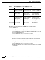
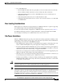
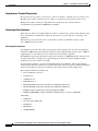
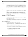
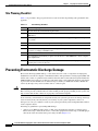
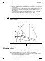
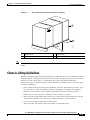
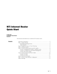
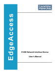
C H A P T E R
3
Preparing Your Site for Installation
Before you install the Cisco ASR1000 Series Aggregation Services Routers, consider:
•
The power and cabling requirements that must be in place at your installation site
•
The equipment required to install the router
•
The environmental conditions your installation site must meet to maintain normal operation
This chapter contains important safety information you should know before working with the Cisco
ASR 1000 Series Aggregation Services Routers and guides you through the process of preparing your
site for router installation.
Note
Do not unpack the system until you are ready to install it. Keep the chassis in the shipping container to
prevent accidental damage until you determined an installation site. Use the appropriate unpacking
documentation included with the system.
This chapter contains the following sections:
•
Safety Recommendations, page 3-2
•
Safety Warnings, page 3-2
•
Site Planning, page 3-6
•
Preventing Electrostatic Discharge Damage, page 3-16
•
Electrical Safety, page 3-17
•
Receiving a Cisco ASR 1000 Series Router, page 3-18
•
Chassis-Lifting Guidelines, page 3-19
•
Tools and Equipment, page 3-20
•
Checking the Shipping Container Contents, page 3-20
•
Cisco ASR 1000 Series Router Installation Checklist, page 3-22
Cisco ASR 1000 Series Aggregation Services Routers Hardware Installation and Initial Configuration Guide
OL-13208-01
3-1
Chapter 3
Preparing Your Site for Installation
Safety Recommendations
Safety Recommendations
The following guidelines will help to ensure your own safety and protect your Cisco equipment. This list
does not cover all potentially hazardous situations, so be alert.
•
Cisco safety policy is that all of its routers must conform to the requirements of IEC 60950, with
appropriate national deviations, as a minimum. In addition, Cisco routers must also meet the
requirements of any other normative documents (for example, standards, technical specifications,
laws or regulations).
•
Review the safety warnings listed in the Regulatory Compliance and Safety Information for the
Cisco ASR 1000 Series Aggregation Services Routers that accompanied your Cisco ASR 1000 Series
Router, before installing, configuring, or maintaining the router.
•
Never attempt to lift an object that might be too heavy for you to lift by yourself.
•
Always turn all power supplies off and unplug all power cables before opening the chassis.
•
Always unplug the power cable before installing or removing a chassis.
•
Keep the chassis area clear and dust free during and after installation.
•
Keep tools and chassis components away from walk areas.
•
Do not wear loose clothing, jewelry (including rings and chains), or other items that could get caught
in the chassis. Fasten your tie or scarf and sleeves.
•
The Cisco ASR 1000 Series Routers operate safely when it is used in accordance with its marked
electrical ratings and product usage instructions.
Safety Warnings
Read the installation instructions in this document before you connect the system to its power source.
Failure to read and follow these guidelines could lead to an unsuccessful installation and possibly
damage to the system and components.
You should observe the following safety guidelines when working with any equipment that connects to
electrical power or telephone wiring. These guidelines help you avoid injuring yourself or damaging the
devices.
Compliance Requirements
This section includes Safety Compliance and Network Equipment Building Systems (NEBS) standards.
The Cisco ASR1000 Series routers are in compliance with national and international standards as
described in Table 1.
Cisco ASR 1000 Series Aggregation Services Routers Hardware Installation and Initial Configuration Guide
3-2
OL-13208-01
Chapter 3
Preparing Your Site for Installation
Standard Warning Statements
Table 1
Compliance Requirements
Safety Compliance and NEBS Requirements
Specification
Description
Safety
To comply with the Telecom port Conducted emissions requirements of EN55022:1998 and
CISPR22:2003- shielded-twisted pair cables must be used with the 8-port channelized
T1/E1 SPA interface. EN55022: Revisions 73-8358-05 through 73-8358-08
NEBS
To comply with the Telcordia GR-1089 NEBS standard for electromagnetic compatibility
and safety, for Ethernet RJ-45 ports, use only shielded Ethernet cables that are grounded
on both ends. In a NEBS installation, all Ethernet ports are limited to intrabuilding wiring.
Note
The English warnings in this document are followed by a statement number. To see the translations of a
warning into other languages, look up its statement number in the Regulatory, Compliance, and Safety
Information for the Cisco Aggregation Services Router 1000 Series document.
Standard Warning Statements
This section describes the warning definition and then lists core safety warnings grouped by topic.
Warning
This warning symbol means danger. You are in a situation that could cause bodily injury. Before you
work on any equipment, be aware of the hazards involved with electrical circuitry and be familiar
with standard practices for preventing accidents. Use the statement number provided at the end of
each warning to locate its translation in the translated safety warnings that accompanied this device.
Note: SAVE THESE INSTRUCTIONS
Statement 1071
General Safety Warnings
Warning
Read the installation instructions before you connect the system to its power source. Statement 1004
Warning
Ultimate disposal of this product should be handled according to all national laws and regulations.
Statement 1040
Warning
No user-serviceable parts inside Do not open. Statement 1040
Warning
Installation of the equipment must comply with local and national electrical codes. Statement 1074
Cisco ASR 1000 Series Aggregation Services Routers Hardware Installation and Initial Configuration Guide
OL-13208-01
3-3
Chapter 3
Preparing Your Site for Installation
Standard Warning Statements
Warning
To comply with the Class A emissions requirements of EN55022 and CISPR22- shielded twisted pair
T1/E1 cables must be used for SPA-8-Port Channelized T1/E1 SPA (SPA-8XCHT1/E1). EN55022/CISPR22
Statement
Warning
To comply with the FCC Class A emissions requirements- shielded twisted pair T1/E1 cables must be
used with SPA-8-Port Channelized T1/E1 SPA (SPA-8XCHT1/E1). EN55022/CISPR22 Statement
Warning
Power cable and AC adapter - When installing the product, please use the provided or designated
connection cables/power cables/AC adaptors. Using any other cables or adapters could cause a
malfunction or a fire. Electrical Appliance and Material Safety Law prohibits the use of certified
cables (that have the ‘UL’ shown on the code) for any other electrical devices than products
designated by Cisco. The use of cables that are certified by Electrical Appliance and Material Safety
Law (that have ‘PSE’ shown on the code) is not limited to Cisco-designated products. Statement 371
Warning
Only trained and qualified personnel should be allowed to install or replace this equipment
Statement 1030
Warning
This product relies on the building’s installation for short-circuit (overcurrent) protection. Ensure that
the protective device is rated not greater than: AC power supplies for the Cisco ASR 1004 Router, Cisco
ASR 1006 Router, and Cisco ASR 1002 Router: 120 VAC, 20A U.S. maximum. DC power supplies for the
Cisco ASR 1004 Router: 40A U.S. maximum. DC power supplies for the Cisco ASR 1006 Router: 50A U.S.
maximum. DC power supplies for the ASR 1002 Router: 30A U.S. maximum.. Statement 1005
Warning
This product requires short-circuit (overcurrent) protection to be provided as part of the building
installation. Install only in accordance with national and local wiring regulations. Statement 1045
Warning
This unit may have more than one power supply connection. All connections must be removed to
de-energize the unit. Statement 1028
Warning
The plug-socket combination must be accessible at all times, because it serves as the main
disconnecting device. Statement 1019
Warning
Hazardous voltage or energy may be present on the DC power terminals. Always replace cover when
terminals are not in service. Be sure uninsulated conductors are not accessible when cover is in
place. Statement 1075
Warning
Use copper conductors only. Statement 1025
Cisco ASR 1000 Series Aggregation Services Routers Hardware Installation and Initial Configuration Guide
3-4
OL-13208-01
Chapter 3
Preparing Your Site for Installation
Standard Warning Statements
Warning
This equipment must be grounded. Never defeat the ground conductor or operate the equipment in the
absence of a suitably installed ground conductor. Contact the appropriate electrical inspection
authority or an electrician if you are uncertain that suitable grounding is available. Statement 1024
Warning
Hazardous voltage or energy is present on the backplane when the system is operating. Use caution
when servicing. Statement 1034
Warning
Class 1 laser product. Statement 1008
Warning
Class 1 LED product. Statement 1027
Warning
Laser radiation is present when the system is open. Statement 1009
Warning
Do not stare into the laser beam. Statement 1010
Warning
Class I(CDRH) and Class 1M (IEC) laser products. Statement 1055
Warning
Invisible laser radiation may be emitted from the end of the unterminated fiber cable or connector. Do
not view directly with optical instruments. Viewing the laser output with certain optical instruments
(for example, eye loupes, magnifiers, and microscopes) within a distance of 100 mm may pose an eye
hazard. Statement 1056
Warning
There is the danger of explosion if the battery is replaced incorrectly. Replace the battery only with
the same or equivalent type recommended by the manufacturer. Dispose of used batteries according
to the manufacturer’s instructions. Statement 1015
Warning
Do not touch or bridge the metal contacts on the battery. Unintentional discharge of the batteries can
cause serious burns. Statement 341
Warning
To prevent personal injury or damage to the chassis, never attempt to lift or tilt the chassis using the
handles on modules (such as power supplies, fans, or cards); these types of handles are not designed
to support the weight of the unit. Statement 1032
Warning
To prevent the system from overheating, do not operate it in an area that exceeds the maximum
recommended ambient temperature of: 40 degrees C. Statement 1047
Cisco ASR 1000 Series Aggregation Services Routers Hardware Installation and Initial Configuration Guide
OL-13208-01
3-5
Chapter 3
Preparing Your Site for Installation
Site Planning
Warning
This equipment must be externally grounded using a customer-supplied ground wire before power is
applied. Contact the appropriate electrical inspection authority or an electrician if you are uncertain
that suitable grounding is available. Statement 366
Warning
Blank faceplates and cover panels serve three important functions: they prevent exposure to
hazardous voltages and currents inside the chassis; they contain electromagnetic interference (EMI)
that might disrupt other equipment; and they direct the flow of cooling air through the chassis. Do not
operate the system unless all cards, faceplates, front covers, and rear covers are in place.
Site Planning
This section contains site planning information, and will help you plan for the installation of the
Cisco ASR 1000 Series routers. It contains the following sections:
•
General Precautions, page 3-6
•
Site Selection Guidelines, page 3-7
•
Floor Loading Considerations, page 3-9
•
Site Power Guidelines, page 3-9
•
Site Cabling Guidelines, page 3-11
•
Rack-Mounting and Location Guidelines, page 3-13
•
Site Planning Checklist, page 3-16
General Precautions
Observe the following general precautions when using and working with your Cisco ASR1000 Series
system.
•
Keep your system components away from radiators and heat sources and do not block cooling vents.
•
Do not spill food or liquids on your system components and never operate the product in a wet
environment.
•
Do not push any objects into the openings of your system components. Doing so can cause fire or
electric shock by shorting out interior components.
•
Position system cables and power supply cables carefully. Route system cables and the power supply
cable and plug so that they cannot be stepped on or tripped over. Be sure that nothing else rests on
your system components’ cables or power cable.
•
Do not modify power cables or plugs. Consult a licensed electrician or your power company for site
modifications. Always follow your local and national wiring rules.
•
If you turn off your system, wait at least 30 seconds before turning it on again to avoid system
component damage.
Cisco ASR 1000 Series Aggregation Services Routers Hardware Installation and Initial Configuration Guide
3-6
OL-13208-01
Chapter 3
Preparing Your Site for Installation
Site Planning
Site Selection Guidelines
The Cisco ASR 1000 Series Routers require specific environmental operating conditions. Temperature,
humidity, altitude, and vibration can affect the performance and reliability of the router. The following
sections provide specific information to help you plan for the proper operating environment.
The Cisco ASR1000 Series Routers are designed to meet the industry EMC, safety, and environmental
standards described in the Regulatory, Safety, and Compliance Information for Cisco ASR 1000 Series
Aggregation Services Routers document.
Site Environmental Requirements
Environmental monitoring in the Cisco ASR1000 Series router protects the system and components from
damage caused by excessive voltage and temperature conditions. To ensure normal operation and avoid
unnecessary maintenance, plan and prepare your site configuration before installation. After installation,
make sure the site maintains the environmental characteristics as shown in Table 3-2.
Table 3-2
Cisco ASR 1000 Series Router Environmental Tolerances
Environmental Characteristic
Minimum
Maximum
Steady State Operating
0 degree C
50 degree C
(50 degrees C at 10,000
feet)
Storage
–20 degrees C
+70 degrees C
Humidity operating (noncondensing)
10%
90%
Humidity nonoperating (noncondensing)
5%
95%
Altitude operating: over allowable temperature
range (0 to 50 degrees C)
–500 feet
10,000 feet
Altitude, nonoperating: over allowable temperature
range
–1000 feet
50,000 feet
Thermal shock non-operating with change over time –25 degrees C
of 3 minute
+70 degrees C
Thermal Shock - Operating at 2.5 degree C per
minute
+50 degrees C
0 degrees C
Physical Characteristics
Be familiar with the physical characteristics of the Cisco ASR 1000 Series Router to assist you in placing
the system in the proper location.
Table 3-3 shows the weight and dimensions of the Cisco ASR 1000 Series Routers.
Cisco ASR 1000 Series Aggregation Services Routers Hardware Installation and Initial Configuration Guide
OL-13208-01
3-7
Chapter 3
Preparing Your Site for Installation
Site Planning
Table 3-3
Physical Characteristics of Cisco ASR 1000 Series Router
Characteristic
Cisco ASR 1006 Router
Cisco ASR 1004 Router
Cisco ASR 1002 Router
Height
10.47 in. (26.543 cm) 6RU rack-mount per EIA
RS-310 standard
6.95 in. (17.653 cm) 4RU rack-mount per EIA
RS-310 standard
3.47 in. (8.813 cm) - 2RU
rack-mount per EIA RS-310
Width
17.25 in. (43.815 cm) - 19 17.25 (43.815 cm) - 19
inch rack-mount
inch rack- mount or
optional 23 Telco rack
mount
Depth
22.50 in. (57.15 cm)
(including card handles,
cable-management
brackets, power supply
handles).
Weight of fully 75 lbs (34.019 kg)
configured
chassis
17.25 in. (43.815 cm) 19-inch rack-mount or
optional 23 Telco rack
mount
22.50 in.(57.15 cm)
(including card handles,
cable-management
brackets, and power
supply handles)
22.50 in. (57.15 cm)
(including card handles,
cable-management brackets,
and power supply handles)
for mounting in a
600mm-enclosed cabinet
50 lbs (22.679 kg)
40 lbs (18.143 kg)
The following list describes additional Cisco ASR 1000 Series chassis characteristics:
•
Cisco ASR 1006 Router:
– Chassis height meets EIA-310 rack spacing 6RU (10.47/266mm), universal rack mount
– Chassis width meets EIA-310 19inch (17.25/438.15mm) wide with rack brackets
– Cable-management brackets at each Cisco ASR 1000 Series SPA Interface (SIP) locations can
hold 16 ports of STP/UTP RJ 45 cables
– Cable-management brackets allow for 1.5 inch bend radii for cables
– Adjustable rack mount brackets allow for a front to rear rail variance distance of 15.50/394mm
to 19.00/482.6mm
•
Cisco ASR 1004 Router:
– Chassis height meets EIA-310 rack spacing 4RU (6.95 in/176.53mm), universal rack mount
– Chassis width meets EIA-310 19inch (17.25/438.15mm) wide with rack brackets
– Cable-management brackets at each Cisco ASR 1000 Series SPA Interface (SIP) locations can
hold 16 ports of STP/UTP RJ 45 cables
– Cable-management brackets allow for 1.5 inch bend radii for cables
– Adjustable rack mount brackets allow for a front to rear rail variance distance of 15.50/394mm
to 19.00/482.6mm
Cisco ASR 1000 Series Aggregation Services Routers Hardware Installation and Initial Configuration Guide
3-8
OL-13208-01
Chapter 3
Preparing Your Site for Installation
Site Planning
•
Cisco ASR 1002 Router:
– Chassis height meets EIA-310 rack spacing 2RU (3.47 in/ 88.138mm), universal rack mount
– Chassis width meets EIA-310 19inch (17.25/438.15mm) wide with rack brackets
– Cable-management brackets at the Cisco ASR 1002 Router location can hold 16 ports of
STP/UTP RJ 45 cables
– Cable-management brackets allow for 1.5 inch bend radii for cables
– Adjustable rack mount brackets allow for a front to rear rail variance distance of 15.50/394mm
to 19.00/482.6mm
Floor Loading Considerations
Ensure that the floor under the rack supporting the Cisco 1000 Series Routers is capable of supporting
the combined weight of the rack and all other installed equipment.
To assess the weight of the fully configured Cisco 1000 Series Router respectively, refer to Table 3-3.
For additional information about floor loading requirements, consult the document GR-63-CORE,
Network Equipment Building System (NEBS) Requirements: Physical Protection.
Site Power Guidelines
The Cisco 1000 Series Router has specific power and electrical wiring requirements. Adhering to these
requirements ensures reliable operation of the system. Follow these precautions and recommendations
when planning your site the Cisco ASR 1000 Series Router:
Caution
Note
•
The redundant power option provides a second, identical power supply to ensure that power to the
chassis continues uninterrupted if one power supply fails or input power on one line fails.
•
In systems configured with the redundant power option, connect each of the two power supplies to
a separate input power source. If you fail to do this, your system might be susceptible to total power
failure due to a fault in the external wiring or a tripped circuit breaker.
•
To prevent a loss of input power, be sure the total maximum load on each circuit supplying the power
supplies is within the current ratings of the wiring and breakers.
•
Check the power at your site before installation and periodically after installation to ensure that you
are receiving clean power. Install a power conditioner if necessary.
•
Provide proper grounding to avoid personal injury and damage to the equipment due to lightning
striking power lines or due to power surges. The chassis ground must be attached to a central office
or other interior ground system.
This product requires short-circuit (overcurrent) protection, to be provided as part of the building
installation. Install only in accordance with national and local wiring regulations.
The Cisco 1000 Series Router installation must comply with all applicable codes and is approved for use
with copper conductors only. The ground bond fastening hardware should be of compatible material and
preclude loosening, deterioration, and electrochemical corrosion of hardware and joined material.
Attachment of the chassis ground to a central office or other interior ground system must be made with
an AWG #6 gauge wire, copper ground conductor at a minimum.
Cisco ASR 1000 Series Aggregation Services Routers Hardware Installation and Initial Configuration Guide
OL-13208-01
3-9
Chapter 3
Preparing Your Site for Installation
Site Planning
Electrical Circuit Requirements
Each Cisco 1000 Series Router requires a dedicated electrical circuit. If you equip it with dual power
feeds, provide a separate circuit for each power supply to avoid compromising the power redundancy
feature.
The Cisco ASR 1000 Series Routers can be powered by a DC or AC source. Ensure that the equipment
grounding is present and observe power strip ratings. Make sure that the total ampere rating of all
products plugged into the power strip does not exceed 80% of the rating.
Table 3-4 contains specifications for DC powered systems for all Cisco ASR 1000 Series Routers.
Table 3-4
Cisco ASR 1000
Series Router DC
Power Supply
Cisco ASR 1000 Series Router DC Power Supply System Input Requirements
System Input Rating (Amps)
Circuit Breaker Amps
Minimum
Maximum
AWG # Wire
Minimum
Maximum
Cisco ASR 1006
40
Always 50
Always AWG #6 wire
Cisco ASR 1004
24
30
40
10
8
Cisco ASR 1002
16
20
30
12
10
For example, the Cisco ASR 1002 Router DC power supply, with 16 Amp input rating must use an AWG #12 gauge wire for a 20Amp circuit breaker and
an AWG #10 gauge wire for a 30Amp circuit breaker.
Note
All Cisco ASR 1000 Series Router AC power supplies require a 20 AMP circuit breaker.
The AC and DC power supplies for the Cisco ASR 1000 Series Routers support different types of power
supply switches. Table 3-5 defines which power supplies the Cisco ASR 1000 Series routers support (a
Standby or an On/Off switch).
Table 3-5
Cisco ASR 1000 Series Routers AC and DC Power Supply Switches
Switch Type
Supported
On/Off circuit
Symbol
Cisco ASR 1000 Series Router Power Supply
I/O
ASR 1006 DC
ASR 1004 DC
ASR 1002 AC
ASR 1006 AC
Standby Switch A broken
circle with ASR 1004 AC
a vertical
ASR 1002 DC
line
through the
top of it
Cisco ASR 1000 Series Aggregation Services Routers Hardware Installation and Initial Configuration Guide
3-10
OL-13208-01
Chapter 3
Preparing Your Site for Installation
Site Planning
Table 3-6 lists AC and DC power supply system rating requirements for all Cisco ASR 1000 Series
Routers.
Table 3-6
AC and DC Power Supply System Rating Specifications for the Cisco ASR 1000 Series Routers
Description
Specification
Power supply declared ratings
AC = 100-240 VAC
DC = –48/ –60 VDC
Line frequency rating
50/60 Hz
Site Cabling Guidelines
This section contains guidelines for wiring and cabling at your site. When preparing your site for
network connections to the Cisco 1000 Series Router, consider the type of cable required for each
component, and the cable’s limitations. Consider the distance limitations for signaling, EMI, and
connector compatibility. Possible cable types are fiber, thick or thin coaxial, foil twisted-pair, or
unshielded twisted-pair cabling.
Also consider any additional interface equipment you need, such as transceivers, hubs, switches,
modems, channel service units (CSUs), or data service units (DSUs).
Note
Warning
The E1 interface on the Cisco 8-Port Channelized T1/E1 SPA interface uses RJ-48c receptacles for E1
(120-Ohm) cables with RJ-45 connectors. You can use all ports simultaneously. Each E1 connection
supports interfaces that meet the G.703 standards. The RJ-45 connection does not require an external
transceiver. The E1 ports are E1 interfaces that use 120-ohm shielded twisted-pair (STP) cables.
Shielded T1/E1 cables must be used to comply with FCC/EN55022/CISPR22 Class A emissions
requirements on the 8-port channelized T1/E1 SPA interface.
Before you install the Cisco 1000 Series Router, have all additional external equipment and cables on
hand. For ordering information, contact a customer service representative.
The extent of your network and the distances between network interface connections depend in part on
the following factors:
•
Signal type
•
Signal speed
•
Transmission medium
The distance and rate limits referenced in the following sections are the IEEE-recommended maximum
speeds and distances for signaling purposes. Use this information as a guideline in planning your
network connections prior to installing the Cisco 1000 Series Router.
If wires exceed recommended distances, or if wires pass between buildings, give special consideration
to the effect of a lightning strike in your vicinity. The electromagnetic pulse caused by lightning or other
high-energy phenomena can easily couple enough energy into unshielded conductors to destroy
electronic devices. If you have had problems of this sort in the past, you may want to consult experts in
electrical surge suppression and shielding.
Cisco ASR 1000 Series Aggregation Services Routers Hardware Installation and Initial Configuration Guide
OL-13208-01
3-11
Chapter 3
Preparing Your Site for Installation
Site Planning
Asynchronous Terminal Connections
The route processor provides a console port to connect a terminal or computer for local console access.
The RP1 also provides an auxiliary port to connect to a modem for remote dial-in console access.
Both ports have RJ-45 connectors, support RS-232 asynchronous data, and have distance
recommendations specified in the IEEE RS-232 standard.
Interference Considerations
When wires are run for any significant distance, there is a risk that stray signals will be induced on the
wires as interference. If interference signals are strong, they can cause data errors or damage to the
equipment.
The following sections describe sources of interference and how to minimize its effects on the
Cisco 1000 Series Router system.
Electromagnetic Interference
All equipment powered by AC current can propagate electrical energy that can cause electromagnetic
interference (EMI) and possibly affect the operation of other equipment. The typical sources of EMI are
equipment power cords and power service cables from electric utility companies.
Strong EMI can destroy the signal drivers and receivers in the Cisco 1000 Series Router and even create
an electrical hazard by causing power surges through power lines into installed equipment. These
problems are rare, but could be catastrophic.
To resolve these problems, you need specialized knowledge and equipment, which could consume
substantial time and money. However, you should ensure that you have a properly grounded and shielded
electrical environment, paying special attention to the need for electrical surge suppression.
Electromagnetic Emissions Certification:
•
FCC 47 CFR Part 15 Class A
•
VCCI Class A
•
AS/NSZ Class A
•
ICES-003 Class A
•
EN55022/CISPR 22 Information Technology Equipment (Emissions)
•
EN55024/CISPR 24 Information Technology Equipment (Immunity)
•
EN300 386 Telecommunications Network Equipment (EMC)
•
EN50082-1/EN61000-6-1 Generic Immunity Standard Same as for Cisco ASR 1002
CE marking:
•
UL60950-1
•
CSA C22.2 No. 60950-1-03
•
EN 60950-1
•
IEC 60950-1
•
AS/NZS 60950.1
Cisco ASR 1000 Series Aggregation Services Routers Hardware Installation and Initial Configuration Guide
3-12
OL-13208-01
Chapter 3
Preparing Your Site for Installation
Site Planning
Radio Frequency Interference
When electromagnetic fields act over a long distance, radio frequency interference (RFI) can be
propagated. Building wiring can often act as an antenna, receiving the RFI signals and creating more
EMI on the wiring.
If you use twisted-pair cable in your plant wiring with a good distribution of grounding conductors, the
plant wiring is unlikely to emit radio interference. If you exceed the recommended distances, use a
high-quality twisted-pair cable with one ground conductor for each data signal.
Lightning and AC Power Fault Interference
If signal wires exceed recommended cabling distances, or if signal wires pass between buildings, you
should consider the effect that a lightning strike in your vicinity might have on the Cisco 1000 Series
Router.
The electromagnetic pulse (EMP) generated by lightning or other high-energy phenomena can couple
enough energy into unshielded conductors to damage or destroy electronic equipment. If you have
previously experienced such problems, you should consult with RFI/EMI experts to ensure that you have
adequate electrical surge suppression and shielding of signal cables in your Cisco 1000 Series Router
operating environment.
Rack-Mounting and Location Guidelines
The Cisco 1000 Series Router is designed for standalone, two-post 19 inch rack-mount, four-post 19 inch
rack-mount and closed cabinet systems with front and rear doors. You can mount the Cisco 1000 Series
Router on an equipment shelf or tabletop.
The sections that follow describe criteria for selecting a rack to mount the Cisco 1000 Series Router,
guidelines for placing the rack for reliable operation, and safety precautions to take to prevent bodily
injury when mounting a Cisco ASR1000 Series system in a rack.
Precautions for Rack-Mounting
The following rack-mount guidelines are provided to ensure your safety:
•
Do not move large racks by yourself. Due to the height and weight of a rack, a minimum of two
people are required to accomplish this task.
•
Ensure that the rack is level and stable before extending a component from the rack.
•
Ensure that proper airflow is provided to components in the rack.
•
Do not step or stand on any component or system when servicing other systems or components in a
rack.
•
When mounting the Cisco 1000 Series Router in a partially filled rack, load the rack from the bottom
to the top with the heaviest component at the bottom of the rack.
•
If the rack is provided with stabilizing devices, then install the stabilizers before mounting or
servicing the unit in the rack.
Cisco ASR 1000 Series Aggregation Services Routers Hardware Installation and Initial Configuration Guide
OL-13208-01
3-13
Chapter 3
Preparing Your Site for Installation
Site Planning
Rack Selection Guidelines
The Cisco 1000 Series Router can be mounted in most two-post or four-post, 19-inch equipment racks
that comply with the Electronics Industries Association (EIA) standard for equipment racks (EIA-310-D
19-inch). The rack must have at least two posts with mounting flanges to mount the chassis.
Caution
When mounting a chassis in any type of rack equipment, make certain the inlet air to the chassis does
not exceed 55C.
The distance between the center lines of the mounting holes on the two mounting posts must be 18.31
inches ± 0.06 inch (46.50 cm ± 0.15 cm). The rack-mounting hardware included with the chassis is
suitable for most 19-inch equipment racks.
We recommend that you mount the Cisco 1000 Series Router in an equipment rack which includes the
necessary rack-mounting hardware which is suitable for most 19-inch equipment racks.
Consider installing the Cisco 1000 Series Router in a rack with the following features:
Note
•
NEBS compliant, 19-inch (48.3 cm) wide rack.
•
EIA or ETSI hole patterns in the mounting rails. Required mounting hardware is shipped with the
Cisco 1000 Series Router. If the rack that you plan to install the system in has metric-threaded rails,
you must provide your own metric mounting hardware.
•
Perforated top and open bottom for ventilation to prevent overheating.
•
Leveling feet for stability.
The Cisco 1000 Series Router should not be installed in an enclosed rack because the chassis requires
an unobstructed flow of cooling air to maintain acceptable operating temperatures for its internal
components. Installing the router in any type of enclosed rack—even with the front and back doors
removed—could disrupt the air flow, trap heat next to the chassis, and cause an overtemperature
condition inside the router. If you use an enclosed rack, make certain that there are air vents on all sides
of the rack and there is proper ventilation.
Equipment Rack Guidelines
The placement of the rack can affect personnel safety, system maintenance, and the system ability to
operate within the environmental characteristics described in Table 3-2 on page 3-7. Choose a proper
location for the Cisco 1000 Series Router by following the guidelines below.
Locating for Safety
If the Cisco 1000 Series Router is the heaviest or the only piece of equipment in the rack, consider
installing it at or near the bottom to ensure that the rack’s center of gravity is as low as possible.
For additional information about the proper placement of electronic equipment, consult the document
GR-63-CORE, Network Equipment Building System (NEBS) Requirements: Physical Protection.
Locating for Easy Maintenance
Keep at least 3 feet of clear space in front and behind the rack. This space ensures that you can remove
the Cisco 1000 Series Router components and perform routine maintenance and upgrades easily.
Cisco ASR 1000 Series Aggregation Services Routers Hardware Installation and Initial Configuration Guide
3-14
OL-13208-01
Chapter 3
Preparing Your Site for Installation
Site Planning
Avoid installing the Cisco 1000 Series Router in a congested rack and consider how the routing of cables
from other pieces of equipment in the same rack could affect access to the routers cards.
The front and top of the chassis must remain unobstructed to ensure adequate airflow and prevent
overheating inside the chassis.
Allow the following clearances for normal system maintenance:
•
At the top of the chassis—At least 3 inches (7.6 cm)
•
In the front of the chassis—3 to 4 ft (91.44 cm to 121.92 cm)
To avoid problems during installation and ongoing operation, follow these general precautions when you
plan the equipment locations and connections:
•
Use the show environment all command regularly to check the internal system status. The
environmental monitor continually checks the interior chassis environment; it provides warnings for
high temperature and creates reports on any occurrences. If warning messages are displayed, take
immediate action to identify the cause and correct the problem.
•
Keep the Cisco 1000 Series Router off of the floor and out of areas that collect dust.
•
Follow ESD prevention procedures to avoid damage to equipment. Damage from static discharge
can cause immediate or intermittent equipment failure.
Locating for Proper Airflow
Ensure the location of the Cisco 1000 Series Router has enough airflow to keep the system operating
within the environmental characteristics and the air temperature is sufficient to compensate for the heat
dissipated by the system.
Avoid locating the Cisco 1000 Series Router in a location in which the chassis air intake vents could
draw in the exhaust air from adjacent equipment. Consider how the air flows through the Cisco 1000
Series Router. The Cisco 1000 Series Router airflow direction is front to back with ambient air drawn in
from the venting located on the chassis front sides.
Cisco ASR 1000 Series Aggregation Services Routers Hardware Installation and Initial Configuration Guide
OL-13208-01
3-15
Chapter 3
Preparing Your Site for Installation
Preventing Electrostatic Discharge Damage
Site Planning Checklist
Table 3-7 is provided to help you perform and account for all the site planning tasks presented in this
appendix.
Table 3-7
Site Planning Checklist
Site Planning Requirements
The site meets the environmental requirements.
The site’s air conditioning system can compensate for the heat dissipation of the Cisco ASR
1000 Series.
The floor space that the Cisco ASR 1000 Series Routers occupy can support the weight of
the system).
Electrical service to the site complies with the requirements.
The electrical circuit servicing the Cisco ASR 1000 Series complies with the requirements).
Consideration has been given to the console port wiring, and limitations of the cabling
involved, according to TIA/EIA-232F.
The Cisco 1000 Series Router Ethernet cabling distances are within limitations.
The equipment rack in which you plan to install the Cisco ASR 1000 Series chassis complies
with requirements.
Careful consideration has be given to safety, ease of maintenance, and proper airflow in
selecting the location of the rack.
Preventing Electrostatic Discharge Damage
Electrostatic discharge (ESD) damage, occurs when electronic cards or components are improperly
handled and can result in complete or intermittent failures. The performance routing engine (PRE), and
all line cards consist of a printed circuit card that is fixed in a metal carrier. Electromagnetic interference
(EMI) shielding and connectors are integral components of the carrier. Although the metal carrier helps
to protect the cards from ESD, use an antistatic strap each time you handle the modules. Handle the
carriers by the edges only; never touch the cards or connector pins.
Caution
Always tighten the captive installation screws on all system components when you are installing them.
These screws prevent accidental removal of the module, provide proper grounding for the system, and
help to ensure that the bus connectors are properly seated in the backplane.
Static electricity can harm delicate components inside your system. To prevent static damage, discharge
static electricity from your body before you touch any of your system components, such as an
microprocessor. As you continue to work on your system, periodically touch an unpainted metal surface
on the computer chassis.
Following are guidelines for preventing ESD damage:
•
Always use an ESD-preventive wrist or ankle strap and ensure that it makes good skin contact.
Before removing a card from the chassis, connect the equipment end of the strap to the ESD plug at
the bottom of the chassis below the power entry modules (Figure 3-1).
Cisco ASR 1000 Series Aggregation Services Routers Hardware Installation and Initial Configuration Guide
3-16
OL-13208-01
Chapter 3
Preparing Your Site for Installation
Electrical Safety
Caution
•
Handle line cards by the faceplates and carrier edges only; avoid touching the card components or
any connector pins.
•
When removing a card, place the removed module component-side-up on an antistatic surface or in
a static-shielding bag. If the module will be returned to the factory, immediately place it in a
static-shielding bag.
•
Avoid contact between the modules and clothing. The wrist strap protects the card from ESD
voltages on the body only; ESD voltages on clothing can still cause damage.
•
When transporting a sensitive component, first place it an antistatic container or packaging.
•
Handle all sensitive components in a static-safe area. If possible, use antistatic floor pads and
workbench pads.
For safety, periodically check the resistance value of the antistatic strap. The measurement should be
between 1 and 10 ohms.
Figure 3-1
ESD Chassis Grounding Stud
4
2
280034
3
1
1
Chassis earth ground studs and lead wire
3
Earth ground connector on the chassis
2
Grounding screws
4
Earth ground symbol
Electrical Safety
All system components are hot-swappable. They are designed to be removed and replaced while the
system is operating without presenting an electrical hazard or damage to the system.
Follow these basic guidelines when you are working with any electrical equipment:
•
Before beginning any procedures requiring access to the chassis interior, locate the emergency
power-off switch for the room in which you are working.
Cisco ASR 1000 Series Aggregation Services Routers Hardware Installation and Initial Configuration Guide
OL-13208-01
3-17
Chapter 3
Preparing Your Site for Installation
Receiving a Cisco ASR 1000 Series Router
•
Disconnect all power and external cables before installing or removing a chassis.
•
Do not work alone when potentially hazardous conditions exist.
•
Never assume that power has been disconnected from a circuit; always check.
•
Do not perform any action that creates a potential hazard to people or makes the equipment unsafe.
Never install equipment that appears damaged.
•
Carefully examine your work area for possible hazards such as moist floors, ungrounded power
extension cables, and missing safety grounds.
In addition, use the guidelines that follow when working with any equipment that is disconnected from
a power source but is still connected to telephone wiring or other network cabling.
Warning
•
Never install telephone wiring during a lightning storm.
•
Never install telephone jacks in wet locations unless the jack is specifically designed for wet
locations.
•
Never touch uninsulated telephone wires or terminals unless the telephone line has been
disconnected at the network interface.
•
Use caution when installing or modifying telephone lines.
Do not work on the system or connect or disconnect cables during periods of lightning activity.
Statement 1001
Receiving a Cisco ASR 1000 Series Router
Each Cisco ASR1000 Series chassis is shipped in a container that is strapped to a pallet as illustrated in
Figure 3-2.
Cisco ASR 1000 Series Aggregation Services Routers Hardware Installation and Initial Configuration Guide
3-18
OL-13208-01
Chapter 3
Preparing Your Site for Installation
Chassis-Lifting Guidelines
Figure 3-2
Cisco ASR 1000 Series Router Packaged for Shipping
1
132823
2
3
Note
1
Outside carton
2
Pallet
3
Packing straps
We recommend that you have at least two people available to help with the installation and ensure safe
lifting.
Chassis-Lifting Guidelines
The fully configured system weighs approximately 75 pounds. The chassis is not intended to be moved
frequently. Before you install the system, ensure that your site is properly prepared so you can avoid
having to move the chassis later to accommodate power sources and network connections.
Two or more people are required to lift the chassis. Each time you lift the chassis or any heavy object,
follow these guidelines:
•
Never attempt to lift the chassis by yourself. Because of the size and weight of the chassis, use at
least two people to safely lift and move it without causing injury or damaging the equipment.
•
Ensure that your footing is solid, and balance the weight of the chassis between your feet.
•
Lift the chassis slowly; never move suddenly or twist your body as you lift.
•
Keep your back straight and lift with your legs, not your back. If you must bend down to lift the
chassis, bend at the knees, not at the waist, to reduce the strain on your back muscles.
•
Do not remove installed components from the chassis.
•
Always disconnect all external cables before lifting or moving the chassis.
Cisco ASR 1000 Series Aggregation Services Routers Hardware Installation and Initial Configuration Guide
OL-13208-01
3-19
Chapter 3
Preparing Your Site for Installation
Tools and Equipment
Step 1
Each person should stand on either side of the chassis and place one hand under the air intake at the
bottom front of the chassis.
Step 2
With the other hand, grasp the top rear of the chassis under the air exhaust and carefully lift the chassis.
Tools and Equipment
The tools and equipment listed below are recommended as the minimum necessary to install the
Cisco ASR 1000 Series Router. You may need additional tools and equipment to install associated
equipment and cables. You may also require test equipment to check electronic and optical signal levels,
power levels, and communications links.
•
Phillips hand screwdriver
•
A 3.5mm flat-blade screwdriver
•
Tape measure (optional)
•
Level (optional)
•
Power drill
Unpacking and Verifying Shipping Contents
When you receive your chassis, perform the following steps and use the shipping contents checklist from
the next section:
Step 1
Inspect the box for any shipping damage. (if there is damage contact your service representative).
Step 2
Unpack the Cisco ASR 1000 Series Router.
Step 3
Perform a visual inspection of the chassis.
Step 4
After you have unpacked the system verify that you have received all of the required components. Using
the packing list as a guide, take the following steps to check the contents of the Cisco ASR 1000 Series
Router shipping container:
Step 5
Check the contents of the boxes containing accessory items. Verify that you have received all equipment
listed in your order.
Step 6
Check that all Cisco ASR 1000 Series RP1s, Cisco ASR1000-ESP10s, Cisco ASR1000-ESP5, Cisco
ASR 1000 Series SPA Interface (SIPs), and power supplies you ordered are installed in the chassis.
Ensure that the configuration matches the packing list.
Checking the Shipping Container Contents
Use the components list to check the contents of the Cisco ASR 1000 Series Router shipping container.
Do not discard the shipping container. You need the container if you move or ship the Cisco ASR 1000
Series Router in the future.
Cisco ASR 1000 Series Aggregation Services Routers Hardware Installation and Initial Configuration Guide
3-20
OL-13208-01
Chapter 3
Preparing Your Site for Installation
Checking the Shipping Container Contents
Table 3-8
Cisco ASR 1000 Series Router Shipping Container Contents List
Component
Description
Chassis
Cisco ASR 1000 Series Router configured with dual AC or dual DC
power supplies and a shared port adapter blank panel if a shared port
adapter has not been ordered.
Accessories Kit
Front and rear chassis rack-mount brackets that you will attach to the
chassis with the respective screws
Received
Three sets of screws, one set for:
•
Front rack-mount brackets (use the black screws)
•
Rear rack-mount brackets (use the package with the 5 screws)
•
Cable-management brackets (use the 4 screw package)
Two cable-management brackets with ‘U’ feature design devices
attached; a different size for each chassis.
ESD, Wrist Strap (disposable)
1 disposable wrist strap
Documentation
Regulatory Compliance and Safety Information for Cisco Aggregation
Services 1000 Series Chassis document
Optional Equipment
Power cord if an AC power supply was shipped. There are none for the
DC power supply units.
Note
Most Cisco documentation is online or on the Cisco Documentation DVD. Documentation that ships
with your Cisco ASR1000 Series router includes the Regulatory Compliance and Safety Information for
the Cisco Aggregation Services Router 1000 Series document, and the Cisco Aggregation Services
Router 1000 Series Documentation Roadmap that contains documentation titles and the URLs to them
online. See also the “Related Documentation” section on page xviii.
Cisco ASR 1000 Series Aggregation Services Routers Hardware Installation and Initial Configuration Guide
OL-13208-01
3-21
Chapter 3
Preparing Your Site for Installation
Cisco ASR 1000 Series Router Installation Checklist
Cisco ASR 1000 Series Router Installation Checklist
To assist you with your installation and to provide a historical record of what was done by whom,
photocopy the Cisco ASR 1000 Series Router Installation Checklist. Use this to indicate when each
procedure or verification is completed. When the checklist is completed, place it in your site log along
with the other records for your new router.
Table 3-9
Cisco ASR 1000 Series Router Installation Checklist
Verified
By
Task
Date
Date chassis received
Chassis and all accessories unpacked
Types and numbers of interfaces verified
Safety recommendations and guidelines reviewed
Installation Checklist copied
Site log established and background information entered
Site power voltages verified
Site environmental specifications verified
Required passwords, IP addresses, device names, and so on, available
Required tools available
Network connection equipment available
Cable-management bracket installed (optional but recommended)
AC power cable(s) connected to AC source(s) and router
DC power cable(s) connected to DC source(s) and router
Network interface cables and devices connected
System power turned on
System boot complete (STATUS LED is on)
Shared port adapters are operational
Correct hardware configuration displayed after system banner appears
Cisco ASR 1000 Series Aggregation Services Routers Hardware Installation and Initial Configuration Guide
3-22
OL-13208-01