1
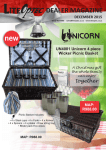
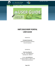
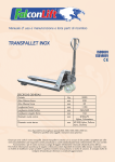
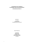
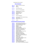
2 HP PRESSURE WASHER
1300 PSI
Model 92146
ASSEMBLY AND OPERATING INSTRUCTIONS
®
3491 Mission Oaks Blvd., Camarillo, CA 93011
Visit our Web site at: http://www.harborfreight.com
TO PREVENT SERIOUS INJURY,
READ AND UNDERSTAND ALL WARNINGS
AND INSTRUCTIONS BEFORE USE.
Copyright© 2004 by Harbor Freight Tools®. All rights reserved. No portion of this
manual or any artwork contained herein may be reproduced in any shape or form
without the express written consent of Harbor Freight Tools.
For technical questions or replacement parts, please call 1-800-444-3353.
PRODUCT SPECIFICATIONS
Item
Description
Electrical Requirements
120V / 60 Hz / 13 Amps / 3400 RPM
3-Prong GFCI Power Plug
35 Ft. Long Power Cord (16 AWG x 3C)
Automatic Star t and Stop
Water Pressure
1300 PSI
Flow Rate
1.7 Gallons Per Minute
Hose Length
16 Ft.
Lance Total Length
33-1/4"
Accessories
Detergent Bottle
Garden Hose Adapter
Weight
27.5 Pounds
Recommended Water Supply
3.4 GPM (3 GPM Minimum)
Minimum Water Intake Hose I.D.
0'-50' = 5/8"
50'-100' = 3/4"
E193752
SAVE THIS MANUAL
You will need this manual for the safety warnings and precautions, assembly, operating,
inspection, maintenance and cleaning procedures, parts list and assembly diagram.
Keep your invoice with this manual. Write the invoice number on the inside of the front
cover. Keep this manual and invoice in a safe and dry place for future reference.
UNPACKING
When unpacking, check to make sure all the parts shown on the Parts Lists on pages 17
and 19 are included. If any parts are missing or broken, please call Harbor Freight Tools
at the number shown on the cover of this manual as soon as possible.
GENERAL SAFETY RULES
IMPORTANT SAFETY INSTRUCTIONS
WARNING!
READ AND UNDERSTAND ALL INSTRUCTIONS
Failure to follow all instructions listed in the following
pages may result in electric shock, fire, and/or serious injury.
SAVE THESE INSTRUCTIONS
SKU 92146
For technical questions, please call 1-800-444-3353.
PAGE 2
WORK AREA
1.
Keep your work area clean and well lit. Cluttered benches and dark areas
invite accidents.
2.
Do not operate power tools in explosive atmospheres, such as in the
presence of flammable liquids, gases, or dust. Power tools create sparks
which may ignite flammables.
3.
Keep bystanders, children, and visitors away while operating a power tool.
Distractions can cause you to lose control. Protect others in the work area from
debris such as chips and sparks. Provide barriers or shields as needed.
ELECTRICAL SAFETY
1.
Grounded tools must be plugged into an outlet properly installed and
grounded in accordance with all codes and ordinances. Never remove the
grounding prong or modify the plug in any way. Do not use any adapter
plugs. Check with a qualified electrician if you are in doubt as to whether
the outlet is properly grounded. If the tools should electrically malfunction or
break down, grounding provides a low resistance path to carry electricity away
from the user.
2.
Avoid body contact with grounded surfaces such as pipes, radiators,
ranges, and refrigerators. There is an increased risk of electric shock if your
body is grounded.
3.
Do not expose power tools to rain or wet conditions. Water entering a power
tool will increase the risk of electric shock.
4.
Do not abuse the Power Cord. Never use the Power Cord to carry the tools
or pull the Plug from an outlet. Keep the Power Cord away from heat, oil,
sharp edges, or moving parts. Replace damaged Power Cords immediately. Damaged Power Cords increase the risk of electric shock.
5.
When operating a power tool outside, use an outdoor extension cord
marked “W-A” or “W”. These extension cords are rated for outdoor use, and
reduce the risk of electric shock.
SKU 92146
For technical questions, please call 1-800-444-3353.
PAGE 3
PERSONAL SAFETY
1.
Stay alert. Watch what you are doing, and use common sense when operating a power tool. Do not use a power tool while tired or under the influence of drugs, alcohol, or medication. A moment of inattention while operating power tools may result in serious personal injury.
2.
Dress properly. Do not wear loose clothing or jewelry. Contain long hair.
Keep your hair, clothing, and gloves away from moving parts. Loose
clothes, jewelry, or long hair can be caught in moving parts.
3.
Avoid accidental starting. Be sure the Power Switch is off before plugging
in. Carrying power tools with your finger on the Power Switch/Trigger, or plugging
in power tools with the Power Switch on, invites accidents.
4.
Remove adjusting keys or wrenches before turning the power tool on. A
wrench or a key that is left attached to a rotating part of the power tool may result
in personal injury.
5.
Do not overreach. Keep proper footing and balance at all times. Proper
footing and balance enables better control of the power tool in unexpected
situations.
6.
Use safety equipment. Always wear eye protection. Non-skid safety shoes,
hard hat, or hearing protection must be used for appropriate conditions. Always
wear ANSI approved safety impact goggles and thick rubber boots during use
and maintenance.
TOOL USE AND CARE
1.
Use clamps or other practical ways to secure and support the workpiece to
a stable platform. Holding the work by hand is unstable and may lead to loss of
control. Only work on a workpiece that is properly secured. Holding any object
while it is pressure washed can cause serious personal injury by the high pressure stream.
2.
Do not force the tool. Use the correct tool for your application. The correct
tool will do the job better and safer at the rate for which it is designed. Do not use
small equipment, tools, or attachments to do the work of larger industrial equipment, tools, or attachments. Do not use this product for a purpose for which it was
not intended.
3.
Do not use the power tool if the Power Switch does not turn it on or off. Any
tool that cannot be controlled with the Power Switch is dangerous and must be
replaced.
SKU 92146
For technical questions, please call 1-800-444-3353.
PAGE 4
4.
Disconnect the Power Cord Plug from the power source before making any
adjustments, changing accessories, or storing the tool. Such preventive
safety measures reduce the risk of starting the tool accidentally.
5.
Store idle tools out of reach of children and other untrained persons. Tools
are dangerous in the hands of untrained users.
6.
Maintain tools with care. Maintain tools with care. Keep tools clean. Properly
maintained tools are easier to control. Do not use a damaged tool. Tag damaged
tools “Do not use” until repaired.
7.
Check for misalignment or binding of moving parts, breakage of parts, and
any other condition that may affect the tool’s operation. If damaged, have
the tool serviced before using. Many accidents are caused by poorly maintained tools.
8.
Use only accessories that are recommended by the manufacturer for your
model. Accessories that may be suitable for one tool may become hazardous
when used on another tool.
SERVICE
1.
Tool service must be performed only by qualified repair personnel. Service
or maintenance performed by unqualified personnel could result in a risk of injury.
2.
When servicing a tool, use only identical replacement parts. Follow
instructions in the “Inspection, Maintenance, And Cleaning” section of this
manual. Use of unauthorized parts or failure to follow maintenance instructions
may create a risk of electric shock or injury.
SPECIFIC SAFETY RULES
1.
Maintain a safe working environment. Keep the work area well lit. Make sure
there is adequate surrounding workspace. Always keep the work area free of
obstructions, grease, oil, trash, and other debris. Do not use the Pressure Washer
in areas near flammable chemicals, dusts, and vapors.
2.
Maintain labels and nameplates on the Pressure Washer. These carry important information. If unreadable or missing, contact Harbor Freight Tools for a
replacement.
3.
WARNING! RISK OF INJECTION OR SEVERE INJURY!
Keep clear of Nozzle. Do not direct discharge stream at people or animals.
Keep the work area clear of all people and animals.
SKU 92146
For technical questions, please call 1-800-444-3353.
PAGE 5
4.
Use the right product for the right job. There are certain applications for which
this product was designed. Do not use small equipment, tools, or attachments to
do the work of larger industrial equipment, tools, or attachments. Do not use this
product for a purpose for which it was not intended.
5.
This product must continuously run with cold water only. Never use hot
water. Dry running will cause serious damage to the seals. Make sure the
water supply used for the Pressure Washer is not dirty, sandy, and does not contain any corrosive chemical products.
6.
To avoid electrical shock, never start or run the Pressure Washer in the rain.
Never allow water to leak inside the Body of the Pressure Washer. Do not direct
discharge stream at the Pressure Washer itself, its Cord or Plug, or at other live
electrical equipment.
7.
Do not allow the Ground Fault Circuit Interrupter to become wet. Always
place the GFCI in a dry location and as far away as possible from the object
being sprayed. Keep all electrical connections dry and off the ground.
8.
When using the Pressure Washer, always maintain a firm grip on the Wash
Gun with both hands. Squeezing the Trigger of the Wash Gun causes a kickback force.
9.
Do not pull or carry the Power Washer by its Power Cord, or pull the Cord
around sharp corners or edges. Do not unplug the Power Washer by pulling on
the Cord. Keep the Cord away from heated surfaces.
10.
Do not handle the Ground Fault Circuit Interrupter with wet hands.
11.
Avoid unintentional starting. Make sure you are prepared to begin work before
turning on the Pressure Washer.
12.
The work area should have adequate drainage to reduce the possibility of a
fall due to slippery surfaces.
13.
This product is intended for outdoor residential use only.
14.
Some chemicals or detergents may be harmful if inhaled or ingested. Use
an ANSI approved respirator or mask whenever there is a chance that vapors
may be inhaled.
15.
Keep the High Pressure Hose connected to the Pressure Washer and Spray
Gun while the system is pressurized. Disconnecting the Pressure Hose while
the unit is pressurized is dangerous, and may cause injury.
16.
Prior to starting the Pressure Washer in cold weather, check all of the parts
of the unit to make sure ice has not formed. Do not store the unit where the
temperature will fall below 32° F (0° C). (See “Inspection, Maintenance, and
Cleaning” section.)
SKU 92146
For technical questions, please call 1-800-444-3353.
PAGE 6
17.
This Pressure Washer requires a minimum water input flow of 3 gallons per
minute.
18.
When dispensing detergent, apply the detergent to the cleaning area at low
pressure only. Then, spray the detergent off the cleaning area by using the
adjustable Nozzle.
19.
CAUTION: The high pressure water flow can damage the work surface if
not used properly. Always test the spray in an open area first.
20.
Never move the Pressure Washer by pulling on the High Pressure Hose.
Use the Handle provided on the top of the unit.
21.
NEVER leave the Pressure Washer unattended when it is plugged into an
electrical outlet. It is hazardous to leave this unit unattended, especially
with an inadequate water supply. Turn off the Pressure Washer and unplug it
from its electrical outlet before leaving.
22.
If water is leaking out of the Pressure Washer, immediately shut off the unit.
Unplug the Pressure Washer, and discharge all pressure before tightening
fittings or having repair work done by a qualified technician.
23.
WARNING! People with pacemakers should consult their physician(s) before
using this product. Operation of electrical equipment in close proximity to a
heart pacemaker could cause interference to, or failure of the pacemaker.
24.
WARNING! The warnings and precautions discussed in this manual cannot
cover all possible conditions and situations that may occur. It must be under
stood by the operator that common sense and caution are factors which cannot
be built into this product, but must be supplied by the operator.
SAVE THESE INSTRUCTIONS
GROUNDING
WARNING!
Improperly connecting the grounding wire can result in the risk of electric
shock. Check with a qualified electrician if you are in doubt as to whether the
outlet is properly grounded. Do not modify the power cord plug provided with
the tool. Never remove the grounding prong from the plug. Do not use the
tool if the power cord or plug is damaged. If damaged, have it repaired by
a service facility before use. If the plug will not fit the outlet, have a proper
outlet installed by a qualified electrician.
SKU 92146
For technical questions, please call 1-800-444-3353.
PAGE 7
GROUNDED TOOLS: TOOLS WITH THREE PRONG PLUGS
1.
Tools marked with “Grounding Required” have a three wire cord and three prong
grounding plug. The plug must be connected to a properly grounded outlet. If
the tool should electrically malfunction or break down, grounding provides a low
resistance path to carry electricity away from the user, reducing the risk of
electric shock. (See Figure A.)
2.
The grounding prong in the plug is connected through the green wire inside the
cord to the grounding system in the tool. The green wire in the cord must be the
only wire connected to the tool’s grounding system and must never be attached
to an electrically “live” terminal. (See Figure A.)
3.
Your tool must be plugged into an appropriate outlet, properly installed and
grounded in accordance with all codes and ordinances. The plug and outlet
should look like that in the following illustration. (See Figure A.)
3-PRONG PLUG
ELECTRICAL OUTLET
FIGURE A
EXTENSION CORDS
1.
Grounded tools require a three wire extension cord.
2.
As the distance from the supply outlet increases, you must use a heavier gauge
extension cord. Using extension cords with inadequately sized wire causes a
serious drop in voltage, resulting in loss of power and possible tool damage.
(See Figure B, next page.)
3.
The smaller the gauge number of the wire, the greater the capacity of the cord.
For example, a 14 gauge cord can carry a higher current than a 16 gauge cord.
(See Figure B.)
4.
When using more than one extension cord to make up the total length, make sure
each cord contains at least the minimum wire size required. (See Figure B.)
5.
If you are using one extension cord for more than one tool, add the nameplate
amperes and use the sum to determine the required minimum cord size.
(See Figure B.)
SKU 92146
For technical questions, please call 1-800-444-3353.
PAGE 8
6.
If you are using an extension cord outdoors, make sure it is marked with the suffix
“W-A” (“W” in Canada) to indicate it is acceptable for outdoor use.
7.
Make sure your extension cord is properly wired and in good electrical condition.
Always replace a damaged extension cord or have it repaired by a qualified
electrician before using it.
8.
Protect your extension cords from sharp objects, excessive heat, and damp or wet
areas.
9.
If an extension cord is needed, only use a cord with the proper gauge wire.
(See Figure B.)
RECOMMENDED MINIMUM WIRE GAUGE FOR EXTENSION CORDS*
(120 VOLT)
NAMEPLATE
AMPERES
(At Full Load)
0-2.0
2.1-3.4
3.5-5.0
5.1-7.0
7.1-12.0
12.1-16.0
16.1-20.0
FIGURE B
EXTENSION CORD LENGTH
25
FEET
18
50
FEET
18
75
FEET
18
100
FEET
18
150
FEET
16
18
18
18
18
18
16
16
14
14
12
18
16
14
12
12
16
14
12
10
-
14
12
10
-
-
-
-
12
10
*Based on limiting the line voltage drop
to five volts at 150% of the rated amperes.
WARNING: NEVER use 16 or 18 gauge extension cords
of any length on this Pressure Washer.
SYMBOLOGY
Double Insulated
Canadian Standards
Association
Underwriters
Laboratories, Inc.
V~
A
no
xxxx/min.
Volts Alternating
Current
Amperes
No Load Revolutions
Per Minute (RPM)
FIGURE C
SKU 92146
For technical questions, please call 1-800-444-3353.
PAGE 9
PRODUCT FEATURES AND PRECAUTIONS
NOTICE: Prior to using the pressure washer for the first time, it is IMPORTANT
that it has been determined that there is an adequate water supply.
The Pressure Washer needs TWICE the volume of the stated water
output (1.7 GPM). This Pressure Washer will need 3.4 GPM to operate correctly and efficiently. If the water is supplied by a well, make
certain that the well produces enough water to keep up with the Pressure Washer’s water demand.
FLOW RATE OF THE
WATER SUPPLY MUST NEVER FALL BELOW 3 GPM. Flow rate
can be determined by running the water at full pressure (valve completely open) for one minute into an empty 5 gallon container, then
measuring the amount of water in the container.
CAUTION!
If the pump is run without an adequate water supply, the Pressure Washer will cavitate. Cavitation causes the pump to vibrate
and operate loudly, and will damage the pump.
1.
IMPORTANT! Prior to turning on the Pressure Washer connect the unit to the
water supply. Turn on the water and squeeze the Trigger (23A) until water flows
out of the Wash Gun. This removes air from the system and allows the unit to
properly perform. Failure to follow this Step will damage the Pump.
2.
The Pressure Washer features an automatic ON/OFF Micro Switch (27). The
Motor (33) of the Pressure Washer does not run continuously, but only when the
Trigger (23A) is squeezed. When spraying water through the unit stops, the Motor
will automatically shut off.
3.
The Pressure Washer features a 3-Prong,
Ground Fault Circuit Interrupter (GFCI)
Power Plug (59). The GFCI Power Plug provides additional protection from the risk of
electrical shock. Make sure the Trigger (23A) is
released before plugging in. Plug the GFCI
Power Plug into a grounded, 120 volt, electrical outlet. Press the TEST button and then the
RESET button. The indicator on the Power Plug
should appear red. If the indicator is not red
after several tries, have both the Power Plug
and receptacle inspected by a qualified electrician. Should replacement of the GFCI Power
Plug become necessary, only a qualified technician should perform the service. Never
attempt to alter or disable the GFCI Power Plug.
(See Figure D.)
SKU 92146
RESET
RED LIGHT
TEST
FIGURE D
For technical questions, please call 1-800-444-3353.
PAGE 10
4.
NOTE: The Pressure Washer will not pressurize if the Nozzle is not completely
assembled. It will not work properly with only part of the Wand installed.
5.
The Pressure Washer is equipped with a Trigger Safety Lock (25A). When the
Pressure Washer is not in use, use the Safety Lock to avoid accidentally engaging
the high pressure spray. To engage the Safety Lock, lower the Lever and snap it into
the Trigger (23A). (See Figure E.)
TRIGGER SAFETY
LOCK
(25A)
TRIGGER
(23A)
FIGURE E
Pre-Operation Tips:
1.
The optimum angle for spraying water against a surface is 45 degrees. A 90
degree angle or direct impact of the water onto the surface can cause dirt particles to become imbedded in the cleaning surface and debris and high speed
water to reflect back at the operator.
2.
The distance between the Nozzle and the cleaning surface directly affects the
impact force of the water. The closer the Nozzle is to the surface, the stronger the
impact.
3.
The use of detergents can dramatically reduce cleaning time and assist in the
removal of stains. Detergents work best when applied at low pressure. Only use
non-corrosive detergents specifically designed for pressure washer use.
4.
The cleaning power of detergents comes from applying them to a surface and
giving the chemicals time to breakdown the dirt and grime.
SKU 92146
For technical questions, please call 1-800-444-3353.
PAGE 11
ASSEMBLY AND OPERATING INSTRUCTIONS
NOTE: For additional references to the parts listed in the following pages, refer to the
Assembly Diagrams on pages 18 and 19.
To Set Up The Pressure Washer:
1.
Attach the Spray Wand Extension (11A) to the Gun by inserting the tip of the
Wand into the Gun Collar. Then push in firmly and rotate to secure the Wand to
the Gun. (See Figure F.)
2.
The Spray Wand (13A) and Detergent Bottle (34A) can be attached to the Spray
Wand Extension (11A) in the same manner, by pushing in the accessory and
rotating to secure the accessory to the Spray Wand Extension. (See Figure F.)
SPRAY WAND EXTENSION SPRAY WAND
(11A)
(13A)
GUN
GUN COLLAR
DETERGENT BOTTLE
(34A)
FIGURE F
3.
Remove the protective plastic caps from the unit’s water Inlet Port (17) and water
Outlet Port (1). (See Figure G.)
4.
Firmly attach the Garden Hose Adapter (58) to the water Inlet Port (17).
(See Figure G.)
5.
Firmly attach the High Pressure Hose (55) to the water Outlet Port (1).
(See Figure G.)
OUTLET PORT (1)
HIGH PRESSURE HOSE (55)
INLET PORT (17)
GARDEN HOSE ADAPTER (58)
FIGURE G
SKU 92146
For technical questions, please call 1-800-444-3353.
PAGE 12
6.
Attach a garden hose (not included) of the appropriate size (5/8 - 3/4” ID) to the
Garden Hose Adapter (58). Then attach the other end of the garden hose to a
cold water faucet, and fully turn on the water supply. CAUTION! Use only cold
water in this Pressure Washer. (See Figure G.)
7.
Plug the Power Cord Plug into a 120 volt, grounded, electrical outlet. Then,
squeeze the Trigger (23A) and allow water to flow through the Wand.
(See Figure H.)
8.
Press the Power Switch (52) to the ON position (or “O” symbol) located at the rear
of the unit. Raise the Safety Lock (25A) to actuate the use of the Trigger (23A).
NOTE: The Pressure Washer will not operate until the Trigger is squeezed. The
Motor of the Pressure Washer will not run continuously. The Motor only runs while
the Trigger is being squeezed. (See Figure H.)
SAFETY LOCK
(25A)
TRIGGER
(23A)
FIGURE H
9.
When finished spraying, release the Trigger (23A). To disable the Trigger, lower
the Safety Lock (25A) and snap it into the Trigger. CAUTION! Always lock the
Trigger before making any spray pattern adjustments. (See Figure H.)
10.
When the work is complete, press the Power Switch (52) to the OFF position (or “I”
symbol).
11.
Make sure to shut off the water supply and discharge any water pressure from the
Pressure Washer in a safe direction by squeezing the Trigger (23A). (See Fig. H.)
Warning: Be certain to unplug the power plug with dry hands when done. If the
switch is left on the motor will run with no water, potentially causing damage
to the electrical circuit and causing the unit to burn up, voiding the warranty.
To Adjust The Spray Pattern:
1.
The angle of the spray coming out of the Spray Wand (13A) may be adjusted by
rotating the Knob (16A). This will vary the spray pattern from approximately a 0
degree narrow, high impact stream, to a 60 degree wide fan spray.
(See Figure J, next page.)
2.
The narrow stream works well to deep clean a concentrated area. This setting
has a very high impact, providing maximum cleaning power, but can possibly
damage surfaces. Use caution, as a concentrated pattern can cause damage to
the surface being pressure washed. (See Figure J.)
3.
A wide fan pattern distributes the impact of the water over a larger area. This
pattern allows large areas to be cleaned more quickly. (See Figure J.)
SKU 92146
For technical questions, please call 1-800-444-3353.
PAGE 13
WARNING:
NEVER adjust the knob
while the trigger is not
locked in the off position.
SPRAY WAND (13A)
KNOB (16A)
HIGH IMPACT STREAM
WIDE FAN SPRAY
FIGURE J
To Apply A Detergent:
1.
Make sure the Pressure Washer is turned off and unplugged from its electrical outlet.
2.
Unscrew and remove the top of the Detergent Bottle (34A) and fill it with a mild
detergent speciffically designed for pressure washing use (not included). Never
use caustic or abrasive detergents. Then, replace the top of the Detergent Bottle.
(See Figure F, page 12.)
3.
Remove the Spray Wand (13A), and replace it with the Detergent Bottle (34A).
(See Figure F.)
4.
Plug the Power Cord Plug into an electrical outlet, turn on the water flow, and squeeze
the Trigger (23A) and allow water to flow through the Wand. Then, turn on the Pressure Washer.
5.
Apply the detergent so that it thoroughly covers the cleaning surface. NOTE: Detergents work best when applied at low pressure. Apply from bottom to top of the
object being cleaned to prevent the detergent from sliding down and streaking.
6.
Allow the detergent to remain on the surface for several minutes. Lightly scrub
heavily soiled areas with a soft brush or cloth. Do not allow the detergent to dry on
the surface to be cleaned.
7.
Turn off the Pressure Washer, and unplug its Power Cord Plug from the electrical
outlet. Turn off the water supply, and discharge any remaining pressure safely.
8.
Remove the Detergent Bottle (34A) from the Spray Wand Extension (11A), and replace it with the Spray Wand (13A). (See Figure F.)
9.
Plug the Power Cord Plug into an electrical outlet, turn on the water flow, and squeeze
the Trigger (23A) and allow water to flow through the Wand. Then, turn on the Pressure Washer.
10.
Thoroughly rinse the detergent from the cleaning surface.
11.
When finished, turn off the Pressure Washer, and unplug its Power Cord Plug from
the electrical outlet.
SKU 92146
For technical questions, please call 1-800-444-3353.
PAGE 14
Shutdown Precautions:
1.
Make sure to rinse out the Detergent Bottle (34A).
2.
When the work is complete, press the Power Switch (52) to the OFF position (or “I”
symbol) to turn off the Motor.
3.
Turn off the water supply and disconnect the power plug from the outlet.
4.
Squeeze the Trigger (23A) of the Gun to depressurize the system.
5.
Wipe all surfaces of the Pressure Washer with a damp, clean cloth.
6.
CAUTION! Always turn off the Pressure Washer’s Motor before turning off
the unit’s water supply. Serious damage may occur to the Pump and/or the Motor
if the unit is run without water.
7.
WARNING! Never disconnect the High Pressure Hose (55) from the machine
while the system is still pressurized. To depressurize the unit, turn off the Motor.
Turn off the water supply, and squeeze the Trigger (23A) several times.
How To Avoid Damaging Surfaces:
1.
Adjust the Knob (16A) to a wide fan pattern before plugging in or switching on the
gun. (See Figure J.)
2.
Place the Nozzle at a 45 degree angle to the cleaning surface.
3.
Keep the stream moving throughout the cleaning process.
4.
This Pressure Washer can, at different distances, remove dirt from painted
surfaces, remove paint, or even chip concrete. Always use the proper distance for the surface and application. Harbor Freight Tools cannot be held
responsible for any damage caused by misuse of the high pressure stream.
INSPECTION, MAINTENANCE, AND CLEANING
1.
WARNING! Make sure the Power Switch of the Pressure Washer is in its
“OFF” position and that the unit is unplugged from its electrical outlet, and all
pressure is released, before performing any inspection, maintenance, or cleaning
procedures. Point the Wash Gun in a safe direction and discharge all remaining
pressure. Then, disconnect the garden hose from the unit.
2.
Before each use, inspect the general condition of the Pressure Washer. Check
for loose screws, misalignment or binding of moving parts, damaged electrical
wiring, damaged High Pressure Hose, damaged accessories, plugged water
SKU 92146
For technical questions, please call 1-800-444-3353.
PAGE 15
inlet/ Filter (18), and any other condition that may affect its safe operation. If
abnormal noise or vibration occurs, have the problem corrected before further
use.
Do not use damaged equipment.
3.
To clean, remove excess water from the Pump by tipping the unit on both sides to
drain any remaining water from the inlet and outlet fittings. Drain the Detergent
Dispenser and flush with running water. Use only a clean cloth and mild detergent to clean the body of the Pressure Washer. Do not use solvents. Do not immerse any part of the tool in liquid. Dry off any remaining water on all parts and
fittings. Then engage the Trigger Safety Lock.
4.
When storing, always completely empty the Pressure Washer of water. Frost will
damage the Pressure Washer if the unit contains water. Store the Pressure
Washer indoors in a dry, frost-free room. Minerals in the water can harden inside
the workings. Flush the unit with automotive antifreeze prior to long-term storage.
5.
To Clean The Nozzle:
A clog in the Nozzle (19A) can significantly reduce the amount of water that
comes out of the Pressure Washer. A clog can also cause the unit to pulsate
while in use. To clean out the Nozzle:
A.
Turn off the Pressure Washer, and unplug the unit from its electrical outlet.
B.
Turn off the cold water supply.
C.
Release any remaining water pressure in the Pressure Washer by squeezing the Trigger (23A) in a safe direction. (See Figure H, page 13.)
D.
Remove the Spray Wand Extension (11A) from the Gun. (See Figure F.)
E.
Rotate the Knob (16A) to the High Impact Stream setting. (See Figure J.)
F.
Insert the tip of a Tip Cleaner (not included) or thin (about 1/32” dia.), rigid,
wire into the end of the Nozzle hole and rotate the Tip Cleaner back and
forth until the debris is dislodged. Then, remove the Tip Cleaner or wire.
(See Figure K.)
SPRAY WAND EXTENSION (11A)
FIGURE K
SKU 92146
KNOB (16A)
TIP CLEANER
(NOT INCLUDED)
For technical questions, please call 1-800-444-3353.
PAGE 16
PARTS LIST
Part #
1
2
3
4
5
6
7
8
9
10
11
12
13
14
15
16
17
18
19
20
21
22
23
24
25
26
27
28
29
30
Description
Outlet Port
O-Ring (22 x 2.4mm)
Core Valve Cap
Ball
Spring (0.8 x 4.8 x 6.5 x 10)
Copper Valve Core
Plastic Valve Base
O-Ring (16 x 2.4mm)
Copper Piston
Spring (2 x 14.5 x 5 x 26)
Copper Load Release Valve Base
O-Ring (15 x 2.4mm)
Load Release Valve Core (3CR13)
Alloy Pump Head
Hex Screw (M6 x 15mm)
O-Ring (18 x 2.4mm)
Inlet Port
Filter
Switch Top Lance
Spring Base
Pressure Switch Lower Cover
O-Ring (10 x 1.9mm)
O-Ring (22 x 2.4mm)
Copper Screw Connector
Hand Spike
Spring (1 x 7.8 x 9 x 19)
Micro Switch
Alloy Pump Body
Hex Screw (M8 x 20mm)
Bearing (8107)
Qty.
1
1
1
1
1
1
1
1
1
1
1
1
1
1
4
1
1
1
1
1
1
1
1
1
1
1
1
1
1
1
Part #
31
32
33
34
35
36
37
38
39
40
41
42
43
44
45
46
47
48
49
50
51
52
53
54
55
56
57
58
59
Description
Alloy Bearing Housing
O-Ring (88 x 2.4mm)
Motor
O-Ring (14 x 1.9mm)
Inlet/Outlet Valve
O-Ring (16 x 1.9mm)
Copper In/Out Valve Cap Washer
Rubber Canvassed U-Ring
O-Ring (24 x 1.9mm)
Middle Ringer
O-Ring (16 x 1.9mm)
Frame Oil Seal (22 x 12 x 5mm)
Plunger Spring
Plunger (3CR13)
Plunger Follower
Rubber Ring
Connection Box Spring
Screw
Capacitor
Connection Box
Power Cord Clamp
Power Switch
Rubber Cover Ring
Shell
High Pressure Hose
Handle
Wheel
Garden Hose Adapter
Ground Fault Circuit Interrupter
Qty.
1
1
1
6
6
6
6
3
3
3
3
3
3
3
3
1
1
5
1
1
1
1
1
1
1
1
2
1
1
60
Cord
1
PLEASE READ THE FOLLOWING CAREFULLY
THE MANUFACTURER AND/OR DISTRIBUTOR HAS PROVIDED THE PARTS LIST AND ASSEMBLY
DIAGRAM IN THIS MANUAL AS A REFERENCE TOOL ONLY. NEITHER THE MANUFACTURER OR
DISTRIBUTOR MAKES ANY REPRESENTATION OR WARRANTY OF ANY KIND TO THE BUYER THAT HE
OR SHE IS QUALIFIED TO MAKE ANY REPAIRS TO THE PRODUCT, OR THAT HE OR SHE IS QUALIFIED
TO REPLACE ANY PARTS OF THE PRODUCT. IN FACT, THE MANUFACTURER AND/OR DISTRIBUTOR
EXPRESSLY STATES THAT ALL REPAIRS AND PARTS REPLACEMENTS SHOULD BE UNDERTAKEN BY
CERTIFIED AND LICENSED TECHNICIANS, AND NOT BY THE BUYER. THE BUYER ASSUMES ALL
RISK AND LIABILITY ARISING OUT OF HIS OR HER REPAIRS TO THE ORIGINAL PRODUCT OR
REPLACEMENT PARTS THERETO, OR ARISING OUT OF HIS OR HER INSTALLATION OF REPLACEMENT
PARTS THERETO.
SKU 92146
For technical questions, please call 1-800-444-3353.
PAGE 17
59
58
60: CORD NOT SHOWN.
ASSEMBLY DIAGRAM
o
o
o
NOTE:
Some parts are listed and shown for illustration purposes only, and are not
available individually as replacement parts.
SKU 92146
For technical questions, please call 1-800-444-3353.
PAGE 18
PARTS LIST - CONTINUED
Part #
1A
2A
3A
4A
5A
6A
7A
8A
9A
10A
11A
12A
13A
14A
15A
16A
17A
Description
Casing (Right)
Casing (Left)
Spring
O-Ring
Back Up Ring
Piston Valve
O-Ring
Spring
O-Ring
Valve Body
Spray Wand Extension
Turnbuckle
Spray Wand
Blade Compressor
O-Ring
Knob
O-Ring
Qty.
1
1
1
2
2
1
1
2
2
1
1
1
1
1
1
1
1
Part #
18A
19A
20A
21A
22A
23A
24A
25A
26A
27A
28A
29A
30A
31A
32A
33A
Description
O-Ring
Nozzle
Lamella
Pin
U-Pin
Trigger
Self Tapping Screw
Safety Lock
High Pressure Hose
Jacket
Jacket
Connector
Nut
Coupling
O-Ring
Coupling
Qty.
1
1
1
1
1
1
6
1
1
1
1
2
1
1
1
1
34A
Detergent Bottle
1
ASSEMBLY DIAGRAM - CONTINUED
16A
15A
18A
17A
13A
14A
9A
1A
8A
11A
21A
9A 8A
25A
10A
20A
4A
19A
5A
22A
4A
3A
7A
26A
6A
23A
28A
31A
12A
32A
33A
29A
30A
27A
34A
24A
2A
NOTE:
Some parts are listed and shown for illustration purposes only, and are not
available individually as replacement parts.
SKU 92146
For technical questions, please call 1-800-444-3353.
PAGE 19