1
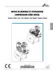
EARTH AUGER
9 HP ROBIN® ENGINE
Model 94143
Set up And Operating Instructions
Caution
Your warranty is voided if:
1. You do not put hydraulic oil in the Auger’s oil assembly prior to its first use.
Before each use, check the oil level. Never run the Auger with low or no hydraulic oil.
Running the Auger with low or no hydraulic oil will permanently damage the unit.
2. You do not put engine oil in the Engine’s crankcase prior to its first use.
Before each use, check the oil level. Never run the Engine with low or no engine oil.
Running the Engine with low or no oil will permanently damage the unit.
Diagrams within this manual may not be drawn proportionally.
Due to continuing improvements, actual product may differ slightly from the product described herein.
Distributed exclusively by Harbor Freight Tools®.
3491 Mission Oaks Blvd., Camarillo, CA 93011
Visit our website at: http://www.harborfreight.com
Read this material before using this product.
Failure to do so can result in serious injury.
Save this manual.
Copyright© 2006 by Harbor Freight Tools®. All rights reserved. No portion of this
manual or any artwork contained herein may be reproduced in any shape or form
without the express written consent of Harbor Freight Tools.
For technical questions or replacement parts, please call 1-800-444-3353.
Manual Revised 07k
SPECIFICATIONS
Digging Capacity
Hydraulic Pump Type
Auger Drive
Auger Bit Size
Controls
Tires
Maximum Speed
Hydraulic Oil Capacity
Recommended Hydraulic Oil
Hitch Type
Engine Type
8” Diameter x 36” Deep
Single Stage
2,000 PSI / 110 RPM / 3,800 in-lb Torque with Safety Relief Valve
8” Diameter x 36” Long with Safety Shear Pin (Included)
Forward and Reverse Operation / Rubber Grip Handles
Easy Access Kill Switch On Handle
Quantity: 2
Size: 4.8/4.00-8
Air Pressure: 60 PSI
Load Range: B
Maximum Load: 590 lb. Each
25 MPH
4 Gallons
10 Weight
2” Ball Hitch with Safety Chain
9 HP Robin® / Unleaded Gasoline Powered / Pull Start
Automatic Low Oil Shut Down
SAVE THIS MANUAL
You will need this manual for the safety warnings and precautions, assembly,
operating, inspection, maintenance and cleaning procedures, parts list and assembly
diagram. Keep your invoice with this manual. Write the invoice number on the inside
of the front cover. Keep this manual and invoice in a safe and dry place for future reference.
GENERAL SAFETY RULES AND PRECAUTIONS
WARNING! Read all instructions
Failure to follow all instructions listed below may result in fire, and/or
serious injury.
SAVE THESE INSTRUCTIONS
WORK AREA
1.
Keep your work area clean and well lit. Cluttered benches and dark areas
invite accidents.
Do not operate power tools in explosive atmospheres, such as in
the presence of flammable liquids, gases, or dust. Power tools
create sparks which may ignite the dust or fumes.
2.
3.
Keep bystanders away while operating a power tool. Distractions can cause
you to lose control. Protect others in the work area from debris such as chips
and sparks. Provide barriers or shields as needed.
REV 09b
SKU 94143
For technical questions, please call 1-800-444-3353
PAGE 2
PERSONAL SAFETY
1.
Stay alert. Watch what you are doing, and use common sense when operating a power tool. Do not use a power tool while tired or under the influence of drugs, alcohol, or medication. A moment of inattention while operating
power tools may result in serious personal injury.
2.
Dress properly. Do not wear loose clothing or jewelry. Contain long
hair. Keep your hair, clothing, and gloves away from moving parts. Loose
clothes, jewelry, or long hair can be caught in moving parts.
3.
Avoid accidental starting. Be sure the Gasoline Engine’s Power Switch is
in its “OFF” position before moving the Auger and before performing any
service, maintenance, or cleaning procedures on the unit.
4.
Remove adjusting keys or wrenches before turning the Auger on. A wrench
or a key that is left attached to a rotating part of the machine may result in personal injury.
5.
Do not overreach. Keep proper footing and balance at all times. Proper
footing and balance enables better control of the power tool in unexpected situations.
6.
Use safety equipment. Always wear eye protection. Always wear
ANSI-approved safety impact goggles when using this product. ANSIapproved hearing protection, helmet, and steel toed shoes must also be
used.
TOOL USE AND CARE
1.
Do not force the tool. Use the correct tool for your application. The correct
tool will do the job better and safer at the rate for which it is designed.
2.
Do not use the Auger if the Gasoline Engine’s Power Switch does not turn it
on or off. Any tool that cannot be controlled with its power switch is dangerous
and must be replaced.
3.
Store idle tools out of reach of children and other untrained persons. Tools
are dangerous in the hands of untrained users.
4.
Maintain tools with care. Properly maintained tools with a sharp cutting edge
are less likely to bind and are easier to control. Do not use a damaged tool. Tag
damaged tools “Do not use” until repaired.
5.
Check for misalignment or binding of moving parts, breakage of parts, and
any other condition that may affect the tool’s operation. If damaged, have
the tool serviced before using. Many accidents are caused by poorly maintained tools.
SKU 94143
For technical questions, please call 1-800-444-3353
PAGE 3
6.
Use only accessories that are recommended by the manufacturer for your
model. Accessories that may be suitable for one tool may become hazardous
when used on another tool.
SERVICE
1.
Tool service must be performed only by qualified repair personnel. Service
or maintenance performed by unqualified personnel could result in a risk of injury.
2.
When servicing a tool, use only identical replacement parts. Follow instructions in the “Inspection, Maintenance, And Cleaning” section of this
manual. Use of unauthorized parts or failure to follow maintenance instructions
may create a risk of electric shock or injury.
SPECIFIC SAFETY RULES AND PRECAUTIONS
Caution
Your warranty is voided if:
a. You do not put hydraulic oil in the Auger’s oil assembly prior to its first use.
Before each use, check the oil level. Never run the Auger with low or no hydraulic oil.
Running the Auger with low or no hydraulic oil will permanently damage the
unit.
b. You do not put engine oil in the Engine’s crankcase prior to its first use.
Before each use, check the oil level. Never run the Engine with low or no
engine oil.
Running the Engine with low or no oil will permanently damage the unit.
1.
Maintain labels and nameplates on the Auger. These carry important information. If unreadable or missing, contact Harbor Freight Tools for a replacement.
2.
DANGER! Avoid buried cables and pipes. The Auger will cut through
buried electrical cable and gas pipes, resulting in serious injury or death. Always
contact your local utilities companies before drilling.
3.
DANGER! Tip-over and crush hazard. This machine can roll away, tip over,
and crush you. Do not drill on inclines steeper than 15 degrees. The Auger is
extremely difficult to control on steep inclines.
4.
DANGER! This Auger is designed for outdoor use only. Do not operate the Auger in a closed area or in a poorly ventilated area. When running, the
Engine (15) of this Auger produces carbon monoxide, a colorless, odorless, toxic
fume that, when inhaled, can cause serious personal injury or death. Whenever
possible, use a carbon monoxide detector (not included) to detect excessive carbon monoxide fumes in the work area and in the surrounding area.
SKU 94143
For technical questions, please call 1-800-444-3353
PAGE 4
5.
DANGER! Debris entanglement. The rotating Bit (65) can get tangled in
debris left on the ground, and can result in personal injury and damage to the
machine. Before digging, make sure the area is clear of debris that can wind
around the Auger during operation.
6.
DANGER! Rotating Auger hazard. Entanglement in the Bit (65) will cause
serious injury or death. Keep away from the Auger when the Engine (15) is
running. Do not clean the Auger while the Engine is on. The Auger can grab
objects, such as shovels, and throw them. Do not remove the Hitch Pins (57) or
Auger while the Engine is running. Make sure all nuts and bolts are tightened
before using.
7.
Before each use, always examine the Auger for proper Tire air pressure (60
PSI), loose bolts and nuts, structural cracks and bends, and any other condition that may affect its safe operation. Do not use the Auger even if minor
damage appears.
8.
Industrial applications must follow OSHA guidelines.
9.
Never leave the Auger unattended when its Engine (15) is running. Turn off
the Engine, and wait until the Bit (65) completely stops rotating before leaving.
10.
Do not allow children and other unauthorized people to handle or play with
the Auger.
11.
Do not force the Auger. This machine will do the work better and safer at the
speed and capacity for which it was designed.
FIRE AND EXPLOSION PRECAUTIONS
1.
Gasoline fuel and fumes are flammable, and potentially explosive. Use
proper fuel storage and handling procedures. Always have multiple ABC class
fire extinguishers nearby.
2.
Keep the Auger and surrounding areas clean at all times.
3.
When spills of fuel or oil occur, they must be cleaned up immediately. Dispose of fluids and cleaning materials as per any local, state, or federal codes and
regulations. Store oil rags in a covered metal container.
4.
Never store fuel or other flammable materials near the Auger.
5.
Do not smoke, or allow sparks, flames, or other sources of ignition around
the Auger.
6.
Keep grounded conductive objects, such as tools, away from exposed, live
electrical parts and connections to avoid sparking or arcing. These events
could ignite fumes or vapors.
SKU 94143
For technical questions, please call 1-800-444-3353
PAGE 5
7.
Do not refill the Fuel Tank while the Engine is running or while the Engine
is still hot. Do not operate the Auger with known leaks in the fuel system.
8.
Use only Engine manufacturer recommended fuel and oil.
MECHANICAL PRECAUTIONS
1.
Prior to performing service, maintenance, or cleaning procedures, always
make sure the Gasoline Engine’s Power Switch is in its “OFF” position. Allow the Engine to completely cool. Then, remove the spark plug from the
Engine.
2.
Do not alter or adjust any part of the Auger or Engine that is assembled and
supplied by the manufacturer.
3.
Always follow and complete scheduled Auger and Engine maintenance.
CHEMICAL PRECAUTIONS
1.
Avoid contact with hot fuel, oil, exhaust fumes, and solid surfaces.
2.
Avoid body contact with fuels, oils, and lubricants used in the Auger and
Engine. If swallowed, seek medical treatment immediately. Do not induce
vomiting if fuel is swallowed. For skin contact, immediately wash with soap and
water. For eye contact, immediately flush eyes with clean water.
NOISE PRECAUTIONS
Prolonged exposure to noise levels above 85 dBA is hazardous to hearing.
Always wear ANSI-approved hearing protection when operating the Auger.
TOWING PRECAUTIONS
DANGER! Towing hazards. Serious injury or death can occur if these
towing rules are not followed:
1.
Only tow the Auger with its Bit (65) removed.
2.
Be aware of the length the Auger adds to your vehicle.
3.
Only tow with the Towing Chains (26) attached to the vehicle. Make sure the
Safety Chains are attached to the towing vehicle with the same length for each
side. Do not allow the Safety Chains to drag on the ground.
4.
Never ride or transport cargo on the Auger.
SKU 94143
For technical questions, please call 1-800-444-3353
PAGE 6
5.
Do not exceed 25 MPH (or less when conditions warrant) when towing the Auger.
This machine is designed for off-road use only and is not DOT-approved for
highway or public road use.
6.
Before towing, always examine the Auger for proper Tire air pressure (60 PSI)
7.
Prior to towing the Auger, make sure to read and understand all instructions
and safety precautions as outlined in the owner’s manual for the towing vehicle.
Make sure the towing vehicle is capable of towing the Auger. Make sure the hitch
on the towing vehicle is capable of towing the Auger. The towing capacity of the
hitch is typically stamped on the hitch drawbar.
8.
Make sure the Hitch Coupler (22) and the vehicle’s ball hitch (not included) are
of equal mating size (2”) and are rated equal to or greater than the weight of the
Auger.
9.
Whenever possible, park the Auger on a flat, level surface and chock both Tires
(31) to keep the Auger from accidently moving.
10.
Care must be taken when backing up the Auger. Only back up the Auger on a
straight path. If the Auger is allowed to turn off the straight path while backing
up, the machine could jackknife, causing severe damage to the Auger and towing
vehicle.
MISCELLANEOUS PRECAUTIONS
1.
People with pacemakers should consult their physician(s) before use. Electromagnetic fields in close proximity to heart pacemaker could cause pacemaker
interference or pacemaker failure. Caution is necessary when near engine’s
magneto or recoil starter.
2.
The warnings and precautions discussed in this manual cannot cover all possible
conditions and situations that may occur. It must be understood by the operator
that common sense and caution are factors which cannot be built into this product, but must be supplied by the operator.
UNPACKING
When unpacking, check to make sure all the parts shown on the Parts List on
page 20 are included. If any parts are missing or broken, please call Harbor Freight
Tools at the number shown on the cover of this manual as soon as possible.
SKU 94143
For technical questions, please call 1-800-444-3353
PAGE 7
ASSEMBLY INSTRUCTIONS
To Connect The Boom To The Frame Assembly:
BOOM (66)
HEX HEAD BOLTS (2)
NUTS (20)
HOSES & WIRES
FRAME ASSY. (35)
FIGURE A
1.
Feed the Hoses and Wires extending from the bottom of the Boom (66) through
the opening at the rear of the Frame Assembly (35). (See Figure A.)
2.
Use the six Hex Head Bolts (2) and six Nuts (20) to secure the Boom (66) to the
Frame Assembly (35). (See Figure A.)
To Adjust The Handle Angle:
HANDLE ASSEMBLY (69)
FIGURE B
HEX HEAD BOLT (67)
1.
The Handle Assembly (69) can be adjusted 16° to the left and 16° to the right.
This will allow you to operate the Auger on uneven surfaces. (See Figure B.)
2.
Loosen the Hex Head Bolt (67) to rotate the Handle Assembly (69). Once the
Handle Assembly angle has been adjusted, firmly retighten the Hex Head Bolt.
(See Figure B.)
SKU 94143
For technical questions, please call 1-800-444-3353
PAGE 8
To Connect The Hydraulic Hoses:
HIGH PRESSURE HOSE (10)
PUMP INLET HOSE (8)
HYDRAULIC PUMP (52)
HYDRAULIC PUMP
MOUNT BRACKET (14)
WIRING HARNESS (72)
RETURN LINE (40)
OIL FILTER (70)
FIGURE C
1.
Make sure there is enough slack in the Hydraulic Hoses and Wiring Harness (72)
to form a large, vertical loop. This will prevent the Hoses and wires from pulling
taut while the engine pivots during use and, therefore, help the Engine (15) pivot
to stay level. (See Figure C.)
2.
Attach the High Pressure Hose (10) to the Hydraulic Pump (52). Attach the
Pump Inlet Hose (8) to the Hydraulic Pump Mount Bracket (14). Then, attach the
Return Line (40) to the Oil Filter (70). (See Figure C.)
To Connect The Wiring Harness:
BLUE (–)
GROUND WIRE
BLACK (+) ENGINE SNAP-IN RECEPTACLE
RED (+) WIRING HARNESS SNAP-IN PLUG
ENGINE
GROUNDING
SCREW
To low oil
sensor
1.
FIGURE D
Locate the BLUE Ground (–) Wire in the Wiring Harness. Then secure the BLUE
Ground Wire, using a bolt located on the Engine’s (15) Mount. (See Figure D.)
REV 07l
SKU 94143
For technical questions, please call 1-800-444-3353
PAGE 9
2.
Locate the RED Snap-In Plug (+) in the Wiring Harness. Then connect the RED
Snap-In Plug to the BLACK Snap-in Receptacle extending from under the Engine’s (15) Gas Tank. (See Figure D.)
To Attach The Auger Coupler:
MOTOR PIVOT BRACKET (58)
HYDRAULIC MOTOR (4)
AUGER COUPLER (59)
INSERT HERE
HITCH PIN (57)
FIGURE E
HITCH PIN (57)
1.
Locate the end of the Auger Coupler (59) with two holes. This is the end of the
Auger Coupler that points up into the Hydraulic Motor (4). (See Figure E.)
2.
Slide the Auger Coupler (59) into the Hydraulic Motor (4), and lock the Auger
Coupler in place, using one Hitch Pin (57). (See Figure E.)
3.
Insert one Hitch Pin (57) into the Motor Pivot Bracket (58). This Hitch Pin will be
used when moving and towing the Auger. (See Figure E.)
SKU 94143
For technical questions, please call 1-800-444-3353
PAGE 10
To Attach An Bit:
Bit With One Mounting Hole
Bit With Two Mounting Holes
HYDRAULIC
MOTOR
(4)
AUGER
COUPLER
(59)
HITCH PIN
(57)
BIT WITH
TWO MOUNTING
HOLES
HITCH PIN
(57)
HYDRAULIC
MOTOR
(4)
AUGER
COUPLER
(59)
HITCH PIN
(57)
BIT WITH
ONE MOUNTING
HOLE
FIGURE F
1.
Slide the Bit (65) onto the Auger Coupler (59) until the mounting hole in the Bit
aligns with the mounting hole in the Auger Coupler. Then lock the Bit in place,
using one Hitch Pin (57). (See Figure F.)
2.
NOTE: If an Bit (65) has two mounting holes, lock the Bit in place using two
Hitch Pins (57). Both Hitch Pins are required on Bits with two mounting holes.
(See Figure F.)
3.
Check to make sure all Hitch Pins (57) used extend completely through the
mounting holes and out the far side of the connection. (See Figure F.)
SKU 94143
For technical questions, please call 1-800-444-3353
PAGE 11
PRE-OPERATING INSTRUCTIONS
DANGER! Always make sure the Auger’s Kill Switch (68) and the Gasoline Engine’s
Power Switch are in their “OFF” positions prior to performing any service, maintenance, or cleaning of the Auger or Engine.
To Add Engine Oil:
1.
IMPORTANT! Prior to first using the Auger, the Engine MUST be filled with a
high quality 10W-30 grade engine oil.
(See Engine manufacturer’s manual for complete instructions.)
2.
To do so, unscrew and remove the Engine Oil Dipstick. Pour approximately 3/4 quart of engine oil into the Dipstick Hole. Do not overfill.
3.
Clean the Oil Dipstick. Then screw the Dipstick fully back into the Dipstick Hole.
Unscrew and remove the Oil Dipstick again, and observe the level of engine
oil on the Dipstick. The oil level should appear between the “MINIMUM” and
“MAXIMUM” indicator marks on the Oil Dipstick.
4.
If necessary, continue adding engine oil, while rechecking the Oil Dipstick, until
the oil level reaches the “MAXIMUM” indicator on the Oil Dipstick.
Do not exceed the “MAXIMUM” indicator mark on the Oil Dipstick.
5.
When finished adding engine oil, carefully screw the Oil Dipstick back into the
Dipstick Hole.
To Fill The Fuel Tank:
1.
Prior to first using the Auger, the Engine’s Fuel Tank MUST be filled with unleaded gasoline. (See Engine manufacturer’s manual for complete instructions.)
2.
To do so, remove the Fuel Tank Cap and fill the Fuel Tank with unleaded gasoline. Then, replace the Fuel Tank Cap. Thereafter, check the Fuel Tank for the
amount of unleaded gasoline. When necessary, refill the Fuel Tank.
(See Engine manufacturer’s manual for complete instructions.)
To Add Hydraulic Oil:
1.
IMPORTANT! Prior to first using the Auger, the Hydraulic Oil Tank (33) of the
unit MUST be filled with a high quality 10 weight hydraulic oil.
(See Figure G, next page.)
SKU 94143
For technical questions, please call 1-800-444-3353
PAGE 12
FILL WITH
10 WEIGHT
HYDRAULIC
OIL
HYDRAULIC OIL TANK (33)
FIGURE G
2.
To do so, remove the Hydraulic Oil Tank’s Oil Plug (36). Fill the Oil Tank to approximately one inch from the top of the Tank. (The total hydraulic oil capacity is
4 gallons.) Then, replace the Oil Plug. (See Figure G, above.)
3.
Make sure the Bit (65) is elevated from the ground surface.
TRIGGER (61)
(RIGHT SIDE = CLOCKWISE / DIGGING ROTATION)
(LEFT SIDE = COUNTERCLOCKWISE / REVERSE ROTATION)
ENGINE KILL SWITCH (68)
FIGURE H
Bit (65)
4.
Turn the Auger’s Engine Kill Switch (68) to its “ON” position.
IMPORTANT: The Engine Kill Switch allows the operator to shut off the Engine
(15) while continuing to grip the Handle Assembly (69) with both hands. For
safety purposes, the operator must ALWAYS shut off the Engine by turning the
Engine Kill Switch to its “OFF” position while maintaining a firm grip on the
Handle Assembly. (See Figure H.)
5.
Start the Engine (15) and run at slow idle.
(See Engine manufacturer’s manual for complete instructions.)
SKU 94143
For technical questions, please call 1-800-444-3353
PAGE 13
6.
Squeeze the right side of the Trigger (61) until the Bit (65) spins smoothly in a
clockwise (digging) rotation. (See Figure H.)
7.
Turn the Engine Kill Switch (68) to its “OFF” position to shut off the Engine.
(See Figure H.)
8.
Wait until the Bit (65) stops rotating. Then relieve the hydraulic system pressure
by squeezing the right side of the Trigger (61) several times while the Engine (15)
is off. (See Figure H.)
9.
Remove the Oil Plug (36) and check the hydraulic oil level in the Hydraulic Oil
Tank (33). If necessary, fill the Oil Tank to one inch from the top of the Oil Tank.
Then, replace the Oil Plug. (See Figure G.)
10.
Squeeze the left side of the Trigger (61) several times. Then, repeat Step #9.
OPERATING INSTRUCTIONS
1.
Turn the Auger’s Engine Kill Switch (68) to its “ON” position.
2.
Start the Engine (15) and run at slow idle.
(See Engine manufacturer’s manual for complete instructions.)
Bit (65)
Bit (65)
FIGURE I
3.
Use the Handle Assembly (69) to position the Bit (65) bit to the center of the hole
to be dug. (See Figure I.)
SKU 94143
For technical questions, please call 1-800-444-3353
PAGE 14
4.
Squeeze the right side of the Trigger (61) to dig. (See Figure H.)
5.
As you dig, push the Auger away from you. This will compensate for the pivoting
action of the machine and keep your hole straight and vertical. (See Figure I.)
6.
Periodically, lift the Bit (65) to clear loose dirt from the hole. This will help to keep
the Auger from binding as well as minimize the dirt being lifted out of the hole.
(See Figure I.)
7.
If the Bit (65) becomes stuck, squeeze the left side of the Trigger (61) to reverse
the rotation of the Auger. (See Figure H.)
8.
When the desired depth of the hole is reached, squeeze the left side of the Trigger (61) while raising the Bit (65) completely out of the hole.
9.
Turn the Engine Kill Switch (68) to its “OFF” position to shut off the Engine.
(See Figure H.)
Before Moving The Auger:
HITCH PIN (57)
STORAGE LOCATION
FIGURE J
MOTOR
PIVOT
BRACKET
(58)
HITCH PIN (57)
Lock the Hydraulic Motor (4) in its upright position by inserting one Hitch Pin (57)
into the Motor Pivot Bracket (58). (See Figure J.)
To Tow The Auger:
DANGER! Serious injury or death can occur if the towing precautions and instructions on pages 7, 15, and 16 of this manual are not followed:
1.
Remove the Bit (65) from the machine. (See Figure F.)
SKU 94143
For technical questions, please call 1-800-444-3353
PAGE 15
DANGER!
IMPORTANT INFORMATION
HITCH COUPLER
(22)
REMOVE
AUGER
(65)
HITCH PIN
(57)
TOWING CHAINS
(26)
This Auger’s Hitch Coupler (22) MUST be
properly secured to the hitch ball of the towing
vehicle. After attachment, pull up and down on
the Hitch Coupler to make sure the hitch ball
is fitting snugly in the Hitch Coupler. There
must be no play between the hitch ball and
Hitch Coupler. If there is play, tighten the
Adjustment Nut until no play is present. If the
Adjustment Nut is too tight, the Handle will not
lock. Carefully read and follow the complete
instructions in this Manual BEFORE setup
or use.
If the Hitch Coupler is not secured properly, the hitch ball could come loose while
the Auger is in motion, possibly causing
property damage, SERIOUS PERSONAL
INJURY, or DEATH.
“R” PIN
TRIGGER
HITCH
COUPLER
(22)
HANDLE
SLOT
ADJUSTMENT
NUT
SAFETY PIN
2” BALL
HITCH
HITCH
FIGURE K
2.
Lock the Hydraulic Motor (4) in its upright position by inserting one Hitch Pin (57)
into the Motor Pivot Bracket (58). (See Figure K.)
3.
Make sure the Fuel Valve of the Engine (15) is completely closed.
(See Engine manufacturer’s manual for complete instructions.)
4.
Only use a 2” Ball Hitch (not included) on the towing vehicle. (See Figure K.)
5.
NOTE: To reduce friction between the 2” Ball Hitch and Hitch Coupler (22), apply
a layer of heavy grease over the Ball Hitch. (See Figure K.)
6.
Temporarily remove the “R” Pin and Safety Pin from the Hitch Coupler (22).
Then, pull up on the Trigger and lift up on the Handle. (See Figure K.)
SKU 94143
For technical questions, please call 1-800-444-3353
PAGE 16
7.
With assistance, place the Hitch Coupler (22) over the vehicle’s Hitch Ball and
push down on the Handle until the Trigger locks in the slot. Pull up and down
on the Coupler to make sure the Hitch Ball is fitting snugly in the Coupler. There
should be no play between the Hitch Ball and Coupler. If there is play, tighten
the Adjustment Nut until no play is present. If the Adjustment Nut is too tight, the
Handle will not lock. (See Figure K.)
8.
Reinstall the Safety Pin and “R” Pin. (See Figure K.)
9.
Make sure to attach each Towing Chain (26) equally to the towing vehicle’s rear
bumper or frame. (See Figure K.)
10.
CAUTION! Care must be taken when backing up the Auger. Only back up the
Auger on a straight path. If the Auger is allowed to turn off the straight path while
backing up, the Auger could jackknife, causing severe damage to the Auger and
towing vehicle.
11.
When towing the Auger over long distances, stop and check the tightness of all
connections frequently to ensure safe operation.
SKU 94143
For technical questions, please call 1-800-444-3353
PAGE 17
INSPECTION, MAINTENANCE, AND CLEANING
DANGER! Make sure the Engine Kill Switch (68) of the Auger is in its “OFF” position
and the Power Switch of the Engine is in its “OFF” position prior to performing
any inspection, maintenance, or cleaning of the machine.
1.
Before each use, inspect the general condition of the Auger. Check for loose
screws, misalignment or binding of moving parts, cracked or broken parts, damaged electrical wiring, damaged hydraulic hoses, loose hydraulic hose fittings,
and any other condition that may affect the safe operation of the Auger. If abnormal noise or vibration occurs, have the problem corrected before further use.
Do not use damaged equipment.
2.
Before each use, check the Engine oil level. If necessary, fill the crankcase of
the Engine with the proper amount and type of engine oil. Refer to the Engine
manufacturer’s manual for all inspection, maintenance, and cleaning instructions.
3.
Before each use, check the hydraulic oil level. If necessary, remove the Hydraulic Oil Tank’s Oil Plug (36). Fill the Hydraulic Oil Tank (33) with 10 weight hydraulic oil to approximately one inch from the top of the Tank. (The total hydraulic
oil capacity is 4 gallons.) Then, replace the Oil Plug. (See Figure G, page 13.)
4.
After every 50 hours of use, drain the old hydraulic oil and refill the Hydraulic
Oil Tank (33) with 10 weight hydraulic oil.
SKU 94143
For technical questions, please call 1-800-444-3353
PAGE 18
5.
To check and adjust the Linkage:
LOCKING NUT
TRIGGER
HANDLE
SCREWDRIVER
(NOT INCLUDED)
CONTROL VALVE
BALL COUPLER
LINKAGE
FIGURE L
SPOOL AND CLEVIS
a. Squeeze the right side of the Trigger (61). Check to see that the Spool in
the Control Valve is pushed in against its stop. If the Trigger hits against the
Handle before the Spool is pushed in against its stop, the Linkage needs to
be adjusted. (See Figure L.)
b. Squeeze the left side of the Trigger (61). Check to see that the Spool in the
Control Valve is pulled out against its stop. Once again, if the Trigger hits
against the Handle before the Spool is pulled out against its stop, the Linkage
needs to be adjusted.
(See Figure L.)
c. To adjust the Linkage, place a screwdriver into the Spool clevis to keep the
Linkage from turning. Loosen the Locking Nut from the Ball Coupler.
(See Figure L.)
d. If the right side of the Trigger (61) needs to be adjusted, turn the Linkage
counterclockwise (CCW). If the left side of the Trigger (61) needs to be adjusted, turn the Linkage clockwise (CW). (See Figure L.)
e. Check your progress periodically by squeezing the right side of the Trigger
(61). The Linkage has been properly adjusted when the Spool is pushed in
against its stop at the same time the Trigger hits the Handle. (See Figure L.)
6.
NOTE: Always dispose of old engine oil and old hydraulic oil in accordance with
local, state, and federal regulations.
CAUTION! All maintenance, service, or repairs not mentioned in this manual
must only be performed by a qualified service technician.
SKU 94143
For technical questions, please call 1-800-444-3353
PAGE 19
PLEASE READ THE FOLLOWING CAREFULLY
THE MANUFACTURER AND/OR DISTRIBUTOR HAS PROVIDED THE PARTS LIST AND
ASSEMBLY DIAGRAM IN THIS MANUAL AS A REFERENCE TOOL ONLY. NEITHER THE
MANUFACTURER OR DISTRIBUTOR MAKES ANY REPRESENTATION OR WARRANTY
OF ANY KIND TO THE BUYER THAT HE OR SHE IS QUALIFIED TO REPLACE ANY
PARTS OF THE PRODUCT. IN FACT, THE MANUFACTURER AND/OR DISTRIBUTOR
EXPRESSLY STATES THAT ALL REPAIRS AND PARTS REPLACEMENTS SHOULD
BE UNDERTAKEN BY CERTIFIED AND LICENSED TECHNICIANS, AND NOT BY
THE BUYER. THE BUYER ASSUMES ALL RISKS AND LIABILITY ARISING OUT OF
HIS OR HER REPAIRS TO THE ORIGINAL PRODUCT OR REPLACEMENT PARTS
THERETO, OR ARISING OUT OF HIS OR HER INSTALLATION OF REPLACEMENT
PARTS THERETO.
PARTS LIST
Part
1
2
3
4
5
6
7
8
9
10
11
12
13
14
15
16
17
18
19
20
21
22
23
24
25
26
27
28
29
30
31
32
33
34
35
36
SKU 94143
Description
Handle
Hex Head Bolt (M12 x 25)
Hex Head Bolt (M12 x 40)
Hydraulic Motor
Elbow Fitting (#1)
Hose Assembly (#2)
Hex Head Bolt (M8 x 50)
Pump Inlet Hose
Hose Clamp
High Pressure Hose
90° Elbow Fitting (#2)
Hex Head Bolt (5/16”-24UNC x 1” L)
Spring Washer (#8)
Hydraulic Pump Mount Bracket
9 HP Robin® Engine
Hex Head Bolt (M8 x 35)
Hex Head Bolt (M8 x 20)
Hex Head Bolt (M10 x 70)
Hex Head Bolt (M10 x 90)
Nut
Washer (#10)
Hitch Coupler (For 2” Ball)
Hex Nut (M10)
Hex Nut (M20)
Hex Nut (M20 x 50)
Towing Chain
Cotter Pin (1/8” x 2”)
Spindle Nut
Washer (#18)
Bearing
Wheel/Tire Assembly
Nameplate
Hydraulic Oil Tank
Reservoir Pivot Nut (3/4” x 10)
Frame Assembly
Oil Plug (3/4”-14UNC)
Qty.
1
1
2
1
4
2
3
1
2
1
2
4
6
1
1
4
4
2
1
8
1
1
4
2
2
2
4
2
2
4
2
2
1
2
1
1
37
38
39
40
41
42
43
44
45
46
47
48
49
50
51
52
53
54
55
56
57
58
59
60
61
62
63
64
65
66
67
68
69
70
71
72
Part
Description
90° Elbow Fitting (#3)
Hex Head Bolt (M8 x 25)
Hex Nut (M6)
Return Line
Hex Head Bolt (M6 x 20)
Hose Retaining Bracket
90° Elbow Fitting (#4)
Control Valve
Coupling (Engine Side #2)
Hex Screw (M8 x 12)
Engine Mount Plate
Hex Nut (M8)
Pump Key (6.35 x 6.35 x 18)
Coupling (Engine Side #1)
Pump Key (3.715 x 3.715 x 18)
Hydraulic Pump
90° Elbow Fitting (#5)
Linkage Assembly
Hose Assembly (#1)
Ball Joint Coupler
Hitch Pin (3/8” x 2” x 1-1/2”)
Motor Pivot Bracket
Auger Coupler
Handle Grip
Trigger
Hex Head Bolt (M10 x 35)
Spindle
Rubber Grip
Bit
Boom
Hex Head Bolt (M10 x 25)
Engine Kill Switch
Handle Assembly
Oil Filter
Connector
Wiring Harness
For technical questions, please call 1-800-444-3353
Qty.
1
2
4
1
2
1
3
1
1
2
1
7
1
1
1
1
1
1
2
1
2
4
2
2
2
1
1
1
1
1
1
1
1
1
4
1
PAGE 20
SKU 94143
26
25
27
23
22
19 18
30 31
28 29
24
21 20
17
16
47
For technical questions, please call 1-800-444-3353
20
33
34
35
46 45
49
13
51
8
40
38 39
52
53
9
41 42
6
71
43
7
70
44
2
2
54
48
Some parts are listed and shown for illustration
purposes only, and are not available individually as replacement parts.
NOTE:
36
37
50 46
14 13 12 11 10
72: Wiring Harness not shown.
(See Figure C, page 9.)
32
48
17
15
69
68
23
67
63 62
5
43
64
39
2
5
60
66 65
61
55 56
6
4
3
2
20
58
57
57
59
20
1
ASSEMBLY DRAWING
PAGE 21
LIMITED 90 DAY WARRANTY
Harbor Freight Tools Co. makes every effort to assure that its products meet high
quality and durability standards, and warrants to the original purchaser that this product
is free from defects in materials and workmanship for the period of 90 days from the
date of purchase. This warranty does not apply to damage due directly or indirectly,
to misuse, abuse, negligence or accidents, repairs or alterations outside our facilities,
criminal activity, improper installation, normal wear and tear, or to lack of maintenance.
We shall in no event be liable for death, injuries to persons or property, or for incidental,
contingent, special or consequential damages arising from the use of our product.
Some states do not allow the exclusion or limitation of incidental or consequential
damages, so the above limitation of exclusion may not apply to you. This warranty
is expressly in lieu of all other warranties, express or implied,
including the warranties of merchantability and fitness.
To take advantage of this warranty, the product or part must be returned to us
with transportation charges prepaid. Proof of purchase date and an explanation of the
complaint must accompany the merchandise. If our inspection verifies the defect, we
will either repair or replace the product at our election or we may elect to refund the
purchase price if we cannot readily and quickly provide you with a replacement. We will
return repaired products at our expense, but if we determine there is no defect, or that
the defect resulted from causes not within the scope of our warranty, then you must
bear the cost of returning the product.
This warranty gives you specific legal rights and you may also have other rights
which vary from state to state.
3491 Mission Oaks Blvd. • PO Box 6009 • Camarillo, CA 93011 • (800) 444-3353
SKU 94143
For technical questions, please call 1-800-444-3353
PAGE 22