1
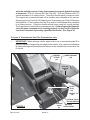
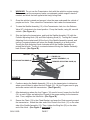
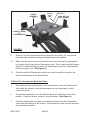
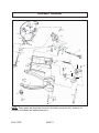
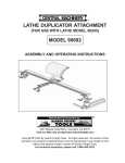
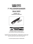
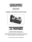
R
TRANSMISSION JACK
1200 LBS. CAPACITY - LOW PROFILE
MODEL 91020
OPERATING INSTRUCTIONS
®
3491 Mission Oaks Blvd., Camarillo, CA 93011
Visit our Web site at http//www.harborfreight.com
Copyright© 2003 by Harbor Freight Tools®. All rights reserved. No portion of this
manual or any artwork contained herein may be reproduced in any shape or form
without the express written consent of Harbor Freight Tools.
For technical questions, please call 1-800-444-3353.
PRODUCT SPECIFICATIONS
Item
Maximum Lifting Capacity
Overall Dimensions
Front & Rear Castors
Saddle Block Dimensions
Saddle Side To Side Tilt
Saddle Forward Tilt
Pump Lever Rotation
Lift Range
Chain Dimensions
Jack Handle Dimensions
Release Method
Weight
Description
1,200 Pounds.
18-1/2” W x 38” L x 32” H (Fully Raised).
18-1/2” W x 38” L x 8” H (Fully Lowered).
Quantity: 4 / Dimensions: 1-1/4” W x 4” H.
9-1/8” W x 9-1/8” L.
12°.
65°.
360°.
5-3/4” (Minimum).
31-1/2” (Maximum).
1/4” Thick x 39” Long.
7/8” Diameter x 24” Long.
Twist Valve Type.
116 Pounds.
SAVE THIS MANUAL
You will need this manual for the safety warnings and precautions, assembly,
operating, inspection, maintenance and cleaning procedures, parts list and assembly
diagram. Keep your invoice with this manual. Write the invoice number on the inside
of the front cover. Keep this manual and invoice in a safe and dry place for future
reference.
UNPACKING
When unpacking, check to make sure all the parts shown in the Parts List on page
10 are included. If any parts are missing or broken, please call Harbor Freight Tools at the
number shown on the cover of this manual as soon as possible.
GENERAL SAFETY WARNINGS AND PRECAUTIONS
1.
Keep work area clean and dry. Cluttered, damp, or wet work areas invite
injuries.
2.
Keep children away from work area. Do not allow children to handle this
product.
SKU 91020
PAGE 2
3.
Store idle equipment. When not in use, tools and equipment should be stored
in a dry location to inhibit rust. Always lock up tools and equipment, and keep out
of reach of children.
4.
Do not use this product if under the influence of alcohol or drugs. Read
warning labels on prescriptions to determine if your judgement or reflexes are
impaired while taking drugs. If there is any doubt, do not attempt to use this
product.
5.
Use eye and hand protection. Wear ANSI approved safety impact eye goggles,
and safety gloves when using this product. ANSI approved safety impact eye
goggles and safety gloves are available from Harbor Freight Tools.
6.
Dress safely. Do not wear loose clothing or jewelry, as they can become caught
in moving parts. Wear a protective hair covering to prevent long hair from becoming caught in moving parts.
7.
Do not overreach. Keep proper footing and balance at all times to prevent
tripping, falling, back injury, etcetera.
8.
Industrial applications must follow OSHA requirements.
9.
Stay alert. Watch what you are doing at all times. Use common sense. Do not
use this product when you are tired or distracted from the job at hand.
10.
Check for damaged parts. Before using this product, carefully check that it will
operate properly and perform its intended function. Check for damaged parts
and any other conditions that may affect the operation of this product. Replace
or repair damaged or worn parts immediately.
11.
Replacement parts and accessories: When servicing, use only
identical replacement parts. Only use accessories intended for use with this
product. Approved accessories are available from Harbor Freight Tools.
12.
Maintain this product with care. Keep this product clean and dry during storage for better and safer performance. For your safety, service and maintenance
should be performed regularly by a qualified technician.
13.
Use the right equipment for the job. Do not attempt to force small equipment
to do the work of larger industrial equipment. There are certain applications for
which this equipment was designed. It will do the job better and more safely at
the rate for which it was intended. Do not modify this equipment, and do not use
this equipment for a purpose for which it was not intended.
14.
WARNING! The warnings, precautions, and instructions discussed in this manual
SKU 91020
PAGE 3
cannot cover all possible conditions and situations that may occur. The operator
must understand that common sense and caution are factors, which cannot be
built into this product, but must be supplied by the operator.
SPECIFIC PRODUCT WARNINGS AND PRECAUTIONS
1.
Do not exceed the maximum lift capacity (1200 pounds) for the Transmission
Jack. Overloading the Transmission Jack could cause personal injury and/or property
damage.
2.
Use of the Transmission Jack is limited to the removal, installation, and
transportation (in the Jack’s lowered position) of transmissions and
differentials within the weight limitation specified. No alteration to the Jack or
adapters shall be made.
3.
Never open or adjust the Bypass Valve. (Noted in Figure A, page 6.) The Bypass
Valve is an essential safety device that is factory-set. Adjusting the Bypass Valve
may cause serious personal injury, property damage, or hinder proper operation of
the Transmission Jack.
4.
Make sure the Transmission Jack is used only on a dry, oil/grease free, solid,
level, concrete surface capable of supporting the weight of the entire vehicle,
Transmission Jack, and any additional tools and equipment.
5.
Prior to using the Transmission Jack, make sure to read and understand all
warnings, safety precautions, and instructions as outlined in the vehicle
manufacturer’s instruction manual.
6.
Do not use the Transmission Jack with the vehicle’s engine running. Also,
make sure to place proper support devices (not included) under the vehicle.
7.
Do not allow anyone in the vehicle while using the Transmission Jack.
Keep all bystanders a safe distance away from the vehicle.
8.
Never leave the Transmission Jack unattended when the Jack is under a load.
9.
Always keep hands, fingers, and feet away from the moving parts of the
Transmission Jack when applying or releasing a load. Remain clear of the
Transmission Jack when raising or lowering a transmission or differential.
10.
Always evaluate your task before using the Transmission Jack. The
Transmission Jack is designed to support a transmission or differential as individual
components. Assemblies such as a differential with an axle, or a transmission with
bell housing, can be bulky and difficult to balance on the Jack’s platform or cradle.
SKU 91020
PAGE 4
Lifting such assemblies, even within the weight limit, can create an o f f - b a l a n c e
situation, causing the Transmission Jack to tip over and lead to serious personal
injury and/or property damage. The load should be evenly distributed on the
Transmission Jack, and should not extend beyond the area of the caster wheelbase.
Always use safety straps and/or chains to secure the load.
11.
If you are working and the load becomes off-balanced and/or the Transmission
Jack begins to tip over, DO NOT attempt to catch or lift the Jack when it is
falling. In this event, clear the area as quickly and safely as possible in order to
avoid injury from the falling load or getting hit with flying fragments.
12.
If in doubt about the safety of your project, it is recommended that you have
the work done by a qualified technician familiar with applicable safe practices.
Do not use the Transmission Jack as a permanent stand for a transmission or
differential. Use the Transmission Jack only while making repairs. Then, immediately
remove the transmission or differential from the Transmission Jack.
13.
14.
Before lowering the Transmission Jack, make sure tools, tool trays, vehicle
parts, and all other equipment are removed from under the Jack.
15.
Maintain labels and nameplates on the Transmission Jack. These carry important
information. If unreadable or missing, contact Harbor Freight Tools for a replacement.
ASSEMBLY AND OPERATING INSTRUCTIONS
NOTE: For additional references to the parts listed in the following pages, refer to the
Assembly Diagram on page 11.
To Assemble The Handle:
1.
Prior to operation, the Handle (36) must be attached to the Transmission Jack.
To do so, loosen the Hex Cap Screw (44) that is located on the Handle Socket
(46). Insert the open end of the Handle fully into the Handle Socket. Then,
firmly retighten the Hex Cap Screw. (See Figure A, next page.)
To Purge The Hydraulic System Of Excess Air:
1.
IMPORTANT! Make sure to thoroughly test the Transmission Jack for
proper operation prior to its actual use. If the Transmission Jack appears
SKU 91020
PAGE 5
not to be working properly, it may be necessary to purge its hydraulic system
of excess air. To do so, remove the Filler Plug (45). Turn the Release Valve (47)
counterclockwise to its open position. Pump the Handle rapidly numerous times.
The trapped air is pressurized and will be audible when released in this manner.
Once purged of air, check the Oil Chamber and, if necessary, top off the Oil Chamber
with hydraulic oil. Then replace the Filler Plug, and turn the Release Valve clockwise
to its closed position. Pump the Handle several times, using full, smooth strokes.
The Transmission Jack should now operate properly. If, after purging, the Hydraulic
Jack still does not appear to be working properly, do not use the Hydraulic
Jack until it has been repaired by a qualified technician. (See Figure A.)
To Lower A Transmission Onto The Transmission Jack:
1.
IMPORTANT! When raising a vehicle, make sure to use a commercial grade lift or
jack fully capable of supporting the weight of the vehicle. Also, read and understand
all safety warnings and precautions as outlined in the manufacturer’s manual for the
lift or jack.
GREASE
FITTING
(33)
HANDLE SOCKET
(46)
HEX CAP
SCREW
(44)
FILLER
PLUG
(45)
HANDLE
(36)
BYPASS VALVE
(DO NOT ADJUST)
RELEASE
RELEASE
VALVE
CHECK
VALVE
(47)
FIGURE A
SKU 91020
PAGE 6
2.
WARNING! Do not use the Transmission Jack with the vehicle’s engine running.
Make sure to set the emergency brake, use adequate vehicle support stands if
needed, and block the tires opposite the tire(s) being lifted.
3.
Once the vehicle is raised and secured, clear the area underneath the vehicle of
people and tools. Then, wheel the Transmission Jack under the transmission.
4.
To raise the Saddle Assembly (12) of the Transmission Jack, turn the Release
Valve (47) clockwise to its closed position. Pump the Handle, using full, smooth
strokes. (See Figure A.)
5.
Stop just below the transmission, and level the Saddle Assembly (12) with the
Forward Adjusting Knob (24) and Side Adjusting Knob (6). Turning the Forward
Adjusting Knob clockwise will lift the front of the Saddle Assembly upward, and
turning it counterclockwise will return the Saddle Assembly to a level position.
Turning the Side Adjusting Knob clockwise will tilt the Saddle Assembly up,
raising the left side. Turning it counterclockwise will bring the Saddle Assembly
back to level. (See Figure B.)
HEX BOLT (14)
FINGER (16)
SADDLE ASSEMBLY (12)
SIDE ADJUSTING KNOB (6)
FORWARD ADJUSTING KNOB (24)
FIGURE B
6.
Continue raising the Saddle Assembly (12) up to the transmission to determine
where you will need to adjust the four Fingers (16). All four Fingers need to grip
and make contact with the transmission. (See Figure B.)
7.
After determining where the four Fingers (16) need to be set, loosen the Hex Bolt
(14) on each Finger and adjust the Fingers to the proper setting for the transmission. Then, retighten the Hex Bolts. (See Figure B.)
8.
Secure the Chain (13) to the Chain Bracket, and wrap the Chain securely around
the transmission. Attach the other end of the Chain to the Hook (17) on the other
side of the Saddle Assembly (12). Then, tighten the Wing Nut (20) on the other
end of the Hook. (See Figure C, next page.)
SKU 91020
PAGE 7
SADDLE
ASSEMBLY
(12)
CONNECT
CHAIN
HERE.
HOOK (17)
WING NUT (20)
(NOT SHOWN)
CONNECT CHAIN
TO
CHAIN BRACKET
FIGURE C
9.
Once you are sure the transmission is secured by the Chain (13), remove the
bolts and other hardware holding the transmission to the chassis.
10.
Make sure the area is clear of people and tools, and verify that the transmission
is securely held in place by the Transmission Jack. Then, slowly turn the Release
Valve (47) counterclockwise to lower the Transmission Jack to its lowest position
before moving the unit. (See Figure A.)
11.
Carefully wheel the Transmission Jack from under the vehicle to perform the
desired maintenance on the transmission.
To Raise The Transmission Back Into Place:
1.
After performing the maintenance on the transmission, move the Transmission
Jack under the vehicle so that the transmission is lined up properly with its
connection points.
2.
To raise the transmission, turn the Release Valve (47) clockwise to its closed
position. Pump the Handle, using full, smooth strokes. (See Figure A.)
3.
Guide the transmission into place, and replace the bolts and other hardware to
secure the transmission to the chassis. Double check to make sure the transmission is securely installed.
SKU 91020
PAGE 8
4.
Loosen the Wing Nut (20) on the Hook (17) to remove one side of the Chain (13).
Move the Chain out of the way, making sure it will not be in the way of the Transmission Jack when it lowers. (See Figure C.)
5.
Make sure nobody is close to the Transmission Jack. Slowly turn the Release
Valve (47) counterclockwise to lower the Transmission Jack to its lowest
position. Then, wheel the Transmission Jack clear of the vehicle.
(See Figure A.)
INSPECTION, MAINTENANCE, AND CLEANING
1.
Before each use, inspect the general condition of the Transmission Jack. Check
for broken or bent parts, loose or missing parts, and any condition that may affect
the proper operation of the product. If a problem occurs, have the problem
corrected before further use. Do not use damaged equipment.
2.
Keep all moving parts of the Transmission Jack well lubricated. Periodically,
lubricate the Grease Fitting (33). (See Figure A.)
3.
Change the hydraulic oil at least once every three years. To do so, with the
Transmission Jack fully collapsed remove the Oil Filler Plug (45) at the top of
the Oil Reservoir. Tip the Transmission Jack to allow the old oil to drain out of
the Reservoir completely, and dispose of the old oil in accordance with local
hazardous waste authority regulations. With Transmission Jack upright, completely fill the reservoir with a high quality hydraulic oil (not included). Then, reinstall the Oil Filler Plug. Make sure to thoroughly test the Transmission Jack
for proper operation prior to its actual use. If the Transmission Jack appears
not to be working properly, it may be necessary to purge its hydraulic
system of excess air. (See instructions on page 5 and Figure A.)
4.
Purge the hydraulic system of air occasionally. Occasionally, the Transmission Jack will exhibit signs of excessive air in its hydraulic system such as slow
response to pumping, a spongy feeling to the pumping operation, and a general
lack of performance. To purge the hydraulic system of air, open the Release
Valve (never more than two turns). Loosen the Oil Filler Plug (45) just enough for
any air to escape. Then, re-tighten the Release Valve, and slowly pump the
Transmission Jack several times. The trapped air is pressurized and will be
audible when released in this manner. Once purged of air, check the Oil Reservoir and, if necessary, top off the Reservoir with hydraulic oil. Then, replace the
Oil Filler Plug, and completely lower the Transmission Jack. Make sure to
thoroughly test the Transmission Jack for proper operation prior to its
actual use. (See Figure A.)
SKU 91020
PAGE 9
PLEASE READ THE FOLLOWING CAREFULLY
THE MANUFACTURER AND/OR DISTRIBUTOR HAS PROVIDED THE PARTS LIST AND
ASSEMBLY DIAGRAM IN THIS MANUAL AS A REFERENCE TOOL ONLY. NEITHER THE
MANUFACTURER OR DISTRIBUTOR MAKES ANY REPRESENTATION OR WARRANTY OF
ANY KIND TO THE BUYER THAT HE OR SHE IS QUALIFIED TO MAKE ANY REPAIRS TO THE
PRODUCT, OR THAT HE OR SHE IS QUALIFIED TO REPLACE ANY PARTS OF THE
PRODUCT. IN FACT, THE MANUFACTURER AND/OR DISTRIBUTOR EXPRESSLY STATES
THAT ALL REPAIRS AND PARTS REPLACEMENTS SHOULD BE UNDERTAKEN BY
CERTIFIED AND LICENSED TECHNICIANS, AND NOT BY THE BUYER. THE BUYER
ASSUMES ALL RISK AND LIABILITY ARISING OUT OF HIS OR HER REPAIRS TO THE
ORIGINAL PRODUCT OR REPLACEMENT PARTS THERETO, OR ARISING OUT OF HIS OR
HER INSTALLATION OF REPLACEMENT PARTS THERETO.
PARTS LIST
Part #
1
2
3
4
5
6
7
8
9
10
11
12
13
14
15
16
17
18
19
20
21
22
23
24
Description
Main Frame
Lift Arm
Lift Arm Strap
Front Link
Snap Ring
Side Adjuster Knob
Spacer
Side Pivot (Front)
Hex Nut
Side Pivot (Back)
Snap Ring
Saddle Assembly
Chain/Bolt Kit
Hex Bolt
Washer
Finger
Hook
Stud
Washer
Wing Nut
Hex Nut
Side Pivot Shaft
Saddle Support Assembly
Forward Adjuster Knob
Qty.
1
1
2
2
8
1
1
1
2
1
4
1
1
8
8
4
1
1
2
1
1
1
1
1
Part #
25
26
27
28
29
30
31
32
33
34
35
36
37
38
39
40
41
42
43
44
45
46
47
Description
Spring Pin
Forward Pivot (Front)
Bearing
Forward Pivot (Back)
Channel Nut
Cotter Pin
Forward Pivot (Shaft)
Return Spring
Grease Fitting
Cotter Pin
Hydraulic Unit
Handle
Lock Washer
Hex Cap Screw
Lift Arm Pivot Pin
Hex Cap Screw
Caster
Washer
Lock Nut
Hex Cap Screw
Filler Plug
Handle Socket
Release Valve
Qty.
2
1
1
1
1
1
1
1
1
1
1
1
4
4
1
16
4
16
16
1
1
1
1
NOTE: Some parts are listed and shown for illustration purposes only, and are not
available individually as replacement parts.
SKU 91020
PAGE 10
ASSEMBLY DIAGRAM
46
45
.
47
NOTE: Some parts are listed and shown for illustration purposes only, and are not
available individually as replacement parts.
SKU 91020
PAGE 11