1
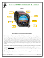
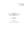
CASTLEBERRY Instruments & Avionics
MODEL 300-14EL
ATTITUDE GYRO
OPERATOR GUIDE
__________________________________________________________________________________________
Document: 0052-1001-0001
Page 1 of 4
Revision B
CASTLEBERRY Instruments & Avionics
Model 300-14EL Operator Guide
General Information
This attitude indicator is a precision gyroscopic instrument that provides the pilot with a visual reference of the
aircraft pitch and roll attitude with respect to earth.
To achieve this desired attitude indication, the gyro establishes and maintains a stabilized datum reference
perpendicular to the earth. This rigidity in space is developed by a gimbal mounted high speed self erecting
rotor that generates enough angular momentum to overcome small frictional forces.
This gyro is electrically operated to provide power for the rotor. The spinning mass rotor provides both the
gyroscopic effect and turns impellers to create air flow to provide the leveling torque to keep gyro perpendicular
to the earth.
This gyro is calibrated for standard rate turns. Turns that are faster will create larger errors in pitch and roll
such that when turn is completed it will require more time for gyro to return to a true vertical position.
A Gyro Flag is controlled by a monitor circuit that indicates the integrity of gyro.
Emergency Procedures
In the event that the Gyro Flag comes into view, the accuracy of the gyro is in question until the flag goes back
out of view and the attitude indication is compared with another attitude reference. This situation should also
prompt the verification of the quality of the gyro power source.
Pre-flight Procedures
During pre-flight procedures the attitude gyro must be provided adequate electrical power with vibration to
simulate normal environmental conditions. This is usually achieved by having engines running.
After observing the Gyro Flag go out of view, initial erection is accomplished by pulling the “Pull For Quick
Erect” knob to cage the gyro while the aircraft is in a level or near level position. After caging the gyro will
quickly settle to true level. In a tail-dragger aircraft the caging operation should not be done until after take-off
in level flight. This knob is spring loaded to return caging mechanism to its normal position.
In-flight Procedures
CAUTION: Caging the gyro by pulling the “Pull For Fast Erect” knob while in flight when the aircraft is not
level will cause the gyro to be incorrect. The Parallax indicator may be adjusted anytime to remove parallax
from pilot’s view.
__________________________________________________________________________________________
Document: 0052-1001-0001
Page 2 of 4
Revision B
CASTLEBERRY Instruments & Avionics
Figure 1
5. Roll Dial
4. Roll Indice
6. Gyro Flag
3. Pitch Dial
7. Inclinometer
2. Parallax
Indicator
1. Parallax
Adjust
8. Caging
Knob
Observe Figure 1 for description of features as follows:
1. Parallax Adjustment Knob is used to set the Parallax Indicator (item 2) reference on the actual gyro horizon
after settling as viewed by the pilot. Aircraft engines should be on during this process to apply nominal
operating voltage to gyro and to generate the required vibration to overcome static friction to simulate a
real operating environment. Normal operation would be to turn gyro on and allow for gyro to spin up till
flag (item 6) hides out of view, then perform a caging operation (explained for item 8) and then allow gyro
a few minutes to settle to level. The gyro is settled when both pitch and roll indications remain constant.
The Parallax may be set on ground when the aircraft is level as it would be in a trimmed straight and level
flight or set in air during straight and level trimmed flight with wingtips and pitch reference on the earth’s
horizon.
At this time the Parallax Adjustment knob should be set so that at the pilots viewing angle of the Parallax
Indicator rests centered on the horizon line of the Pitch Dial (item 3). Once the parallax is set it is
generally not changed again unless the pilot’s seat has moved or a different height pilot requires a different
viewing angle.
2.
This is the Parallax Indicator. Purpose and operation is described in paragraph 1 which is the adjustment
that sets the position of this item.
__________________________________________________________________________________________
Document: 0052-1001-0001
Page 3 of 4
Revision B
CASTLEBERRY Instruments & Avionics
3.
Item 3 is the Pitch Dial. The gyro pitch attitude angle is determined by reading the Pitch Dial position
against the Parallax Indicator (previously set in item 1).
Note: The horizon line on the Pitch Dial may or may not be exactly aligned with the zero indices of the
Roll Dial (item 5) at true level. This can be due to the ± 1½ degree tolerance that is typical for attitude
gyros.
4.
This is the Roll Indice. The roll attitude angle is read by the position of the Roll Dial (item 5) against this
indice.
5.
Roll Dial. See Item 4.
6.
The Gyro Flag is a monitor to determine integrity of gyro. It is controlled by internal circuitry that will
cause the Flag to come into view if input power or gyro RPM becomes too low. Since it is affected by
gyro RPM, the Flag does not go out of view immediately when power is applied. Typically it takes 1 to 3
minutes for the Flag to go out of view and up to 5 minutes if operating with low voltage.
7.
This is the inclinometer. It is a required device when this gyro is installed as a replacement for the turn
indicator gyro per FAA advisory circular AC91-75.
8.
This knob is used for quick erect. Operation of the “Pull For Quick Erect” knob is done by a steady pulling
outward on the knob with a couple pounds of force until the gyro presentation has stopped moving and in a
level indication of both pitch and roll attitude and then gently releasing the knob to return to its spring
loaded position. This operation is called caging. It is normal for the gyro inertia to create or not to create a
tumbling effect during this operation depending upon its position at the time the knob was pulled.
Even though the gyro looks level after caging, it is really only level at this time if the aircraft was perfectly
level when the caging was done. Immediately after caging, the gyro will begin to settle towards true level.
By being somewhat close to level when caging the gyro, it should settle to true level in a short period of
time producing the “Fast Erect” function.
Caution: Caging the gyro by pulling the “Pull For Fast Erect” knob while in flight when the aircraft is not
level will cause the gyro to be incorrect.
__________________________________________________________________________________________
Document: 0052-1001-0001
Page 4 of 4
Revision B