1
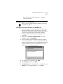
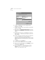
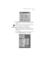
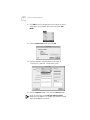
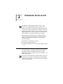
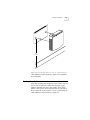
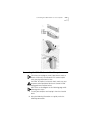
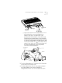
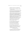
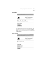
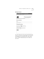
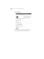
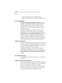
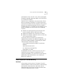
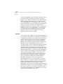
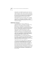
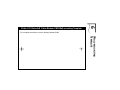
U.S. Robotics® Cable Modem TMX Getting Started Guide http://www.3com.com/ Part No. 10031161 Published February 2000 3Com Corporation 3800 Golf Rd. Rolling Meadows, IL 60008 Copyright © 2000 3Com Corporation. All rights reserved. No part of this documentation may be reproduced in any form or by any means or used to make any derivative work (such as translation, transformation, or adaptation) without written permission from 3Com Corporation. 3Com Corporation reserves the right to revise this documentation and to make changes in content from time to time without obligation on the part of 3Com Corporation to provide notification of such revision or change. 3Com Corporation provides this documentation without warranty of any kind, either express or implied, including, but not limited to, the implied warranties of merchantability and fitness for a particular purpose. 3Com may make improvements or changes in the product(s) and/or the program(s) described in this documentation at any time. If there is any software on removable media described in this documentation, it is furnished under a license agreement included with the product as a separate document, in the hard copy documentation, or on the removable media in a directory file named LICENSE.TXT or !LICENSE.TXT. If you are unable to locate a copy, please contact 3Com and a copy will be provided to you. UNITED STATES GOVERNMENT LEGEND If you are a United States government agency, then this documentation and the software described herein are provided to you subject to the following: All technical data and computer software are commercial in nature and developed solely at private expense. Software is delivered as “Commercial Computer Software” as defined in DFARS 252.227-7014 (June 1995) or as a “commercial item” as defined in FA R2.101(a) and as such is provided with only such rights as are provided in 3Com’s standard commercial license for the Software. Technical data is provided with limited rights only as provided in DFAR 252.227-7015 (Nov 1995) or FAR 52.227-14 (June 1987), whichever is applicable. You agree not to remove or deface any portion of any legend provided on any licensed program or documentation contained in, or delivered to you in conjunction with, this User Guide. 3Com, the 3Com logo, and U.S. Roboticsare registered trademarks and Connections is a trademark of 3Com Corporation. Microsoft, Windows, and Windows NT are registered trademarks of Microsof tCorporation. All other company and product names may be trademarks of the respective companies with which they are associated. CONTENTS 1 BEFORE YOU BEGIN Introduction 1 Cable Modem TMX Features 1 Contacting Your Broadband Service Provider (BSP) 2 Preparing Your Workspace 3 You Will Need These Items 4 Configuring the TCP/IP Protoco l5 Configuring the TCP/IP Protocol on a Windows P C5 Configuring the TCP/IP Protocol on a Macintosh P C7 2 HARDWARE INSTALLATION Wall-Mount Installation 11 Desktop Installation 13 Stacking Installation with OfficeConnect Products Connecting the Cable Modem to Your Computer 14 15 3 CABLE MODEM CONFIGURATION Configuring Non-3Com U.S. Robotics Modems for Use with the TMX 22 Using the Cable Modem TMX 24 Summary of Configuration Software Screens24 Dial/HangUp 25 Rescan Channels 25 Tune Frequency 26 DHCP Configuration 26 Enroll 27 Dial-Up Parameters 28 Dialing Parameters 29 Access Parameters30 DHCP/PPP Parameters 31 Cable Modem Configuration 32 Session Status 33 Message Log 33 Interpreting Your Cable Modem's LED Lights Upgrading to CMX Functionality 35 34 4 TROUBLESHOOTING AND SUPPORT RESOURCES Troubleshooting 37 The analog modem does not dial my cable company’s server properly. 37 My computer went into “power save” mode. When it came out of power save mode, my screen was frozen. 37 I see a delay when loading Web pages or downloading files (Mac users only). 38 I cannot access the 149.112.50.65 URL after disconnecting from my BSP .38 The Cable Status LED never stops blinking. 38 Support Resources 38 If You Are Still Having Problems 38 If You Need to Return the Modem to Us 39 World Wide Web 39 90-Day Free Installation Support 39 Technical Support Hotline 39 5 REGULATORY INFORMATION AND LIMITED WARRANTY Manufacturer’s Declaration of Conformity Caution to the User 41 Performance Specifications 41 Export Notices 41 License Agreement 42 Industry Canada (IC) 42 UL Listing/CUL Listing42 Radio and Television Interference 42 3Com Corporation Limited Warranty 43 Hardware 43 Software 44 Year 2000 Warranty 45 Obtaining Warranty Service 45 WARRANTIES EXCLUSIVE 46 LIMITATION OF LIABILITY 47 Disclaimer 47 41 Governing Law 47 6 WALL-MOUNTING TEMPLATE BEFORE YOU BEGIN 1 Introduction This guide provides all the information you need to use your Cable Modem TMX and an analog modem to dial into one-way Broadband Service Providers (BSPs). Not all cable companies and BSPs provide two-way service. In the event that you have a one-way cable provider or BSP, you need to use an analog modem to send data to the provider, and then receive data from the provider over the cable line using a cable modem like the TMX. BSPs who currently offer one-way service may choose to upgrade to two-way service at some point in the future. Your new Cable Modem TMX is software upgradable to the full operation of the 3Com® U.S. Robotics® Cable Modem CMX. See the chapter in this guide about two-way access for more information. If you purchased the TMX Dialup Kit, the external analog modem required for dialing into your provider is included. If you purchased the TMX modem alone, you will need a compatible external serial analog modem. (This product will not work with an internal or USB-only analog modem.) The diagrams and instructions in this guide assume you have purchased the Dialup Kit. Installation using a modem other than the one included in the Dialup Kit should be very similar to the procedures described in this guide. Consult your analog modem's documentation for more details concerning its operation and setup. Cable Modem TMX Features ■ Downstream user data rates of up to 38 Mbps (megabits per second), faster than 56K analog modems, ISDN, or ADSL 2 CHAPTER 1: BEFORE YOU BEGIN ■ ■ Plug and play operation ensures easy setup and installation 3Com’s extensive user support organizations and our 5-year limited warranty * Please note that the following factors affect the speeds you may experience: ■ Your computer equipment and configuration, including the speed of your processor, the amount of RAM on your system, and your available hard disk space. ■ The Internet browsing, e-mail, or other programs you run at the same time, which use your computer’s resources. ■ The capacity of the Internet service you order from your provider. ■ Changing network traffic levels depending on when you go online. Contacting Your Broadband Service Provider (BSP) In order to use your cable modem, you need to establish an Internet access account with your local BSP. Before contacting your BSP to establish an account, have the following information handy: ■ The modem’s Media Access Control (MAC) address (located on a bar code sticker on the back of the modem). The MAC address consists of 12 characters preceded by the text EA =. In the following example label image, the MAC address is 00104B377410. Write the MAC address in the blank provided below. Preparing Your Workspace ■ 3 The modem’s model number (located on a sticker on the bottom of the modem). MAC address: EA = __________________ Model number: 3CR292B-TR56 You should now contact your BSP and verify the following: ■ ■ ■ You have cable service to your home that supports cable modem access. If your BSP does not provide cable modem access, the 3Com U.S. Robotics Cable Modem TMX will not be able to communicate with your BSP’s Internet access service. Visit the following URL for additional information: http://www.3com.com/cablemodem Your BSP has set up your cable Internet access account. Your BSP will establish an Internet access account that will allow you to send and receive e-mail, access the World Wide Web, and receive other Internet services. This account must be established before you can use your cable modem. You have a cable line near your PC and it has been prepared for cable modem service. If you do not have a cable line in your home that supports cable modem access or if your current cable connection is not conveniently located near your computer, your cable company can install one. If you use your cable line for cable television access, your cable company can also install an additional line for use with your cable modem. Preparing Your Workspace ■ ■ ■ Position your computer so that it is located near your cable outlet. The cable modem should be located near your computer and the cable outlet. There should be plenty of room to guide the cables away from the modem without crimping the cables. The modem should be located where it has ample space to allow constant airflow around the unit. 4 CHAPTER 1: BEFORE YOU BEGIN ■ ■ ■ Do not stack anything on top of the cable modem. (See the instructions on page 14 concerning stacking this modem with 3Com OfficeConnect products.) The temperature in the room where the cable modem will be operating should be between 0 and 40°C (32 and 104°F). Relative humidity should be between 5 and 95%, non-condensing. Familiarize yourself with all of the materials in this box. Please read these installation instructions thoroughly before installing your cable modem. CAUTION: Your cable company will provide a cable connection. Do not attempt any rewiring without first contacting your cable company. You Will Need These Items Included: ■ Cable modem ■ Cable modem power supply ■ Analog modem, power supply, and DB-25 to DB-9 cable (TMX Dialup Kit only) ■ RJ-45 network cable ■ Rubber feet and stacking clips kit ■ This Getting Started Guide Not Included: ■ ■ ■ ■ ■ A PC running Windows 95 operating system (or later) or a Macintosh computer running the System 7.5 operating system (or later) with TCP/IP protocol installed (see the following two sections for more information on installing TCP/IP) An active cable line An active Ethernet port or network interface card (NIC) installed in your computer A 7/16 inch (or adjustable) wrench for securing the cable line to the modem A screwdriver, pushpins, and screws (for optional wall-mounting) The screw heads should be at least 0.2” (5mm) in diameter for them to be properly captured in Configuring the TCP/IP Protocol 5 the slot. If you are using wood screws, use #6 pan heads or equivalent. Configuring the TCP/IP Protocol NOTE: If you are using a Macintosh computer, turn to the instructions on page 7. Configuring the TCP/IP Protocol on a Windows PC You need to make sure that either an active Ethernet port, Ethernet Network Interface Card (NIC), or an active USB port and the TCP/IP communications protocol are installed on your system before you install your cable modem. Configure TCP/IP as described in the following set of instructions. 1 Right-click the Network Neighborhood icon on your desktop and then click Properties. 2 A list of installed network components appears. Look for an entry named “TCP/IP”. This entry may be followed by an arrow and a description of the NIC hardware device or USB network interface installed in your computer. If an entry similar to this is present, go to step 9. . 3 If a similar entry is not present, click Add... 4 Click Protocol, and then click Add... 5 Click Microsoft in the "Manufacturers:" list and then click TCP/IP in the "Network Protocols:" list. Click OK. 6 CHAPTER 1: BEFORE YOU BEGIN 6 "TCP/IP" will appear in the list of installed network components. Click OK. 7 Windows will now ask you if you would like to restart your computer. Click No. 8 Right-click on the Network Neighborhood icon on your desktop then click Properties in the drop-down menu that appears. 9 Double-click the entry in the "Configuration" menu that reads "TCP/IP -->" followed by a description of your NIC or dialup adapter. 10 Click the “Advanced” tab and then make sure the box next to "Set this protocol to be the default protocol." is checked. If it is not, click the box to put a check in it. (If this option is grayed out, then you do not have TCP/IP installed properly.) 11 Click OK and then click OK again. 12 Click the Windows Start button and then click Run. 13 When the “Run” screen appears, type winipcfg in the text field and click the OK button. 14 The "IP Configuration" window will appear. Click the Release button. A line of zeros will appear in the "IP Address" and "Subnet Mask" fields. Configuring the TCP/IP Protocol 7 15 Click the Renew button. Numbers will replace the zeros. Click OK and turn to "Hardware and Software Installation" (page 11). NOTE: The numbers on your screen SHOULD be different than those shown in the following example. Configuring the TCP/IP Protocol on a Macintosh PC You need to make sure that the TCP/IP communications protocol is installed on your system before you install your cable modem. 1 Click the Apple icon in the upper left corner of the Finder. Scroll down to Control Panels, and click TCP/IP. 8 CHAPTER 1: BEFORE YOU BEGIN 2 Click Edit on the Finder (gray bar) at the top of the screen. Scroll down to the bottom of the menu and click User Mode. 3 Click the Advanced button then click OK. 4 Click the Up/Down selector arrows (to the right of “Connect Via”) and click "Using DHCP Server". 5 Click the Options button. Then click the Active button. NOTE: In some cases, the Load only when needed button will not appear. If it is visible, click the box. A check mark should appear in the box. Configuring the TCP/IP Protocol 9 6 Verify that the “Use 802.3” box is unchecked (circled in the following image). If there is a check mark in the box, click it to remove the check mark. Then click the Info button in the lower left corner. 7 Ensure there is a Hardware Address listed in this window. If there is, click the OK button and close the “TCP/IP Control Panel” (click File and scroll down to click Close). If there is no Hardware Address, you must shut down and power off your computer. With the power off, simultaneously depress and hold down the Command (Apple), Option, P, and R keys on your keyboard. Keeping those keys depressed, power on the Macintosh computer. The machine will start and you will hear the Apple chime. Keep these keys depressed for up to 3 chimes, then release the keys and allow the computer to start-up. When fully rebooted, ensure that all TCP/IP settings match those in the preceding instructions. If your computer still does not have a 10 CHAPTER 1: BEFORE YOU BEGIN Hardware Address, please contact your local Apple authorized dealer or Apple support. HARDWARE INSTALLATION 2 NOTE: Before installing your modem, write its serial number in the space provided on the first page of this manual. (You’ll find the serial number above the bar code on the white sticker on the back of the modem and on the outside of the modem’s box.) If you ever call our customer support department, a representative will ask you for the serial number. This will help to identify your modem. Before you begin installing the cable modem hardware, you need to determine how you want to incorporate the modem into your work environment. There are three installation options: ■ ■ ■ Wall-mount installation (this page) Desktop installation (page 13) Stacking installation with OfficeConnect products (page 14) Wall-Mount Installation Your cable modem is capable of being wall-mounted, if you choose to do so. The bottom panel of the cable modem has two raised brackets with slots as shown in the following illustration. NOTE: Before wall-mounting the cable modem, follow the instructions in the section “Connecting the Cable Modem to Your Computer” (pages 15-19). Then return to this point to continue the process. CHAPTER 2: HARDWARE INSTALLATION ® 12 mounting holes These slots fit over the heads of wall-mounting screws to secure the modem to the wall. 1 Remove the mounting template from this Guide. 2 Place the mounting template against the wall at the location chosen for the cable modem. The template should be parallel to and at least 20 inches (50 cm) from the floor. Insert pushpins through the template cross hairs into the wall to mark the locations for the screws. 3 Secure the mounting screws into the wall. Do not drive the screws flush to the wall. The screw head should be at least ¼” (6 mm) away from the wall so it can lock into the slots on the modem’s case. 4 Fit the slots in the brackets on the modem’s underside over the screw heads and let the modem slide down into position. Desktop Installation 13 EM OD L AB IN NT NS R FO LL WA TIO U -MO ide ns. s Gu r' te ctio pla stru e Use Tem ic in th ting bas see oun e for tions, -m id c ll Wa ther s instru te eo Se mple co For C RU EM C HE GT ce. ren efe &R T INS ® 20" [ 50 cm ] If you have not already done so, turn to “Connecting the Cable Modem to Your Computer” (page 15) to complete your installation. Desktop Installation If you plan to place your modem on a flat surface, you can use the four self-adhesive rubber feet included in your modem’s package to prevent your modem from sliding around. Stick the feet to the marked areas at each corner of the underside of your modem. Turn to “Connecting the Cable Modem to Your Computer” (page 15). 14 CHAPTER 2: HARDWARE INSTALLATION Stacking Installation with OfficeConnect Products If you own 3Com OfficeConnect products, you can use the four stacking clips included in your modem’s package to neatly and securely stack your cable modem with the OfficeConnect unit(s). If possible, your cable modem should always be the top unit in a stack with OfficeConnect products. Small hubs are the only units that should be clipped to the top of a cable modem. Follow these instructions to clip your modem to an OfficeConnect unit. 1 Place the OfficeConnect device you want at the bottom of the stack on a flat surface. The supplied blue clips fit in the positions on the side of the unit as shown in step 1 of the illustration on the next page. 2 Position a clip over one of these holes and push it in until it clicks into place, as shown in step 2 of the illustration on the next page. Repeat this for the other clip position on the same side. 3 Keeping the front of the units aligned, position the top-most OfficeConnect device and rest the bottom of the device on the clips' spikes, as shown in step 3 of the illustration on the next page. Push the clips firmly until they click into place. NOTE: To remove a clip, hold the units firmly with one hand and hook the first finger of your other hand around the back of the clip. Be careful not to pull so hard that you break the clip. 4 Repeat these steps to secure the other side. 5 Turn to “Connecting the Cable Modem to Your Computer” (page 15). Connecting the Cable Modem to Your Computer 15 Connecting the Cable Modem to Your Computer TIP: Before you unplug any cords, label them or make a sketch of how they are connected. This can be helpful when you plug them back in later. CAUTION: To avoid risk of electric shock, make sure your computer and all peripheral devices are turned off and unplugged from electrical outlets. NOTE: Refer to the diagram on the following page while following these steps. 1 Turn off your computer and unplug it from the electrical outlet. 2 Using the following illustrations as a guide, make the following connections: 16 CHAPTER 2: HARDWARE INSTALLATION ■ ■ Connect your cable line to the cable modem’s CATV cable connector. Be careful not to bend the wire in the center of the cable line when you connect it to the cable modem. After hand-tightening the CATV cable connector, use your 7/16 inch or adjustable wrench to firmly tighten the connector. Be careful not to over-tighten the connector or you might damage the connector or your cable modem. Plug the cable modem’s power supply into a wall socket or surge protector and into the cable modem’s power jack (labeled with a graphic that looks like this: ). Plug one end of the RJ-45 network cable into the cable modem’s RJ-45 jack and the other end into the existing network interface card installed in your computer. - ■ + 10 BT SERIA L CATV power supply (to wall outlet) cable line (to cable outlet) ■ ■ RJ-45 cable RJ-45 Cable (to NIC) Plug the included RS-232 connector cable to the serial port on your cable modem and to the serial port on your analog modem. Plug the analog modem’s power supply into the modem and into a wall socket or surge protector. Connecting the Cable Modem to Your Computer to an analog phone jack ■ 17 to an electrical outlet to a telephone to serial jack on the cable modem Plug a phone cord into the analog modem’s TELCO jack (marked with a on the bottom of the modem’s case) and a wall phone jack. If you purchased the TMX Dialup Kit, use the phone cord included with the analog modem. If you would like to use a phone on the same wall jack you intend to use with the analog modem, plug your phone’s cord into the jack marked with a on the bottom of the modem’s case. When you are finished making all of the necessary connections, your setup should resemble the following diagram. power supply cable (to wall outlet) phone outlet RJ-45 cable (to NIC) tics U.S. Robo cable outlet RS-232 cable 13 2 12 3 11 4 10 5 9 6 8 7 15 25 85 30 80 45 75 50 70 55 65 60 ics Robot 3Com U.S.Modem CMX Cable power supply cable (to wall outlet) Cable Modem Power Status PC Link Status Activit Cable y Activit y Com FCN 3 Turn the analog modem on. The power switch is located on the top front of the modem’s case. 4 Turn your computer on. You are now ready to configure your Cable Modem TMX using our Web-based configuration software. See the next chapter for details. 18 CHAPTER 2: HARDWARE INSTALLATION 3 CABLE MODEM CONFIGURATION The first time you use your Cable Modem TMX, you must configure it using our Web-based configuration software. NOTE: If you do not currently have a Web browser installed on your computer, you can find the two most popular browsers, Netscape Navigator and Microsoft’s Internet Explorer, on the Cable ConnectionsTM CD-ROM included with your kit. 1 Open your Web browser and click on your home or start-up page, which you should have set as the following URL in the "Before You Begin" section of this manual: http://149.112.50.65 2 The “Configuration Screens” menu is the first that appears. Click Enroll. 3 On the "Enroll" screen, highlight your BSP in the drop-down menu that appears and click Show. 20 CHAPTER 3: CABLE MODEM CONFIGURATION 21 4 This brings up the “Dial-Up Parameters screen”. Click Dialing Information. 5 Fill in the "Dialing Information" fields with the information that should have been already provided to you by your BSP. When you are finished entering the information, click Submit. 22 CHAPTER 3: CABLE MODEM CONFIGURATION If you are using a 3Com U.S. Robotics external analog modem in conjunction with your Cable Modem TMX, turn to "Using the Cable Modem TMX" on page 24. Otherwise, see the following section for information about configuring non-3Com U.S. Robotics modems. Configuring Non-3Com U.S. Robotics Modems for Use with the TMX The TMX cable modem is designed to work with a variety of external V.34 modems. If you're using an external modem other then a 3Com U.S. Robotics external modem, please verify that your modem meets these minimum requirements. ■ Modem must be AT command set addressable ■ Modem must support theV.34, V.34bis, orV.90 standard Configuring Non-3Com U.S. Robotics Modems for Use with the TMX ■ ■ ■ 23 Modem must have an RS-232 standard interface Modem’s serial port rate must support 115.2 Kbps Modem’s serial port must be configurable to support hardware flow control If your modem meets these minimum requirements, it may be used with the TMX cable modem, but please remember that the quality of your external analog modem directly effects the performance of your cable connection. In addition to meeting the basic requirements, your analog modem may need to be configured to work properly with the TMX cable modem. The included configuration software provides a "Cable Modem Configuration" screen which can be used to pass additional parameters to your analog modem. These parameters are AT command strings used during initialization. Since the parameters are often manufacturer specific, list below is the optimal configuration. The characters in brackets are the equivalent 3Com U.S. Robotics modem commands. Please refer to your analog modem's user manual for the exact AT commands. It is not necessary to enter AT into the parameter field, only the command parameter. ■ ■ ■ ■ ■ ■ ■ ■ Return result codes in words [V] Serial port rate higher than connect rate [&B1] Transmit data Hardware flow control [&H1] Receive data Hardware flow control [&R2] Auto enable V.42 Error correction [&M4] Auto enable V.42bis data compression [&K1] ITU-T (formerly CCITT) answer sequence [B0] Carrier Detect follows connection (&C1) For example, in order to program your analog modem as described by these commands, you would enter the following string into the "Use User Initial" field on the "Cable Modem Configuration" screen: V&B1&H1&R2&M4&K1B0&C1 Since the quality of analog modems and telephone lines varies greatly, in most cases V.42 error correction and V.42bis data compression should be used. In other 24 CHAPTER 3: CABLE MODEM CONFIGURATION situations, where the analog modem and telephone line quality are both satisfactory, you can disable V.42 error correction and V.42bis data compression. Disabling V.42 error correction and V.42bis data compression while using a quality analog modem on a quality telephone line can improve analog response time and thereby improve your data throughput. After you have configured your modem with these parameters, you should be ready to connect to your cable data service provider. Using the Cable Modem TMX You are now ready to point your browser at any site you wish or launch your Internet software. As soon as you initiate Web-based activity, the Cable Modem should dial out to your BSP's server and establish your connection. This should happen every time you start your computer now that you have configured your TMX. Some Internet applications may produce a “time out” error while waiting for your connection to be established. This is normal. Once you’ve established a connection, refresh or restart your Internet software. See page 34 for information about interpreting the LEDs on the front of your TMX. Summary of Configuration Software Screens The following is a brief summary of the screens you can access from the main menu and how they can help you configure your cable modem and your connection. Summary of Configuration Software Screens 25 Dial/HangUp If you would like to hang up the current connection, you can do so by accessing this menu and clicking HangUp Phone. Once you are ready to establish a new connection, click Dial Phone. Rescan Channels 26 CHAPTER 3: CABLE MODEM CONFIGURATION This menu allows you to manually start a scan for an open channel by clicking the Scan Now button. This is useful if for some reason the cable modem is not currently locked on to an active signal. Tune Frequency This screen allows you to tune the cable modem to an exact frequency. Type the frequency you want to tune to in the “Frequency (Hz)” box and then click Tune Now to set the modem to that frequency. DHCP Configuration Summary of Configuration Software Screens 27 This screen allows you to select options for detecting/selecting source IP addresses for out-bound DHCP packets. Choose your method of detection and then click Submit. Enroll Access this screen to enroll into a new cable modem access account with a Broadband Service Provider (BSP). 28 CHAPTER 3: CABLE MODEM CONFIGURATION Dial-Up Parameters This screen provides links to screens which allow you to modify the dial-up parameters for your cable modem. Here’s an overview of these screens. Summary of Configuration Software Screens 29 Dialing Parameters This screen allows you to enter primary and backup phone numbers into which your analog modem can dial to access your Broadband Service Provider’s (BSP’s) cable modem service. Your BSP should provide you with numbers for these fields. 30 CHAPTER 3: CABLE MODEM CONFIGURATION Access Parameters This screen allows you to modify your account’s login name, password, and radius realm information. Summary of Configuration Software Screens 31 DHCP/PPP Parameters Here you can view your curent provider information, select authentication and server IP address, and set PPP authentication to PAP only, CHAP only, or a negotiated setting. 32 CHAPTER 3: CABLE MODEM CONFIGURATION Cable Modem Configuration This screen displays information concerning your cable modem’s configuration and allows you to edit your user initial. Summary of Configuration Software Screens Session Status This option displays information concerning your cable modem’s current connection. Message Log 33 34 CHAPTER 3: CABLE MODEM CONFIGURATION The Message Log documents the events of each cale modem session (establishing connections, failures to connect, file transfers, etc.). In Internet Explorer, a new window opens to capture activity reports and in Netscape Navigator, the browser creates and saves an HTML file containing the information. The information generatied by the Message Log can be helpful if you need to troubleshoot problems with our technical support staff. Click Refresh to show the messages generated since the last time the screen was accessed. Click Clear Log to delete all existing messages. Click Start Log Capture to open a new browser window that monitors generated messages in real time. The Message Log will continue to show generated messages until you click Stop Log Capture. This option is helpful for analyzing a specific period of time during a given connection when troubleshooting problems. Interpreting Your Cable Modem's LED Lights Here’s a quick overview of the LED lights on the front panel of your modem and what they can tell you about the performance of your modem and the condition of your connection. cs Roboti U.S. dem CMX 3Co Com bl e Mo Ca PC Lin Cable Modem Power 1 Status 2 Cable k Activity Status 3 4 Activity 5 FCN 6 1 Cable Modem Power - Indicates power is applied to the cable modem. This light is solid green when the modem is on. 2 Cable Modem Status - This LED varies in color (orange and green) and indicates the modem’s status as described in the following chart: Upgrading to CMX Functionality 35 LED STATE REPEATING DESCRIPTION SHORT OFF, LONG ORANGE YES Startup, power on self test ORANGE NO Failed power on self test SHORT OFF, SHORT ORANGE YES Downstream hunt LONG ORANGE, SHORT GREEN YES Acquisition in process SHORT OFF, SHORT GREEN YES Offline/not authorized for service GREEN NO Fully operational state 3 PC Link Status - Indicates that the cable modem is connected to the Ethernet card in your computer. This light is solid green when this link is established and your computer is on. 4 PC Link Activity - Indicates that data is being transmitted to or from your PC over the Ethernet port. Flashing orange indicates traffic. This LED should blink when data is being transmitted or received over the Ethernet port. Upgrading to CMX Functionality If your BSP decides to upgrade their service to two-way functionality, they may automatically upgrade your TMX to CMX functionality. You will be alerted if this happens. In this even, you will want to download our 3Com U.S. Robotics Cable Modem CMX documentation at: http://consumer.3com.com/cable 36 CHAPTER 3: CABLE MODEM CONFIGURATION 4 TROUBLESHOOTING AND SUPPORT RESOURCES Troubleshooting The analog modem does not dial my cable company’s server properly. ■ Make sure that the power supplies for both the analog modem and the TMX are plugged into electrical outlets and make sure the analog modem is turned on. ■ Make sure your phone line is active. Plug a telephone into the analog phone jack and listen for a dial tone. ■ Make sure there are no devices between the analog modem and the phone jack. ■ If you have voice mail, there may be messages waiting for you, altering the dial tone. Answer any messages to return the dial tone to normal. ■ Make sure you are dialing the correct access number for your cable company’s cable modem service. ■ Make sure the telephone cord is plugged into the analog modem you have connected to the TMX. My computer went into “power save” mode. When it came out of power save mode, my screen was frozen. If the upstream (analog modem) connection is active when a computer goes into power save mode, the computer may freeze when coming out of power save mode. Either hang up the analog modem before your computer goes into power save mode or disable power save on your PC. If you choose to disable power save, disable it in both the Windows 95 Control Panel and the BIOS setup. To disable power save in Windows 95, click Windows 95 Start, point to Settings, and click Control Panel. Double-click the Power icon and select OFF in the “Power Management” box. Click Apply. To disable power save in the BIOS setup, you usually must press a function key while booting up to 38 CHAPTER 4: TROUBLESHOOTING AND SUPPORT RESOURCES enter the setup menu. Consult you computer’s manual for exact instructions. I see a delay when loading Web pages or downloading files (Mac users only). ■ Close your Internet software and restart it. ■ If you are attempting to access a Web page, refresh or reload the page you are trying to access in your browser. I cannot access the 149.112.50.65 URL after disconnecting from my BSP. You may need to renew your DHCP lease. WINDOWS USERS: Click Start, click Run, type winipcfg, and press ENTER. Select the NIC card that your cable modem is plugged into in the drop down menu that appears. Click Release and then click Renew. Exit out of the "IP Configuration" window and attempt to access the 149.112.50.65 URL again. IMAC AND LINUX USERS: Restart your computer or wait for your current DHCP lease to expire. The Cable Status LED never stops blinking. The signal from your cable company's equipment may be too weak or the cable line may not be properly attached to the modem. If the cable line is properly connected to the modem, call your cable company to verify whether or not a weak signal may be your problem. Support Resources If You Are Still Having Problems ■ Review this manual. ■ Call or visit your modem dealer. They may be able to assist you. ■ If your dealer can't help you, contact 3Com Technical Support. When you call, specify your modem's serial number (found on the modem and on the outside of the box) and the software being used. Support Resources 39 If You Need to Return the Modem to Us Contact 3Com Technical Support. If the support representative determines that you need to return the modem, you will receive a USO (User Service Order) number. You must have a USO number before returning the modem to us. Ship the unit, postage paid, in a strong box made of corrugated cardboard with plenty of packing material. DO NOT send the modem back in the original box. Send ONLY the modem (NOT manuals, diskettes, CDs, etc.). Include your USO number, name, and address on the shipping label as well as inside the package. If possible, send the package via a courier capable of tracking the progress of the shipment. Ship to the following address: 3Com USO #________ Dock 15 1800 W. Central Ave. Mount Prospect, IL 60056 World Wide Web To visit our online support home page, log on to: http://consumer.3com.com/cable/ You can send a message to technical support by clicking Contact Us in the “Site Tools” section of this Web site. 90-Day Free Installation Support 3Com offers free installation support for this product 90 days after purchase. Please call the following toll-free number. 888-877-5040 After the 90-day period, refer to our regular Technical Support Hotline (below). Technical Support Hotline Technical questions about 3Com cable modems can also be answered by technical support representatives. Regular telephone charges apply. The hours service is available are 7:00 AM - 11:00 PM CST seven days a week. 847-262-2550 40 CHAPTER 4: TROUBLESHOOTING AND SUPPORT RESOURCES 5 REGULATORY INFORMATION AND LIMITED WARRANTY Manufacturer’s Declaration of Conformity 3Com 3800 Golf Road Rolling Meadows, IL 60008 U.S.A. declares that the product 3Com U.S. Robotics Cable Modem TMX conforms to the FCC’s specifications: Part 15 Operation is subject to the following two conditions: 1 this device may not cause harmful electromagnetic interference, and 2 this device must accept any interference received including interference that may cause undesired operations. Caution to the User The user is cautioned that any changes or modifications not expressly approved by the party responsible for compliance could void the user’s authority to operate the equipment. Performance Specifications This equipment has a bit-error rate (BER) less than 10-8 when the signal-to-noise ratio (SNR) is 23.5 dB or greater when operating in 64 QAM mode, and when the SNR is 30.0 dB or greater when operating in 256 QAM mode. Export Notices ■ Unlawful to export from the US or Canada without an approved US Department of Commerce export license. ■ The hardware contained in this product contains encryption software which may not be exported or 42 CHAPTER 5: REGULATORY INFORMATION AND LIMITED WARRANTY transferred from the US or Canada without an approved US Department of Commerce export license. License Agreement You agree that you will not export or re-export the Software or accompanying documentation (or any copies thereof) or any products utilizing the Software or such documentation in violation of any applicable laws or regulations of the United States or the country in which you obtained them. The software covered by this agreement may contain strong data encryption code that cannot be exported outside of the U.S. or Canada. You agree that you will not export/reexport, either physically or electronically, the encryption software or accompanying documentation (or copies thereof) or any products utilizing the encryption software or such documentation without obtaining written authorization from the U.S. Department of Commerce. Industry Canada (IC) This digital apparatus does not exceed the Class B limits for radio noise emissions from digital apparatus set out in the interference-causing equipment standard entitled Digital Apparatus, ICES-003 of Industry Canada. Cet appareil numérique respecte les limites de bruits radioélectriques applicables aux appareils numériques de Classe B préscrites dans la norme sur le matériel brouilleur: Appareils Numériques, NMB-003 édictée par l'Industrie Canada. UL Listing/CUL Listing This product is UL and CUL listed for the uses described in this manual. Radio and Television Interference This equipment generates and uses radio frequency energy and if not installed and used properly, in strict accordance with the manufacturer’s instructions, may cause interference to radio and television reception. This device has been tested and found to comply with the limits for a Class B computing device in accordance with the 3Com Corporation Limited Warranty 43 specifications in Part 15 of FCC rules, which are designed to provide reasonable protection against such interference in a residential installation. However, there is no guarantee that interference will not occur in a particular installation. If this device does cause interference to radio or television reception, which you can determine by monitoring reception when the modem is installed and when it is removed from the computer, try to correct the problem with one or more of the following measures: ■ ■ ■ Reorient the receiving antenna (for televisions with antenna reception only) or cable input device. Relocate the computer with respect to the receiver. Relocate the computer and/or the receiver so that they are on separate branch circuits. If necessary, consult your dealer or an experienced radio/television technician for additional suggestions. You may find the following booklet, prepared by the Federal Communications Commission, helpful: How to Identify and Resolve Radio-TV Interference Problems Stock No. 004-000-0345-4 U.S. Government Printing Office Washington, DC 20402 In accordance with Part 15 of the FCC rules, the user is cautioned that any changes or modifications to the equipment described in this manual that are not expressly approved by 3Com could void the user’s authority to operate the equipment. 3Com Corporation Limited Warranty Hardware 3Com warrants to the end user (“Customer”) that this hardware product will be free from defects in workmanship and materials, under normal use and service, for the following length of time from the date of purchase from 3Com or its authorized reseller: 5 years. 44 CHAPTER 5: REGULATORY INFORMATION AND LIMITED WARRANTY 3Com’s sole obligation under this express warranty shall be, at 3Com’s option and expense, to repair the defective product or part, deliver to Customer an equivalent product or part to replace the defective item, or if neither of the two foregoing options is reasonably available, 3Com may, in its sole discretion, refund to Customer the purchase price paid for the defective product. All products that are replaced will become the property of 3Com. Replacement products may be new or reconditioned. 3Com warrants any replaced or repaired product or part for ninety (90) days from shipment, or the remainder of the initial warranty period, whichever is longer. Software 3Com warrants to Customer that each software program licensed from it will perform in substantial conformance to its program specifications, for a period of ninety (90) days from the date of purchase from 3Com or its authorized reseller. 3Com warrants the media containing software against failure during the warranty period. No updates are provided. 3Com's sole obligation under this express warranty shall be, at 3Com's option and expense, to refund the purchase price paid by Customer for any defective software product, or to replace any defective media with software which substantially conforms to applicable 3Com published specifications. Customer assumes responsibility for the selection of the appropriate applications program and associated reference materials. 3Com makes no warranty or representation that its software products will meet Customer’s requirements or work in combination with any hardware or applications software products provided by third parties, that the operation of the software products will be uninterrupted or error free, or that all defects in the software products will be corrected. For any third party products listed in the 3Com software product documentation or specifications as being compatible, 3Com will make reasonable efforts to provide compatibility, except where the non-compatibility is caused by a "bug" or defect in the third party's product or from use of the software product not in accordance with 3Com’s published specifications or user manual. 3Com Corporation Limited Warranty 45 THIS 3COM PRODUCT MAY INCLUDE OR BE BUNDLED WITH THIRD PARTY SOFTWARE, THE USE OF WHICH IS GOVERNED BY A SEPARATE END USER LICENSE AGREEMENT. THIS 3COM WARRANTY DOES NOT APPLY TO SUCH THIRD PARTY SOFTWARE. FOR THE APPLICABLE WARRANTY, PLEASE REFER TO THE END USER LICENSE AGREEMENT GOVERNING THE USE OF SUCH SOFTWARE. Year 2000 Warranty In addition to the Hardware Warranty stated above, 3Com warrants that each product sold or licensed to Customer on and after January 1, 1998 that is date sensitive will continue performing properly with regard to such date data on and after January 1, 2000, provided that all other products used by Customer in connection or combination with the 3Com product, including hardware, software, and firmware, accurately exchange date data with the 3Com product, with the exception of those products identified at 3Com's Web site, http://www.3com.com/products/yr2000.html as not meeting this standard. If it appears that any product that is stated to meet this standard does not perform properly with regard to such date data on and after January 1, 2000, and Customer notifies 3Com before the later of April 1, 2000, or ninety (90) days after purchase of the product from 3Com or its authorized reseller, 3Com shall, at its option and expense, provide a software update which would effect the proper performance of such product, repair such product, deliver to Customer an equivalent product to replace such product, or if none of the foregoing is feasible, refund to Customer the purchase price paid for such product. Any software update or replaced or repaired product will carry a Year 2000 Warranty for ninety (90) days after purchase or until April 1, 2000, whichever is later. Obtaining Warranty Service Customer must contact a 3Com Corporate Service Center or an Authorized 3Com Service Center within the applicable warranty period to obtain warranty service 46 CHAPTER 5: REGULATORY INFORMATION AND LIMITED WARRANTY authorization. Dated proof of purchase from 3Com or its authorized reseller may be required. Products returned to 3Com's Corporate Service Center must be pre-authorized by 3Com with a User Service Order (USO) number marked on the outside of the package, and sent prepaid and packaged appropriately for safe shipment, and it is recommended that they be insured or sent by a method that provides for tracking of the package. The repaired or replaced item will be shipped to Customer, at 3Com's expense, not later than thirty (30) days after 3Com receives the defective product. WARRANTIES EXCLUSIVE IF A 3COM PRODUCT DOES NOT OPERATE AS WARRANTED ABOVE, CUSTOMER'S SOLE REMEDY FOR BREACH OF THAT WARRANTY SHALL BE REPAIR, REPLACEMENT, OR REFUND OF THE PURCHASE PRICE PAID, AT 3COM'S OPTION. TO THE FULL EXTENT ALLOWED BY LAW, THE FOREGOING WARRANTIES AND REMEDIES ARE EXCLUSIVE AND ARE IN LIEU OF ALL OTHER WARRANTIES, TERMS, OR CONDITIONS, EXPRESS OR IMPLIED, EITHER IN FACT OR BY OPERATION OF LAW, STATUTORY OR OTHERWISE, INCLUDING WARRANTIES, TERMS, OR CONDITIONS OF MERCHANTABILITY, FITNESS FOR A PARTICULAR PURPOSE, SATISFACTORY QUALITY, CORRESPONDENCE WITH DESCRIPTION, AND NON-INFRINGEMENT, ALL OF WHICH ARE EXPRESSLY DISCLAIMED. 3COM NEITHER ASSUMES NOR AUTHORIZES ANY OTHER PERSON TO ASSUME FOR IT ANY OTHER LIABILITY IN CONNECTION WITH THE SALE, INSTALLATION, MAINTENANCE OR USE OF ITS PRODUCTS. 3COM SHALL NOT BE LIABLE UNDER THIS WARRANTY IF ITS TESTING AND EXAMINATION DISCLOSE THAT THE ALLEGED DEFECT OR MALFUNCTION IN THE PRODUCT DOES NOT EXIST OR WAS CAUSED BY CUSTOMER'S OR ANY THIRD PERSON'S MISUSE, NEGLECT, IMPROPER INSTALLATION OR TESTING, UNAUTHORIZED ATTEMPTS TO OPEN, REPAIR OR MODIFY THE PRODUCT, OR ANY OTHER CAUSE BEYOND THE RANGE OF THE INTENDED USE, OR BY ACCIDENT, FIRE, LIGHTNING, OTHER HAZARDS, OR ACTS OF GOD. 3Com Corporation Limited Warranty 47 LIMITATION OF LIABILITY TO THE FULL EXTENT ALLOWED BY LAW, 3COM ALSO EXCLUDES FOR ITSELF AND ITS SUPPLIERS ANY LIABILITY, WHETHER BASED IN CONTRACT OR TORT (INCLUDING NEGLIGENCE), FOR INCIDENTAL, CONSEQUENTIAL, INDIRECT, SPECIAL, OR PUNITIVE DAMAGES OF ANY KIND, OR FOR LOSS OF REVENUE OR PROFITS, LOSS OF BUSINESS, LOSS OF INFORMATION OR DATA, OR OTHER FINANCIAL LOSS ARISING OUT OF OR IN CONNECTION WITH THE SALE, INSTALLATION, MAINTENANCE, USE, PERFORMANCE, FAILURE, OR INTERRUPTION OF ITS PRODUCTS, EVEN IF 3COM OR ITS AUTHORIZED RESELLER HAS BEEN ADVISED OF THE POSSIBILITY OF SUCH DAMAGES, AND LIMITS ITS LIABILITY TO REPAIR, REPLACEMENT, OR REFUND OF THE PURCHASE PRICE PAID, AT 3COM'S OPTION. THIS DISCLAIMER OF LIABILITY FOR DAMAGES WILL NOT BE AFFECTED IF ANY REMEDY PROVIDED HEREIN SHALL FAIL OF ITS ESSENTIAL PURPOSE. Disclaimer Some countries, states, or provinces do not allow the exclusion or limitation of implied warranties or the limitation of incidental or consequential damages for certain products supplied to consumers, or the limitation of liability for personal injury, so the above limitations and exclusions may be limited in their application to you. When the implied warranties are not allowed to be excluded in their entirety, they will be limited to the duration of the applicable written warranty. This warranty gives you specific legal rights which may vary depending on local law. Governing Law This Limited Warranty shall be governed by the laws of the State of California, U.S.A. excluding its conflicts of laws principles and excluding the United Nations Convention on Contracts for the International Sale of Goods. 48 CHAPTER 5: REGULATORY INFORMATION AND LIMITED WARRANTY 6 3Com U.S. Robotics Cable Modem CMX Wall-mounting Template For complete instructions, see the Getting Started Guide. WALL-MOUNTING TEMPLATE 50 CHAPTER 6: WALL-MOUNTING TEMPLATE