1
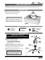
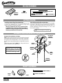
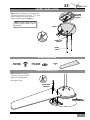
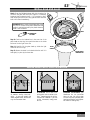
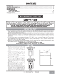
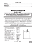
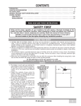
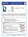
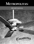
S3 OWNERS MANUAL CONTENTS INTRODUCTION . . . . . . . . . . . . . . . . . . . . . . . . . . . . . . . . . . . . . . . . . . . . . . . . . . . . . . . . . . . . . . . . . . . . . . 1 MOUNTING RECOMMENDATIONS . . . . . . . . . . . . . . . . . . . . . . . . . . . . . . . . . . . . . . . . . . . . . . . . . . . . . . . . . . 2 FAN INSTALLATION . . . . . . . . . . . . . . . . . . . . . . . . . . . . . . . . . . . . . . . . . . . . . . . . . . . . . . . . . . . . . . . . . . . 3 CONTROL FEATURES: VERSA•TOUCH OPERATION . . . . . . . . . . . . . . . . . . . . . . . . . . . . . . . . . . . . . . . . . . . . . . . . . . . . . . . . . . 9 TROUBLESHOOTING . . . . . . . . . . . . . . . . . . . . . . . . . . . . . . . . . . . . . . . . . . . . . . . . . . . . . . . . . . . . . . . . . . . 10 READ AND SAVE THESE INSTRUCTIONS SAFETY FIRST Safety and the proper operation of your Casablanca fan both require a thorough knowledge of the product and proper installation; therefore, before attempting to install and operate your Casablanca fan, read this owner’s manual completely and carefully. Retain this manual for future reference. CAUTION: To avoid possible electrical shock, make certain that electricity is turned off at the circuit breaker or fuse box before attempting any installation procedure. BEFORE YOU START • All wiring must be in accordance with the National Electric Code ANSI/NFPA 70-1993 and the appropriate local electrical codes. The National Electric Code requires proper grounding as a precaution against electrical shock. A qualified electrician should be consulted if you are unsure. • This fan is designed to be installed on an existing electrical outlet box. The outlet box must be UL Listed for ceiling fan installations, if it is not, a new box must be installed. Casablanca extension poles are available for sloped or high ceiling installations. • This ceiling fan requires a grounded electrical supply of 120 VAC, 60 Hz and a minimum 15 amp circuit. The maximum current requirement for the fan with light fixture is 3.8 amps. The fan uses about 1 amp or 100 watts. Maximum light current is 2.8 amps or 340 watts of lighting. • Where wire nuts are employed, be sure all bare wires are within the connectors. When installing the canopy hatch, make sure all wires are within the canopy and that no wires are being pinched. For best performance and for your warranty to be valid, use only genuine Casablanca blades, light fixtures, and accessories. SAFE USE • The blades in each pack are matched for equal weight to assure smooth fan operation. If more than one fan is being installed, be careful not to mix blades from different cartons. • Inspect the contents of your carton for possible shipping or handling damage and report any such damage directly to your authorized Casablanca dealer. • It is always a good idea to have an assistant to help with the installation. • When cleaning, painting, or working near your fan, be very careful of the fan and blades. Always turn the power OFF to the ceiling fan before servicing it, working on it, or replacing light bulbs. • Never insert anything into the path of the fan blades while the fan is in operation. • Never install a fan over a pool or spa. • Never operate a fan that has been damaged in any way. Contact Casablanca Fan Company by calling toll free 1-888-227-2178, or contact your local authorized Casablanca dealer for assistance in obtaining service. FUSE BOX (REMOVE FUSE FOR THE CIRCUIT YOU WILL BE WORKING ON) 18″ 84″ CIRCUIT BREAKER (TRIP BREAKER FOR THE CIRCUIT YOU WILL BE WORKING ON) P/N 9343010 REV.B CAUTION: MOUNT WITH THE LOWEST MOVING PARTS AT LEAST 2.5 METRES ABOVE FLOOR OR GRADE LEVEL. ATTENTION: INSTALLER DE SORTE QUELES PIÈCES INFÉRIEURES SOIENT À AU MOINS 2.5 MÈTRES AU-DESSUS DU PLANCHER OU DU SOL. P/D APR01PDG 1 MOUNTING RECOMMENDATIONS Before mounting your Casablanca fan, read the following helpful recommendations. The location of the fan, air circulation, and fan size are all important factors to consider before installation. Location Ceiling fans have practical uses in almost every room in your home. We suggest you follow these mounting recommendations as you decide where to install your Casablanca fan. • For safety reasons, the fan blades must be a minimum of 7′ above the floor. • Do not locate the fan in a doorway or above a swinging door. • In any installation, the tips of the blades must be at least 18″ from the wall in order to provide sufficient clearance for the blades. • In bedrooms, fans work best when mounted above the foot of the bed. • Over pool tables, be sure to provide plenty of clearance to avoid damage from pool cues. • In kitchens be sure to allow for open cupboard doors to clear the fan blades. • Do not install a fan close to, or over, a pool or spa. High humidity combined with corrosive gases will destroy the finish and warp the blades. Fan Size Variable fan speed capability permits the use of a full-size 52″ fan even in smaller rooms. For very large rooms, two fans may be needed. SLOPED CEILING INSTALLATIONS Suggested Extension Pole Lengths Ceiling Height Pole Length 8′ Standard 8′ 6″ Standard 9′ 6″ 9′ 6″ 12″ 10′ 12″ 11′ 18″ 12′ 24″ 13′ 36″ 14′ 48″ When to Use Extension Poles For best performance and best appearance, an extension pole should be used with your Casablanca fan when installing on high (cathedral) ceilings or sloped ceilings. Casablanca offers standard poles in increments of 6″ up to 5′. Custom poles are available in lengths up to 10′. See your Authorized Casablanca Dealer for details. Note: Fan may wobble or vibrate if pole length is not long enough and inside blade is too close to downslope or side wall. Extending pole length will usually solve problem. EXTENSION POLE MAXIMUM HANG-TRU® ANGLE 32º 32° BLADES MUST BE A MINIMUM OF 7′ ABOVE THE FLOOR 7′ MINIMUM EXAMPLE 1 This slope is less than 32˚. It is OK to install your fan. EXAMPLE 2 This slope is 32˚. This is the maximum slope that will allow the fan to hang straight down. It is OK to install your fan. Calculation of 32° Use the tear-off Ceiling Angle Template card inserted in the back of this manual, it provides you with a simple ‘go’ or ‘no-go’ for installing your fan on a sloped ceiling. 2 EXAMPLE 3 This slope is more than 32˚. Your fan will not hang straight down, an adaptor is necessary. Contact your local Authorized Casablanca Dealer in regards to purchasing a “Slope Ceiling Adaptor.” S3™ INSTALLATION INSTRUCTIONS Unpacking: Before assembling and installing your ceiling fan, remove all parts from the shipping cartons and check them against the parts listed here. Before discarding packaging material, be certain that all parts have been removed. WORK BENCH SETUP Setup. Remove the bottom foam from the box and place the fan rightside up in the foam. This protects the lamp socket during assembly. NOTE: If this is the second Versa•Touch fan installed in the same area, one of the fans MUST have its channel changed. Please refer to the Versa•Touch section on the bottom of page 9. FOAM WORK BENCH PERMA•LOCK™ HARDWARE ALLEN SET SCREW 1 ⁄4-20 x 1⁄4" (PRE-INSTALLED) DOWNROD & BALL ASSEMBLY 3mm ALLEN WRENCH FAN PREPARATION IMPORTANT SAFETY INFORMATION! BEFORE STARTING THE INSTALLATION OF YOUR CEILING FAN, INSTALL THE THREADED DOWNROD INTO THE MOTOR COUPLING AND LOCK THE ASSEMBLY MOTOR WIRES GROUND WIRE Prepare for fan installation as follows: Step A. Route the wires from the motor through the Perma•Lock™ downrod and ball assembly. DOWNROD & BALL ASSEMBLY Tip: The downrod has a tapered thread that is designed to lock completely when correctly installed. TAPERED THREAD Step B. Using the provided allen wrench, loosen the set screw several turns to allow installation of the downrod. Thread the downrod into the motor coupling until it stops turning, this will take at least four and a half full turns. Step C. Securely tighten the set screw with the provided allen wrench to ensure safe operation of your fan. ALLEN SET SCREW MOTOR COUPLING CAUTION: Failure to fully lock in the downrod before securely tightening the allen set screw may cause the fan to separate from the downrod during normal operation! 3 CEILING HARDWARE ADDITIONAL HARDWARE CROSSBAR MOUNTING BRACKET 2 1/4″ x 8-32 ROUND HEAD SCREWS (2) WIRE NUT (4) 1″ x 8-32 ROUND HEAD SCREWS (2) FLAT WASHER (2) GETTING STARTED Installing a New Ceiling Fixture Outlet Box If you do not have an existing fixture located where you wish to place your Casablanca fan, an approved ceiling fixture outlet box must be installed and wired. Warning: To reduce the risk of fire, electrical shock, or personal injury, mount to outlet box marked acceptable for ceiling fan support using the mounting hardware provided with the outlet box. Using Existing Ceiling Fixture Outlet Box After turning the power OFF at its source (either circuit breaker or fuse box), lower the old fixture and disconnect the wiring. Check the ceiling fixture outlet box to be sure that it is marked ‘Approved for ceiling fan mounting’. If it is not, a new box must be installed. NOTE: The fan weight is 23 pounds. CROSSBAR MOUNTING BRACKET INSTALLATION Proceed with installation as follows: Step 1. Route the wires from the ceiling outlet box through the crossbar mounting bracket center hole. Attach the bracket, with ground wire and ridges down, to the ceiling fixture outlet box with the mounting hardware included with the outlet box. Tighten the screws firmly by hand only, being careful not to bend the bracket by over tightening. CEILING FAN APPROVED WIRING BOX RIDGE SIDE DOWN CEILING WIRING CROSSBAR MOUNTING BRACKET CAUTION: To reduce the risk of personal injury, use only the mounting hardware provided with the approved outlet box to install the crossbar mounting bracket. GREEN GROUND WIRE FLAT WASHER APPROVED OUTLET BOX HARDWARE CANOPY HARDWARE CANOPY SCREW (4) CANOPY HATCH 4 CANOPY LOCK WASHER (4) CANOPY S3™ CANOPY INSTALLATION Step 2. Attach the canopy to the crossbar mounting bracket with three of the 8-32 x 21/4″ long canopy screws and canopy lock washers. Tighten the screw firmly by hand only. CROSSBAR MOUNTING BRACKET Note: On sloped ceilings, align the canopy opening towards the top or room peak. CANOPY CANOPY LOCK WASHER CANOPY SCREW BLADE HARDWARE BLADE SCREW (3 PER BLADE) METAL WASHER (3 PER BLADE) BLADE (3) BLADE INSTALLATION Step 3. Assemble the blades to the motor using the 3 blade screws and 3 metal washers. Hand tighten firmly. BLADE SCREW & WASHERS 5 HANGING THE FAN Step 4. To hang the fan body in the canopy, hold the fan body firmly and insert the ball into the canopy opening. Check that no wires were pinched. Rotate the fan body until the slot in the nylon ball fits into the pin opposite the canopy opening. BALL NOTE: The fan weight is 23 pounds. SLOT PIN CANOPY ELECTRICAL CONNECTIONS Step 5a. Attach the fan wires to the ceiling fixture outlet box wiring by twisting the bare ends of the wires together and then securing with a wire nut. Test that the connection is secure by pulling on the wire nut. Connect in this order: Step 5b. Wiring Connections • GREEN leads from mounting plate and fan to GROUND conductor of power source. Secure with wire nut. • WHITE wire from fan to white NEUTRAL wire in ceiling fixture outlet box. Secure with wire nut. • BLACK power wire from fan to BLACK power wire in ceiling outlet box. Secure with wire nut. 2 BLACK WIRES 2 WHITE WIRES WIRE NUT 3 GREEN WIRES CANOPY HATCH INSTALLATION Step 6. Tuck the wires into the canopy with the wire nuts pointed upwards, so that the WHITE and BLACK wires are on opposite sides of the canopy and all wires are clear of the canopy opening. Step 7. Install canopy hatch with the last canopy screw and lock washer. To do this, tilt the fan body away from the hatch opening. Tighten the screws firmly by hand only, Step 8. Straighten the fan, then check to ensure that there is no movement between the canopy and ceiling or Hang-Tru ball and top support shaft. 6 CANOPY HATCH LOCK WASHER CANOPY SCREW TILT THE FAN TO INSTALL LAST CANOPY SCREW 6 S3™ INSTALL BULB AND GLASS Step 9. Screw the 100 Watt Halogen bulb into the socket. Do not touch the glass bulb with your fingers–it is extremely important that the glass be clean. If it is touched, or dirty, clean carefully with a tissue. A dirty glass bulb will cause the bulb to fail almost immediately. IMPORTANT! When installing the halogen bulb, carefully cut off the end of the plastic sleeve the bulb comes in and hold the bulb by the plastic sleeve to screw it into the socket. TABS HALOGEN BULB 100 WATT Step 10. Position the indentations in the outer rim of the glass shade so that they line up with the tabs on the inside surface of the fan light fixture rim. Step 11. Carefully lift the glass shade up inside the light fixture as far as it will go. GLASS SHADE Step 12. Rotate the shade in a clockwise direction until it is held tightly in place by the three tabs. GLASS SHADE INDENTATION SAVING MONEY WITH YOUR CEILING FAN I N S U M M E R , the movement of air creates a cooling “wind chill” effect. A room can actually feel several degrees cooler, without setting the thermostat lower. I N W I N T E R , hot air rises to the ceiling while cool air settles to the floor. Trapped against the ceiling, the warm air is wasted. If you turn up the thermostat, energy costs will rise. R U N N I N G I N R E V E R S E , your Casablanca fan can recirculate warm air near the ceiling down into the living area, providing even heating and comfort (with a pleasant effect on heating bills). 7 VERSA•TOUCH ♦ INSTALLATION R W-42 CONTROL HOLDER W-42 CONTROL DRYWALL ANCHOR 6-32 (2) 9V BATTERY WOOD SCREW 1” (2) SCREW 6-32 X 3/8” (2) SCREW 6-32 X 1” (2) VERSA•TOUCH ♦ CONTROL HOLDER INSTALLATION CAUTION! Do not use with wall dimmer. STANDARD TOGGLE SWITCH INNER MOUNTING HOLES REMOVE TABS ROCKER TYPE LIGHT SWITCH OUTER MOUNTING HOLES SWITCH COVER PLATE SWITCH COVER PLATE CONTROL HOLDER Standard Light Switch Step 1. Remove the two screws holding the switch cover plate. Do not remove the cover plate. Step 2. Orient the control holder as shown and line up the two inner mounting holes with those on the switch. Step 3. Install and tighten screws by hand only. Rocker Light Switch Step 1. Break off the two tabs by pushing outward. Step 2. Remove the two screws holding the switch cover plate. Do not remove the cover plate. Step 3. Orient the control holder as shown and line up the two outer mounting holes with those on the switch. Step 4. Install and tighten screws by hand only. VERSA•TOUCH ♦ STORING CONTROL IN HOLDER Wall Installation Step 1. Locate a 2X4 wall stud in a convenient location. Step 2. Orient the control holder as shown over the 2X4 stud. Step 3. Use the 1” wood screws in either the inner or outer mounting holes. Install and tighten screws by hand only. Note: The wall anchors and 6-32 x 1” screws may be used in situations where mounting to a stud is not possible. Use the inner mounting holes. After securing the anchor, discard the anchor’s pointed screws and use the 6-32 decor ovalhead screws supplied. ANCHOR PANHEAD SCREW WOOD SCREW 1” DRYWALL ANCHOR DECOR OVALHEAD SCREW 6-32 X 1” Control Storage Angle control in top first in the holder until the unit can be gently pushed back and snapped onto the bottom rim. TOP GOES IN FIRST Removing Gently Pull the lower edge of the control gently out from the holder. VERSA•TOUCH ♦ BATTERY INSTALLATION Remove Battery Door Turn control on its front. Twist a coin to unsnap the door A. Lift door away from control B and remove C. SNAP PLUG SOCKET Install Battery Press battery into control aligned as shown. Observe proper polarity. Replace the battery door. GUIDE SLOTS Changes or modifications not expressly approved in writing by Casablanca Fan Co. may void the user’s authority to operate this equipment. 8 8 VERSA•TOUCH OPERATION Fan Control To start the fan. Press the selected speed button to run the fan at the desired speed. LO Low speed MED Medium speed HI High speed To turn off the fan. Press the FAN OFF button. Airflow Direction To reverse the airflow press the REVERSE button. Reverse operates at any speed whether fan is on or off. The fan returns to its set speed after reversing. Light Control Turn the light on or off independently from the fan by pressing the LIGHT button. Keep pressing the button in excess of 0.7 seconds, it becomes a dimmer. The light varies from ‘bright’ to ‘dim’ over approximately 8 seconds. This sequence will reverse the light when it reaches the brightest or dimmest level if you continue to hold the LIGHT button. Release the button when the desired level is reached. Auto Resume Quick (pressing less than 0.7 seconds) on/off operation of the LIGHT button maintains the desired brightness level set previously. SEND SIGNAL LED R VERSA•TOUCH ♦ CHANGING FREQUENCY SETTING VERSA•TOUCH CONTROL (BACK) Note: All fans leave the factory set to ‘00000’. You will only have to change the dip switch settings in the remote if you are using more than one fan in the same area and want to control them separately. Step 1. At the circuit breaker or fuse box, turn the power off for the fan you want to change. Step 2. Open the battery door of the Versa•Touch control and remove the batteries. Step 3. Change the dip switch settings, assuring that they are different from the previously installed Versa•Touch fan. Step 4. Re-install the batteries and the battery door on the control. Step 5. At the circuit breaker or fuse box, turn the power back on for the fan whose frequency you are changing. DIP SWITCH SET TO ‘10000’ DIP SWITCH SET TO ‘01001’ Step 6. Within 20 seconds of restoring power, push the Hi, Med, and Lo buttons (in that order). Note: You may want to label your controls to assure you do not mix them up. WARNING: Do not turn the power off at the circuit breaker, then back on, for the previously installed Versa•Touch fan(s), as you may inadvertantly change the frequency settings for it as well. 3 2 1 WITHIN 20 SECONDS OF TURNING THE FAN ON, PRESS IN THIS ORDER TO SET NEW FREQUENCY: 1. HI 2. MED 3. LO VERSA•TOUCH ♦ IF FAN DOES NOT WORK If the fan is not functioning after installation: Step 1. Check to make sure that batteries are installed correctly in the control. Step 2. Turn the power off to the fan (from the circuit breaker) for at least 5 seconds. Step 3. Turn the power back on (at the circuit breaker) and push the Hi, Med, and Low buttons–in that order–within 20 seconds. Step 4. The fan should now function properly. 9 CIRCUIT BREAKER OR FUSE BOX 3 2 1 PRESS IN THIS ORDER TO SET NEW FREQUENCY: 1. HI 2. MED 3. LO 9 TROUBLESHOOTING Before Requesting Service: Please follow this troubleshooting guide before contacting your dealer for assistance. Caring for Finishes: For cleaning, a soft brush or lint-free cloth should be used to prevent scratching the finish. A vacuum cleaner brush nozzle can remove heavier dust. Surface smudges or an accumulation of dirt and dust can easily be removed by using a mild detergent and slightly dampened soft cloth. An antistatic agent may be used, but never use abrasive cleaning agents. These will damage the finish. Painted and high-gloss blades may be cleaned in the same manner. Blades: Wood finish blades should be cleaned with a furniture polishing cloth. Occasionally, a light coat of furniture polish may be applied for added protection and beauty. PROBLEM PROBLEM FAN WILL NOT START Never Lubricate this Fan! The precision motor at the heart of your Casablanca fan features sealed bearings that are lubricated for life. Do not attempt to oil the motor. Changing Light Bulbs Be sure to turn power to the fan OFF at the wall switch or circuit breaker before changing light bulbs. Replace bulbs with same type as removed from the fixture. Each fan is rated for a maximum TOTAL wattage of lighting. Exceeding the rated maximum allowable wattage for the fan will burn out the fan electronics module and void the warranty. VERSA•TOUCH POSSIBLE POSSIBLE REMEDIES REMEDIES.. •Check main circuit fuses, circuit breakers, or wall switch position. Check all wire connections, making sure the power is turned off during this inspection. •Pin connectors are not making good contact. Check the connections in the switch housing and under the top cover. •Battery weak - install fresh battery. •Fan receiver defective - replace. •Check the frequency setting: Turn power off, at the circuit breaker, only for the fan not functioning for at least 5 seconds; turn the power back on; within 20 seconds press the Hi, Med, and Lo buttons (in that order) to set the frequency of the fan to the control. See Page 9. FAN WOBBLES OR SHAKES •Be sure canopy pin is properly set into the slot on the ball. EXCESSIVELY •Check that bladeholders have not been bent during installation and blades are balanced. •Hanger bracket and/or ceiling outlet are loosely attached: Make sure that the hanger bracket is tightly attached to the ceiling outlet box. Make sure that the downrod assembly is secured firmly •Downrod is loosely attached to downrod base: Make sure that all screws are securely tightened FAN NOISY DURING OPERATION •Check and tighten light fixture retaining screws, glass shade screws and/or the light bulb(s). •Tighten canopy screws and mounting plate assembly. Check that the wire nuts inside the canopy and switch housing are not touching the metal parts or have fallen off the wire splices. Tighten as necessary. •Tighten blade holders to flywheel (or direct drive motor)/and blade to bladeholder screws. •Make sure all screws in the motor housing are snug, but not overly tight. Defective bulb: Replace bulb. DOES NOT RUN ON LOW SPEED •If new, “break-in” may be required - run at higher speed for several days. BATTERY LIFE SEEMS SHORT •Not using Alkaline batteries: Replace with Alkaline batteries. LIGHT O.K., NO FAN: Pin connectors are not making good contact, check 9 pin connector under top cover. FAN O.K., NO LIGHT; Defective receiver; Replace receiver. Defective motor; Replace motor. Broken socket; Replace socket. Defective receiver; Replace Receiver. FAN AND LIGHT ON FULL, NO CONTROL; Defective receiver; Replace Receiver. MISSING ONE SPEED: Defective receiver; ReplaceReceiver. FAN DOESN’T CHANGE SPEED, LIGHT O.K.: Replace receiver. FAN O.K., LIGHT NOT DIM: Defective receiver; Replace Receiver. NO REVERSE: Defective receiver; Replace Receiver. FAN OPERATES ONLY WHEN TRANSMITTER IS CLOSED: Check antenna wire is not touching metal plate. FAN STARTS WORKING BY ITSELF: Frequency interference; Change frequency as described on Page 9. For questions or to locate the nearest Casablanca Authorized Service Center call toll free: 1-888-227-2178 or visit us on the web at: www.CasablancaFanCo.com 1.This device complies with Part 15 of the FCC Rules.Operation is subject to the following two conditions: (1) this device may not cause harmful interference,and (2) this device must accept any interference received,including interference that may cause undesired operation. 2.This equipment has been tested and found to comply with the limits for a Class B digital device, pursuant to Part 15 of the FCC Rules. These limits are designed to provide reasonable protection against harmful interference in a residential installation. This equipment generates,uses and can radiate radio frequency energy and,if not installed and used in accordance with the instructions,may cause harmful interference to radio communications. However,there is no guarantee that interference will not occur in a particular installation. If this equipment does cause harmful interference to radio or television reception,which can be determined by turning the equipment off and on,the user is encouraged to try to correct the interference by one or more of the following measures: Reorient or relocate the receiving antenna, Increase the separation between the equipment and receiver, Connect the equipment into an outlet on a circuit different from that to which the receiver is connected, Consult the dealer or an experienced radio/TV technician for help. Note: Any changes or modifications to the transmitter or receiver not expressly approved by Casablanca Fan Company may void one’s authority to operate this remote control. 10 10 761 CORPORATE CENTER DRIVE • POMONA, CA 91768 TOLL FREE: 888-CASA-1ST (227-2178) www.CasablancaFanCo.com ©COPYRIGHT 2000 CASABLANCA FAN COMPANY • U.S. PATENT PENDING PRINTED IN ROC