1
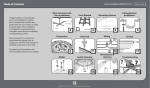
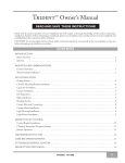
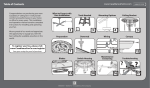
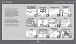
Cottage™ Wet Owner’s Manual
Read and Save These Instructions!
Safety and the proper operation of your Casablanca fan both require a thorough knowledge of the product and proper
installation; therefore, before attempting to install and operate your Casablanca fan, read this owner’s manual completely and
carefully. Retain this manual for future reference.
Caution: To avoid possible electrical shock, make certain that electricity is turned off at the circuit breaker or fuse box
before attempting any installation procedure.
Contents
Introduction............................................................................................................................................................... 2
Before You Start................................................................................................................................................................... 2
Safe Use................................................................................................................................................................................ 2
MOUNTING RECOMMENDATIONS........................................................................................................................... 3
General Guidelines.............................................................................................................................................................. 3
Sloped Ceiling Installations................................................................................................................................................. 3
fan installation......................................................................................................................................................... 4
Fan Preparation.................................................................................................................................................................... 4
Getting Started.................................................................................................................................................................... 5
Ceiling Hardware................................................................................................................................................................. 5
Canopy Gasket Preparation................................................................................................................................................. 5
Crossbar Mounting Bracket Installation.............................................................................................................................. 5
Canopy Installation.............................................................................................................................................................. 6
Hanging the Fan.................................................................................................................................................................. 6
Canopy Electrical Connections............................................................................................................................................ 7
Canopy Hatch Installation................................................................................................................................................... 7
Remove Dummy Switch Housing and Shipping Blocks..................................................................................................... 8
Blade Badge Installation....................................................................................................................................................... 8
Blade Badge and Blade Holder Installation......................................................................................................................... 9
Switch Housing Installation................................................................................................................................................. 9
3-Speed • Operation........................................................................................................................................................... 11
3-Speed • Optional Light Fixture Installation................................................................................................................... 11
Troubleshooting tips.......................................................................................................................................... 12
Care Recommendations...................................................................................................................................... 13
Product Specifications....................................................................................................................................... 13
C12D4301 AT1008
1
Introduction
Before You Start
• CAUTION: RISK OF ELECTRICAL SHOCK! Installation is to be in accordance with the National Electrical Code,
ANSI/NFPA 70-1999, and local codes. All wiring must be performed in accordance with national and local electrical
codes. If you are unfamiliar with the wiring codes, you should use a qualified electrician. To avoid overheating and possible
damage to other equipment, do not install control to a receptacle, fluorescent light fixture, motor operated appliance, or
transformer-supplied appliance.
• This fan is designed to be installed on an existing electrical outlet box. The outlet box must be UL Listed for ceiling fan
installations, if it is not, a new box must be installed. Casablanca extension poles are available for sloped or high ceiling
installations.
• This ceiling fan requires a grounded electrical supply of 120 VAC, 60 Hz and a minimum 15 amp circuit. The maximum
current requirement for the fan with light fixture is 3 amps. The fan uses about 1 amp or 100 watts. Maximum light current
is about 2 amps or 240 watts of lighting.
• Where wire nuts are employed, be sure all bare wires are within the connectors. When installing the canopy hatch, make
sure all wires are within the canopy and that no wires are being pinched.
• WARNING: Do not bend the blade brackets when installing the brackets, balancing the blades or cleaning the fan. Do not
insert foreign objects in between the rotating fan blades.
• WARNING: To reduce the risk of fire or electric shock, do not use this fan with any solid state speed control device. Use
only the control provided with or recommended for this fan.
Unpacking
Before assembling and installing your ceiling fan, remove all parts from the shipping cartons and check them against the parts
listed in the parts guide. Before discarding packaging material, be certain that all parts have been removed.
For best performance and for your warranty to be valid,
use only genuine Casablanca blades, light fixtures, and accessories.
Safe Use
• The blades in each pack are matched for equal weight
to assure smooth fan operation. If more than one fan is
being installed, be careful not to mix blades from different
cartons.
Fuse Box
(Remove fuse for the
circuit you will be
working on)
Circuit Breaker
(Trip breaker for the
circuit you will be
working on)
• Inspect the contents of your carton for possible shipping
or handling damage. If parts are missing or damaged, call
1-888-227-2178.
• It is always a good idea to have an assistant to help with
the installation.
• When cleaning, painting, or working near your fan, be
very careful of the fan and blades. Always turn the power
OFF to the ceiling fan before working on it or replacing
lightbulbs.
• Never insert anything into the path of the fan blades while
the fan is in operation.
• Never install a fan over a pool or spa.
• Never operate a fan that has been damaged in any
way. Contact Casablanca Fan Company by calling
1-888-227-2178, or contact your local authorized
Casablanca dealer for assistance in obtaining service.
2
18”
from tip of
blade to wall
84” from bottom
edge of blade
to floor
Cottage™ Wet
MOUNTING RECOMMENDATIONS
General Guidelines
Before mounting your Casablanca fan, read the following helpful recommendations. The location of the fan, air circulation,
and fan size are all important factors to consider before installation.
Location
Ceiling fans have practical uses in almost every room in your home. We suggest
you follow these mounting recommendations as you decide where to install
your Casablanca fan.
•
•
•
•
For safety reasons, the fan blades must be a minimum of 7’ above the floor.
Do not locate the fan in a doorway or above a swinging door.
In bedrooms, fans work best when mounted above the foot of the bed.
Over pool tables, be sure to provide plenty of clearance to avoid damage from
pool cues.
• Do not install a fan close to or over a pool or spa. High humidity combined
with corrosive gases will destroy the finish and warp the blades.
Fan Size
Variable fan speed capability permits the use of a full-size 52” fan even in smaller rooms. For very large rooms, two fans may
be needed.
Sloped Ceiling Installations
Suggested Extension Pole Lengths
Ceiling Height
8’ 0”
8’ 6”
9’ 0”
9’ 6”
10’ 0”
11’ 0”
12’ 0”
13’ 0”
14’ 0”
Pole Length
Extension
Pole
standard
standard
6”
12”
12”
18”
24”
36”
48”
Maximum
Hang-Tru®
angle 32º
Blades must be a
minimum of 7 feet
above the floor
7’ minimum
When to Use Extension Poles
For optimum performance and appearance, an extension
pole should be used with your Casablanca fan when
installing on high (cathedral) ceilings or sloped ceilings.
Casablanca offers standard poles in increments of 6” up
to 5’. Custom poles are available in lengths up to 9’9”. See
your Authorized Casablanca Dealer for details.
EXAMPLE 1
Note: Fan may wobble or vibrate if pole length is not long
enough and inside blade is too close to downslope or side
wall. Extending pole length will usually solve problem.
EXAMPLE 2
Calculation of Ceiling Angle
Use the tear-off Ceiling Angle Template card inserted in this
manual. It provides you with a simple “go” or “no-go” for
installing your fan on a sloped ceiling.
EXAMPLE 3
This slope is less than 32º.
It is OK to install your fan.
This slope is 32º. This is the maximum
slope that will allow the fan to hang
straight down. It is OK to install your fan.
This slope is more than 32º. Your fan will not
hang straight down, an adaptor is necessary.
Contact your local Authorized Casablanca
Dealer in regards to purchasing a “Sloped
Ceiling Adaptor.”
3
fan installation
Fan Preparation
Perma•Lock™ Hardware (not to scale)
Downrod Gasket
IMPORTANT SAFETY INFORMATION:
Before starting the installation of your ceiling
fan, install the threaded downrod into the motor
coupling and lock the assembly.
Allen Wrench
Perma•Lock™ Downrod
and Ball Assembly
Motor Wires
(leave at least 6” long)
Ground Wire
(green)
Perma•Lock™ Downrod
and Ball Assembly
Prepare for fan installation as follows:
Step 1a. Using the provided Allen wrench (attached to the
paper motor warning shield), loosen the Allen set screw
attached to the motor coupling.
Step 1b. Slide the downrod gasket onto the downrod as
shown, pushing the gasket so that it is snug with the ball
of the downrod.
Downrod Gasket
Allen Wrench
Tapered thread
Motor
Coupling
Allen
Set Screw
Step 1c. Route the wires from the motor housing assembly
through the Perma•Lock™ downrod and ball assembly.
Keep all wires on one side of the pin in the ball. Insert
the downrod into the motor coupling and turn it clockwise
until it stops turning and 2 to 3 threads are still visible.
Tip: The downrod has a tapered thread that is designed
to lock completely when installed correctly.
Step 1d. Tighten the set screw with the Allen wrench to
ensure safe operation of your fan. If it is tight enough, you
should not be able to turn the downrod counterclockwise
with your hands. If in doubt, tighten the set screw with the
Allen wrench until you cannot turn it any further.
Motor Housing
Assembly
Paper Shield
Step 1e. Remove the paper shield from the motor.
Step 1f. Slide the downrod gasket down so that it fits snugly
against the motor casing as shown.
↑
4
↑
CAUTION: Failure to fully lock in the downrod
before securely tightening the Allen set screw may
cause the fan to separate from the downrod and
fall during normal operation.
Cottage™ Wet
Getting Started
Installing a New Ceiling Fixture Outlet Box
If you do not have an existing fixture located where you wish
to place your Casablanca fan, an approved ceiling fixture
outlet box must be installed and wired.
warning!
To reduce the risk of fire, electrical shock, or
personal injury, mount to outlet box marked
“Acceptable Fan Support of 22.7 kg (50 lbs.) or
less” using the mounting hardware provided with
the outlet box.
Using Existing Ceiling Fixture Outlet Box
After turning the power OFF at its source (either the circuit
breaker or fuse box), lower the old fixture and disconnect
the wiring. Check the ceiling fixture outlet box to be sure
it is marked “Approved for Ceiling Fan Mounting.” If it is
not, a new box must be installed.
NOTE: The weight of this fan is 18 pounds.
Ceiling Hardware
Ceiling Hardware (not to scale)
Hanging Plate
Crossbar Mounting Bracket
Canopy Gasket
Wire Nut (4)
Screw Pack A:
2 1/4” x 8-32 Roundhead Screw and Washer (2)
1” x 8-32 Roundhead Screw and Washer (2)
Canopy Gasket Preparation
Step 2. Fit the hanging plate into the canopy gasket as
shown. Make sure that the four holes of the hanging
plate align with the four indentations on the inside of
the gasket.
Canopy
Gasket
Mounting
Bracket
Screw Hole
Hanging
Plate
Crossbar Mounting Bracket Installation
Proceed with installation as follows:
Step 3. Route the wires from the ceiling outlet box through
the center hole of the canopy gasket and hanging plate and
then the crossbar mounting bracket center hole.
Push the mounting hardware included with the outlet
box through the rubber canopy gasket so that the screws
align with the threaded holes of the ceiling fan approved
outlet box.
Using the screwdriver, tighten the screws firmly by hand
only, being careful not to bend the bracket by overtightening.
CAUTION:
To reduce the risk of personal injury, use only the
mounting hardware provided with the approved
outlet box to install the crossbar mounting
bracket.
Ceiling Fan
Approved
Outlet Box
Ceiling Wiring
Canopy
Gasket &
Hanging
Plate
Crossbar
Mounting
Bracket
Ridge
Side
Down
Flat Washer
Green
Ground Wire
Outlet Box
Mounting
Hardware
5
Canopy Installation
Canopy Hardware (not to scale)
Screw Pack B:
Canopy Screws and
Washers (5)
Canopy Hatch
Canopy
Step 4. Attach the canopy to the crossbar mounting bracket
with three of the 8-32 x 21/2” long canopy screws (Screw
Pack B) and lock washers provided with your Casablanca
fan. Tighten using the provided screwdriver until snug
against the ceiling.
Canopy Gasket, Hanging Plate, & Crossbar
Mounting Bracket
Installed
NOTE: On sloped ceilings, align the canopy opening with
the top or peak of the room.
Canopy
Feed outlet box
wires through
canopy opening
Canopy Lock
Washers
Canopy
Screws
Hanging the Fan
Step 5a. To hang the motor housing assembly in the canopy,
hold the motor housing assembly firmly and insert the ball
into the canopy opening. Check that no wires are pinched.
Rotate the motor housing assembly until the slot in the ball
fits into the pin opposite the canopy opening.
Step 5b. Trim excess motor wires, leaving at least 6 inches
above the downrod. Strip 1/2-inch insulation from the end
of each wire using a wire stripper (available at your local
hardware store).
6
Ball
Slot
Pin
Cottage™ Wet
Canopy Electrical Connections
Step 6. Attach the fan wires to the ceiling fixture outlet box
wiring by placing the bare ends of the wires side by side and
then securing with a wire nut. Test that the connection is
secure by pulling on the wire nut. Connect in this order:
• GREEN leads from mounting plate and downrod
assembly of fan to GROUND conductor of power source
(ceiling outlet box). Secure with wire nut.
• WHITE wire from fan to white NEUTRAL wire in
ceiling fixture outlet box. Secure with wire nut.
• BLACK power wire and BLUE wire from fan to black
power wire in ceiling outlet box. Secure with wire
nut.
After making the wire connections, the wires should be
spread apart with the neutral (white) wire and ground
(green) wire on one side of the canopy and the power (black
and blue) wires on the other side.
2 Black Wires
(Power) &
1 Blue Wire
2 White
Wires
(Neutral)
3 Green
Wires
(Ground)
Wire Nut
Note: If the color of your ceiling wires differs from that
described, consult an electrician.
Canopy Hatch Installation
Step 7a. Tuck the wires into the canopy and turn the wires
upward and push them carefully back through the ceiling
plate into the outlet box.
Step 7b. Install the canopy hatch with the canopy screw and
lock washer (Screw Pack B) using the provided screwdriver.
To do this, tilt the motor housing assembly away from the
hatch opening. Tighten the screws firmly.
Step 7c. Straighten the fan, then check to ensure there is
no movement between the canopy and the ceiling or the
Perma•Lock™ downrod and the ball assembly.
7
Remove Dummy Switch Housing and Shipping Blocks
Step 8. To reach the blade holder mounting holes in the fan
motor, the dummy switch housing must be removed.
Take out the two 5/32-32 x 3/8” screws securing the
dummy switch housing as shown. Put the two screws aside
for the moment. They will be used in Step 13a to install the
switch housing after the blades are installed. The dummy
switch housing is used only when shipping the fan.
TIP: Rotate the motor beneath the switch housing plate
to access the shipping block screws through the hole in the
switch housing plate.
Dummy Switch
Housing
Step 9. Unscrew and remove the five shipping blocks.
Retain the five screws for use in Step 11b to install the
blade/blade holder assembly. You can discard the shipping
blocks. The shipping blocks are only used when shipping
the fan.
IMPORTANT!
Retain the five screws removed in Step 9 for use
in Step 11b.
Hole in Switch
Housing Plate
Shipping
Block
Blade Badge Installation
Blade Hardware (not to scale)
Blade Badge (5)
Blade Holder (5)
Medallion Nails (20)
Screw Pack C:
Blade Badge Screws (21)
Screw Pack D:
Blade Holder Screws (6)
Attach Blade Holders
Step 10. Using Screw Pack C and the provided screwdriver,
carefully align the Medallion Nail on the front of the blade
badge and install the screw. NOTE: The front of the blade
badge is the side with the beadboard. Tighten securely by
hand. Repeat three more times per blade badge. And repeat
for each blade badge. (Check installation to make sure that
the Medallion Nails are aligned straight.)
warning!
Do not use electric screwdriver to tighten blade
screws. Hand tighten using a manual screwdriver
only.
8
Front of Blade
Cottage™ Wet
Blade Badge and Blade Holder Installation
Step 11a. Carefully tilt the blade holder between the switch
housing motor plate and the motor, as shown.
TIP: Rotate the motor beneath the switch housing plate
to attach the blade/blade holder assembly.
Step 11b. Using the screws from Screw Pack D, the screws
removed in Step 9, and the screwdriver provided, attach
the blade/blade holder assembly to the motor. Tighten
securely by hand only.
Step 11c. After all blade holders are installed, install the
gasket into the switch housing mounting plate. The smooth
side of the gasket should face the fan motor.
Caution:
Handle the gasket carefully to avoid tearing.
Switch Housing Gasket
TIP: For balancing purposes, loosely install all five blades
to the motor before tightening the blade screws securely.
Caution:
Blade screws must be tightened securely before
operating the fan.
Switch Housing Installation
Preparation
Step 12. Locate the switch housing cap assembly and
remove the two 8-32 x 3/8” screws holding the cap onto
the switch housing. Remove the cap and gasket.
NOTE: Save the two screws — they will be used in Step
15.
9
Switch Housing Installation (CONTINUED)
Install the Switch Housing Mounting Screws
Step 13a. Locate the two dummy switch housing screws
you removed in Step 8. Install them onto the motor as
shown, leaving approximately 1/8” of the threads exposed
for installation of the switch housing.
IMPORTANT:
If you are installing an optional light fixture at this
time, proceed to Step 6 of OPTIONAL LIGHT
FIXTURE INSTALLATION on page 11 now.
↑
Step 13b. Connect the plug connector from the motor to
the plug connector from the switch housing assembly.
CAUTION:
Both plug connectors are polarized and will only
fit together one way. Make sure the connectors are
properly aligned before connecting them. Incorrect
connections could cause improper operation and
damage to the product.
Step 13c. Line up the two keyholes in the switch housing
cup with the two screws installed in Step 13a.
Step 13d. Rotate the cup so that the screws are aligned
with the smaller side of the keyholes. Tighten the screws
securely by hand only.
Install the Switch Housing Cap
NOTE: Before re-installing the cap, the gasket must be
put on the cap so that the larger gasket holes go over the
alignment pins.
Step 14. Line up the two guide pins in the cap with the
two alignment holes of the switch housing. NOTE: The
alignment holes are the larger, non-threaded holes in the
raised rim of the switch housing. Press the cap onto the
switch housing to seat the guide pins into the alignment
holes of the switch housing.
Step 15. Re-install the two screws removed in Step 12 to
tighten the switch housing cap and switch housing.
Step 16. Attach a fandangle to each of the pull chains using
the breakaway connectors.
10
↑
Guide Pin
Cottage™ Wet
3-Speed • Operation
Pull-chain switches on the fan control the fan and blade
rotation.
Using the fan control pull-chain switch:
Fan off at start.
• First pull: fan ON, low speed
• Second pull: medium speed
• Third pull: high speed
• Fourth pull: fan OFF
Using the blade rotation (reversing) pull-chain switch:
Blade rotation controls the airflow direction. Each pull of
the pull-chain switch toggles the blade rotation.
NOTE: Ceiling fans work best by blowing air downward
(counterclockwise blade rotation) in warm weather to cool
the room with a direct breeze. In cold weather, having
the fan draw air upward (clockwise blade rotation) will
distribute the warmer air trapped at the ceiling around the
room without causing a draft.
3-Speed • Optional Light Fixture Installation
If you are installing a light kit to an existing fan, follow all
instructions below.
11.Connect the WHITE wire from the switch housing to
the WHITE wire from the light kit. Secure the splice
with a wire nut.
1. Remove the switch housing cap by loosening the two
8-32 screws that attach it to the switch housing.
NOTE: If a separate circuit is used to control the lights
from a wall control, the BLUE D1-Option wire in the
canopy should be connected to that switch leg with the
BLACK fan power wire.
If you are installing the light kit with the fan, skip
Steps 1-5.
2.Loosen the screws securing the switch housing to the
motor. NOTE: You do not need to remove these screws,
just loosen them enough to turn the housing.
3. Rotate the switch housing so that the screws are aligned
with the larger side of the keyholes.
4. Pull the switch housing away f rom the motor
assembly.
5.Disconnect the switch housing plug connector from the
motor plug connector by pressing down on the handle
of the small clasp and pulling apart.
Return to Steps 13b-15 (SWITCH HOUSING
INSTALLATION) to attach (or re-attach) the switch
housing to the motor assembly. Refer to your light kit
instructions to assemble and attach the rest of your light
kit correctly.
WHITE
6. Remove the plug from the switch housing.
7.Install the pull-chain switch as follows:
• Remove the collar from the switch
• Thread the pull chain through the hole in the switch
housing
BLUE
Light
Pull-Chain
Switch
BLACK/BLUE
• Place the switch so that the neck protrudes from
the hole
Collar
• Thread the collar back over the chain and handtighten the collar on the neck of the switch
8. Thread the two wires from the light kit through the
hole in the center of the switch housing.
Switch Housing Plug
9. Connect one wire from the pull-chain switch to the
BLUE D1-Option wire. Secure the splice with a wire
nut.
10.Connect the other wire from the pull-chain switch to
the BLACK wire from the light kit. Secure the splice
with a wire nut.
Light Fixture
11
Troubleshooting tips
Please refer to this troubleshooting guide before requesting service or contacting your dealer for assistance.
PROBLEMPOSSIBLE REMEDIES
Fan will not start
Fan wobbles or shakes excessively
• Check the main circuit fuses, circuit breakers, and wall switch position. Check all
wire connections. Make sure the power is turned off during this inspection.
• Check that reverse switch is not set in center of throw.
• Be sure the canopy pin is set properly into the slot on the ball.
• Check that the bladeholders have not been bent during installation and the blades
are balanced.
• Screws for bladeholders to motor are tight.
• The hanger bracket and/or the ceiling outlet are attached too loosely. Make sure
the hanger bracket is attached tightly to the ceiling outlet box and the downrod
assembly is secured firmly.
• The downrod is attached to the downrod base too loosely. Make sure all the screws
are securely tightened.
Fan is noisy during operation
• Screws for blades are tight.
• Check and tighten the light fixture retaining screws, glass shade screws, and/or
lightbulb(s).
• Tighten the canopy screws and mounting plate assembly. Make sure the wire nuts
inside the canopy and switch housing are not touching the metal parts and that
they have not fallen off the wire splices. Tighten as necessary.
• Tighten the blade holders to the flywheel (or direct drive motor) and the blade to
the bladeholder screws.
Fan does not run on low speed
Light works, but fan does not work
Fan works, but light does not work
Fan will not operate at proper speeds
or
will not operate at any speed
• Make sure all the screws in the motor housing are snug but not overly tight.
• If fan is new, it may need to be “broken in.” Run at high speed for several days.
• The fan wires are not connected properly. Follow the instructions in Step 7.
• The light socket is broken. Replace the socket.
• A lightbulb is defective. Replace the lightbulb.
• Defective three-speed pull-chain switch assembly
• Defective capacitor; replace three-speed pull chain switch assembly or replace PCB
assembly
Fan runs slowly in either direction if
• Defective reverse switch
rotation
is
started
by
hand;
will
not
reverse
• Defective capacitor
• Open motor winding: replace reverse switch assembly, PCB assembly, or motor
unit
12
Cottage™ Wet
Care Recommendations
Fan Finishes
• For cleaning, a soft brush or lint-free cloth should be used to prevent scratching the finish.
• A vacuum cleaner brush nozzle can remove heavier dust.
• Surface smudges or an accumulation of dirt and dust can be removed easily using a mild detergent and slightly dampened
soft cloth. An antistatic agent may be used, but never use abrasive cleaning agents as these will damage the finish.
Blades
• Wood-finish blades should be cleaned with a furniture polishing cloth. Occasionally, a light coat of furniture polish may be
applied for added protection and beauty.
• For painted, high-gloss or plastic blades (ABS), surface smudges or an accumulation of dirt and dust can be removed easily
using a mild detergent and slightly dampened soft cloth. An antistatic agent may be used, but never use abrasive cleaning
agents as these will damage the finish.
No Need for Lubrication
• Never lubricate this fan! The precision motor at the heart of your Casablanca fan features sealed bearings that are lubricated
for life.
• Do not attempt to oil the motor.
Changing Lightbulbs
• Be sure to turn the power to OFF at the wall switch or circuit breaker before changing lightbulbs.
• Replace bulbs with the same type as you removed from the light fixture.
• The maximum wattage rating for this fan’s light kit is 240 watts.
For questions or to locate the nearest Casablanca Authorized Service Center call toll free: 1-888-227-2178
or visit us on the Web at: www.casablancafanco.com
Product Specifications
Model Name:
Model Number:
Cottage™ Wet
C12DXXD
Weight:
18 lbs.
Dimensions:
Dimension B
NOTE:
includes light fixture
and glass.
A = 12”
B = 13”
C= 3”
D= 13.3”
E = 5.6”
Motor:
188 x 20mm Direct DriveTM
Blade Span:
52”
Blade Iron Pitch: 15°
No. of Blades:
5
Technology:
3-Speed
Airflow:
6,361 cfm
Electricity Use*:
85 watts
Airflow Efficiency*:
77.3 cfm/watt
* Performance data is for fan only. No lighting wattage is included.
13