1
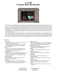
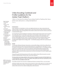
SYSTXCC4ZC01
Infinity Damper Control
Visit www.carrier.com
Installation and Start-Up Instructions
GER, WARNING, and CAUTION. These words are used with
the safety-alert symbol. DANGER identifies the most serious
hazards, which will result in severe personal injury or death.
WARNING signifies a hazard, which could result in personal
injury or death. CAUTION is used to identify unsafe practices,
which would result in minor personal injury or product and
property damage. NOTE is used to highlight suggestions which
will result in enhanced installation, reliability, or operation.
INSTALLATION CONSIDERATIONS
Before the actual installation of a zoning system can begin,
decisions need to be made to determine the number and location of
zones and sensors. This affects duct and damper selections.
Infinity Damper Control
SYSTXCC4ZC01
A97040
NOTE: Read the entire instruction manual before starting the
installation.
This symbol → indicates a change since the last issue.
TABLE OF CONTENTS
SAFETY CONSIDERATIONS .....................................................1
INSTALLATION CONSIDERATIONS .......................................1
INTRODUCTION ..........................................................................1
INSTALLATION ...........................................................................2
Check Equipment and Job Site...........................................2
Component Location and Wiring Considerations ..............2
Install Components ..............................................................3
Install Zone Dampers ..........................................................3
Final Wiring.........................................................................4
Additional Damper Control Board Setup ...........................5
Optional Transformer Requirements...................................5
System Startup.....................................................................5
TROUBLESHOOTING .................................................................7
SAFETY CONSIDERATIONS
Improper installation, adjustment, alteration, service, maintenance,
or use can cause fire, electrical shock, or other conditions that may
cause personal injury or property damage. Consult a qualified
installer, service agency, or your distributor or branch for information or assistance. The qualified installer or agency must use
factory authorized kits or accessories when modifying this product.
Refer to the individual instructions packaged with the kits or
accessories when installing. Follow all safety codes and wear
safety glasses. Have fire extinguisher available. Read these instructions thoroughly and follow all warnings or cautions attached
to the unit. Consult local and state building codes and Sheet Metal
and Air Conditioning National Association (SMACNA) for special
installation requirements.
This is the safety-alert symbol
. When you see this symbol on
the equipment and in the instruction manual, be alert to the
potential for personal injury. Understand the signal words DAN-
This instruction covers the physical installation and start up of the
Infinity Damper Control. Use this instruction to guide the actual
installation process after all the air side decisions have been made.
One Damper Control is capable of handling up to four zones of
operation. When greater than four zones are required, a second
Damper Control Module is needed for zones 5 through 8 (8 zones
maximum).
1. Install the Infinity Zone Control (User Interface) and Remote
Room Sensors in non-condensing areas with ambient temperatures between 32° F. and 120° F. Install Dampers and Infinity
Damper Control in non-condensing areas with ambient temperatures between -4° F. to 158° F., (-20° to 70° C).
2. A TXV is required on the indoor coil when used with all
residential split system equipment.
3. Proper equipment selection and duct sizing are important in a
zoned system.
4. DO NOT USE a bypass damper with the Infinity Zoning
System. Addition of a bypass will cause improper operation.
Airflow management will be performed by the User Interface
algorithms. The User Interface will monitor the system and
will maintain proper airflow through the heating / cooling
equipment.
INTRODUCTION
The Infinity Zoning System allows air conditioning and heating
equipment to control temperatures and humidity in up to 8 distinct
spaces, or zones, within a building. Each zone has independent
temperature settings. The comfort temperature settings can change
automatically through the use of schedules. This allows the Infinity
System to change temperature settings in zones to reflect occupancy or usage. For example, the end user can condition bedrooms
in a home from 5:00 PM through 7:00 AM or the kitchen from
3:00 PM through 6:00 PM. The Infinity System uses motorized air
volume control dampers (also called zone dampers) to regulate
flow of conditioned air into zones. In this manner, the system can
selectively heat or cool certain portions of a building depending
upon space temperature requirements.
Each zone requires a motorized zone damper to control the air
supplied to it and a zone sensor to sense temperature in each zone.
There are three types of zone sensors available and may be used in
combination:
Manufacturer reserves the right to discontinue, or change at any time, specifications or designs without notice and without incurring obligations.
Book 1 4
PC 101
Catalog No. 809-50012
Printed in U.S.A.
Form DAMP4ZC-1SI
Pg 1
04-04
Replaces: NEW
Tab misc. misc.
•
Zoning User Interface (p/n SYSTXCCUIZ01) — Each installation has only 1 User Interface. This is the command center for
the entire system. It will typically be located in Zone 1 to sense
and control the temperature in this zone. If desired, a Remote
Room Sensor or a Smart Sensor may be used to sense the Zone
1 temperature. This can give the installer some flexibility in
locating the User Interface to another area.
• Remote Room Sensor (p/n SYSTXCCRRS01) — Any zone
may use a Remote Room Sensor (including Zone 1). This is a
temperature sensor only, having no additional user inputs. In
applications where zone temperature averaging may be desired,
this may be done using 4 Remote Room Sensors in a series /
parallel wiring configuration (See Fig. 11 for Remote Room
Sensor Averaging).
• Smart Sensor (p/n SYSTXCCSMS01) — Any zone may use a
Smart Sensor (including Zone 1). It provides a temperature
display and buttons to adjust the desired temperature in that
zone only. It also displays the outdoor temperature and indoor
humidity.
LOCATING ZONING USER INTERFACE — The User Interface is the command center for the Infinity Zone System. It should
be located where it is easily accessible and visible to home or
business owner. It is also normally the Zone 1 sensor and as such
needs to be located to properly measure the temperature in Zone 1.
If these two requirements conflict, a separate Remote Room
Sensor can be added for Zone 1.
Be sure to select the desired sensor type for each zone. Zone
sensors other than the User Interface must be purchased separately.
Installation Instructions for these sensors are included with them.
LOCATING SENSORS — For proper operation, each sensor
must accurately measure the temperature within its zone. For
accurate temperature measurement, the following guidelines
should be followed:
When a Remote Room Sensor is connected to Zone 1 terminals(ZS1 and ZS1C) of the Infinity Damper Control, the system
automatically switches to using this sensor for Zone 1 and ignores
the sensor within the User Interface. This arrangement allows the
User Interface to be located at any convenient place within the
home or business. In this arrangement, only the Zone 1 Remote
Room Sensor must be located in Zone 1.
NOTE: The User Interface also controls humidity functions. If
the User Interface is not used to control Zone 1 temperature, it
must still be located in a suitable area where humidity control will
not be affected.
INSTALLATION
Step 1—Check Equipment and Job Site
Sensor should be mounted:
• Approximately 5 ft. (1.5m) from floor.
• Close to the center of its zone, preferably on an inside wall.
• On a section of wall without pipes or ductwork.
Sensor should NOT be mounted:
INSPECT EQUIPMENT — File claim with shipping company,
prior to installation, if shipment is damaged or incomplete.
Step 2—Component Location and Wiring Considerations
• Close to a window, on an outside wall, or next to a door leading
to the outside.
• Where it will be exposed to direct light and heat from a lamp,
sun, fireplace, or other temperature radiating object which may
cause a false reading.
• Close to or in direct airflow from supply registers.
• In areas with poor air circulation, such as behind a door or in
an alcove.
WIRING CONSIDERATIONS — Ordinary thermostat wire is
ideal when wiring the Infinity Zoning System (shielded cable is
not necessary). Use 22 AWG or larger for typical installations.
Lengths over 100 ft. should use 20 AWG or larger wire. Remote
Room Sensors require only 2 conductors, but it is recommended
that at least 4 conductors be run. This will allow a Smart Sensor to
replace the Remote Room Sensor with no wiring changes at a later
date. The User Interface requires 4 conductors, each damper
actuator requires 3 conductors. Cut off or fold back and tape any
unneeded wires. Plan the routing of wiring early to avoid possible
problems later. Remember, all wires converge at the Infinity
Damper Control, so its location is important.
ELECTRICAL SHOCK HAZARD
Failure to follow this warning could result in personal injury
or possible equipment damage.
Disconnect supply power before routing wire.
NOTE: All wiring must comply with national, local, and state
codes.
LOCATING INFINITY DAMPER CONTROL
— All system wiring is run back to the Infinity Damper Control.
Select a location near the Infinity furnace or fan coil where wiring
from the User Interface, each Remote Room Sensor or Smart
Sensor, each damper actuator, and the equipment itself can come
together easily.
The Infinity Damper Control is approved for indoor use only and
should never be installed with any of its components exposed to
the elements. The Infinity Damper Control (and the zone dampers)
may be installed in any area where the temperature remains
between -4° F. to 158° F. (-20° C to 70° C), and where there is no
condensation. The cover must be installed to prevent damage from
other sources. Do not locate where it will be accessible to children.
It may be mounted in either vertical or horizontal position.
Remember that wiring access is likely the most important consideration.
NOTE: Wiring of the ABCD bus only requires a four wire
connection; however, it is good practice to run thermostat cable
having more than four wires in the event of a damaged or broken
wire during installation.
The following color code is recommended for each ABCD bus
connection:
A — Green = Data A
B — Yellow = Data B
C — White = 24 VAC (Com)
D — Red = 24VAC (Hot)
ELECTRICAL OPERATION HAZARD
Failure to follow this caution will result in equipment damage
or improper operation.
To prevent possible damage to the Infinity Damper Control,
do not mount on plenum, duct work, or flush against furnace.
It is not mandatory that the above color code be used, but each bus
connection in the system MUST be wired consistently.
2
Step 3— Install Components
INSTALL INFINITY DAMPER CONTROL — The Infinity
Damper Control is designed so that wires can enter it from behind,
above, or below. Plan wire routing before mounting Damper
Control.
1. Remove cover to access mounting holes.
2. Mount back plate to wall using screws and wall anchors
provided.
3. Level back plate and tighten screws.
INSTALL ZONING USER INTERFACE — (see Infinity Zone
Control Installation Instructions for details).
NOTE: Improper wiring of the ABCD connector will cause the
Infinity Zoning System to operate improperly. Check to make sure
all wiring is correct before proceeding with installation or turning
on power.
INSTALL REMOTE ROOM SENSORS —
1. Separate the sensor cover and mounting back plate by squeezing the top and bottom of the cover together firmly by
grasping the raised top and bottom ridges. This will release the
cover. Mount to wall using provided screws and anchors.
2. Pull a 2-conductor wire through hole on right-hand side.
3. Recommended connection is BLACK to either terminal,
WHITE to remaining terminal (sensor terminals are not
marked for polarity because polarity is not important).
Stranded or common bell wire may be used. Lengths up to
1000 ft. will contribute no noticeable error.
4. Push any extra wire into wall and seal hole to prevent air
leaks. Align sensor cover with base plate then press firmly
until cover snaps into place.
INSTALL ZONING SMART SENSOR — See Infinity Zoning
Smart Sensor Installation Instructions for details.
Step 4— INSTALL ZONE DAMPERS
Proper selection and sizing of dampers is very important for proper
system operation. Be sure to consult the Damper Product Data
Digest for assistance in making these selections. Selection and
sizing information is not provided in this installation instruction.
Zone dampers are available in round, rectangular, and slip-in
design and may be installed in any position. Install dampers so that
actuator is visible for inspection and accessible in the event it
would need to be serviced. The black mark on the end of the
damper shaft represents position of damper blade. To wire damper,
locate terminals labeled: OPN (open); COM (common); CLS
(closed; and wire appropriately (see Fig. 1 for Damper 24 VAC
connection).
If duct system requires multiple dampers for a single zone, up to
5 dampers (maximum) may be wired in parallel. For all applications, including retrofit, it is recommended to use only current
dampers with direct-drive style actuators. DO NOT use older
damper with crank-arm style actuators.
If an actuator is removed from a damper for any reason, it must be
properly aligned when it is reinstalled. This can be done by
rotating the actuator and the blade to their closed positions and
then tightening the actuator (set screw) to the shaft. This assures
alignment at the closed position. (Pressing the quick blade release
button allows the actuator to be manually turned).
ELECTRICAL OPERATION HAZARD
Failure to follow this caution will result in euipment damage
or improper operation.
Condensation can damage the actuator. When dampers are
located in an unconditioned space, condensation is likely to
occur in cooling. To prevent condensation and losses, all
dampers and ductwork in unconditioned space must be
insulated or otherwise protected.
Whenever condensation might occur, it is recommended that a
plastic actuator cover (p/n, DAMPACTXXCOV) be used over the
actuator. These covers can help prevent condensation on actuators
by locking out ambient humidity. Insulation may be applied over
the cover to minimize heat transfer.
To install, place the cover over actuator and seal in place over the
surrounding insulation with duct tape on all four sides. Sealing
need not be perfect because there will be positive pressure inside
the cover. Do not mount the dampers with their actuators hanging
directly beneath the ductwork. It is best to mount the actuator
facing in either the three or nine o’clock position.
For specific duct types, follow instructions below:
NOTE: All zone dampers and ductwork must be properly supported according to local codes or SMACNA standards.
ROUND METAL DUCTWORK
1. Crimp end of branch duct.
2. Slip end of zone damper over end of ductwork. Use selftapping sheet metal screw to secure.
3. Properly seal joint using duct tape, mastic, or other approved
method. Do not allow mastic to come in contact with actuator.
4. If dampers are applied in an unconditioned space, insulate
damper using 1-1/2 inch to 2 inch insulation (See Fig. 2).
RECTANGULAR DUCTWORK
1. Make connections using S-lock and drives (See Fig. 3).
2. Properly seal joint using duct tape, mastic, or other approved
method. Do not allow mastic to come in contact with actuator.
3. If dampers are applied in an unconditioned space, insulate
damper using 1-1/2 inch to 2 inch insulation (See Fig. 4).
ROUND FLEXIBLE DUCTWORK
1. Slip one end of flexible ductwork over end of zone damper
(See Fig. 5).
2. Secure flexible duct to zone damper using SMACNA or other
approved method.
3. Properly seal joint using duct tape, mastic, or other approved
method. Do not allow mastic to come in contact with actuator.
4. If dampers are applied in an unconditioned space, insulate
damper using 1-1/2 inch to 2 inch insulation (See Fig. 6).
RECTANGULAR FIBROUS GLASS DUCTWORK
1. Insert one end of zone damper into end of fibrous glass
ductwork approximately 2 to 3 inches (See Fig. 7).
2. Use field supplied screws to secure duct board to zone
damper.
3. Properly seal joint using duct tape, mastic, or other approved
method. Do not allow mastic to come in contact with actuator.
4. If dampers are applied in an unconditioned space, insulate
damper using 1-1/2 inch to 2 inch insulation (See Fig. 8).
3
SET SCREW
SET SCREW
MOUNTING HUB
FLEXIBLE
DUCT
3/16"
GAP
ZONE
DAMPER
MOUNTING HUB
DAMPER
ACTUATOR
HOUSING
PLASTIC COVER
QUICK BLADE
RELEASE
CLS COM OPN
CLS COM
3/16"
GAP
ANTI-ROTATION
MOUNTING SCREW
Fig. 5 — Round Flexible Duct Work
A95132
OPN
1/ 2 ″
(CLS) CLOSED
(COM) COMMON
(OPN) OPEN
STEEL STRAP
ANTI-ROTATION
MOUNTING SCREW (5/16")
Fig. 1 — Damper 24-vac Connections
C03024
1
/ 2 ″ STEEL STRAP
Fig. 6 — Insulated Round Flexible Duct Work
A95133
FIBROUS
GLASS
DUCTWORK
FIELD
SUPPLIED
SCREWS
ZONE
DAMPER
Fig. 2 — Insulated Round Metal Duct Work
A95130
2″ TO 3″
Fig. 7 — Rectangular Fibrous Glass Duct Work
S-LOCK
A92480
SUPPLY
AIR DUCT
DRIVE
1 1/ 2 ″ TO 2″
INSULATION
ZONE
DAMPER
Fig. 8 — Insulated Rectangular Fibrous Glass Duct
Work
Fig. 3 — Rectangular Metal Duct Work
A95134
A92478
are in parallel with each other. Use either terminal block to connect
the Zoning User Interface, Smart Sensor(s), variable-speed indoor
unit and 2-speed communicating outdoor unit (if applied). If more
than four zones are required (up to 8 zones maximum), see
Step—6 and Fig. 10 for Additional Damper Control Board Setup
for Zones 5-8.
1 1/2 " TO 2"
INSULATION
VENTILATOR WIRING — The Infinity Damper Control can
control a Carrier Heat Recovery Ventilator or Energy Recovery
Ventilator (HRV / ERV). Connect the four wires from the
ventilator control board (see ventilator installation instructions for
details) to the connector labeled (YRGB). This label identifies the
color of the wire to match the ventilator wire colors (Y=yellow,
R=red, G=green, B=blue or black). If you have two Infinity
Damper Controls, connect the ventilator to the control for zones 1
through 4.
Fig. 4 — Insulated Rectangular Metal Duct Work
A95131
Step 5—FINAL WIRING
Bring all damper and sensor wires together at the Infinity Damper
Control. Make all system wiring connections as indicated in Fig. 9.
The two ABCD bus connections on the Infinity Damper Control
LEAVING AIR TEMPERATURE / HEAT PUMP TEMPERATURE (LAT/HPT) SENSORS — These inputs on the
Infinity Damper Control are used only for diagnostic purposes and
4
NOT required for regular use. Traditionally, the LAT/HPT sensors
were required for temperature / equipment monitoring. The Infinity Zoning System does not require these because the User
Interface algorithms will perform temperature and airflow management without use of these sensors. If desired, one or both
sensors may be used in monitoring leaving air temperature and / or
indoor coil air temperature. Consideration and / or flexibility will
now permit using one of these sensors in the return air duct giving
the dealer an option to view both entering and leaving air
temperature at the User Interface. If applied, connect sensors to the
LAT / HPT terminals (See Fig. 9, System Wiring, for connection
to Infinity Damper Control). LAT is monitored by both AC and HP
systems. LAT and HPT are both monitored only in HP systems.
FUSE — A 1-amp automotive type fuse is used to protect the
Infinity Damper Control from over current on the damper drive
outputs. If this fuse fails, damper wiring should be inspected for
shorts. Also, no more than five damper motors should be connected to a single damper output. Fuse should always be replaced
with an identical 3 amp automotive fuse.
Step 6—ADDITIONAL DAMPER CONTROL BOARD
SETUP
If you have more than four zones, a second Infinity Damper
Control must be used and both dip switch settings on the second
board supporting zones 5 through 8 must be moved to the right.
The ABCD bus connector must be wired between both Infinity
Damper Controls.
To install - Locate LAT sensor in main supply trunk after heating
and cooling coil and before first branch. The LAT sensor is radiant
shielded to prevent heat from affecting correct air temperature.
Step 7—Transformer Requirements
The Infinity Zoning System has a lower power draw from the
system transformer than previous controls. It also drives only 2
zone damper outputs at a time. As a result, up to 8 zones each with
up to 5 dampers, plus a smart sensor, can be handled without
increasing the size of the system transformer or adding a second
zoning transformer.
1. Drill a 1/4 inch hole at location in supply trunk where sensor
will be installed.
2. Insert sensor in hole and use as a template to mark the 2
mounting holes.
3. Drill two 1/16 inch holes to accept No. 6 screws through
pre-drilled holes in duct temperature sensor back plate.
Use of the transformer provided in the furnace or fan coil is
recommended without change in all zoning applications except
those having a System Access Module (SAM). The SAM requires
a separate transformer.
4. Use two No. 6 sheet metal screws to mount duct temperature
sensor to unit.
5. Connect sensor to 2-conductor wire using provided wire nuts.
For those who still want more transformer capacity, a 60 VA
system transformer may be used in place of the supplied 40 VA
part.
The HPT sensor (in heat pump applications) measures the temperature of the air leaving the indoor coil. The sensor is installed
downstream of the indoor coil but before the electric heaters. It can
be installed through the wall of the fan coil or may be located
entirely inside the fan coil near the blower inlet. Anchor firmly in
place with cable ties so that it cannot interfere with the blower
wheel (See Fig. 9).
Step 8—System Start-Up
Follow the system start-up process outlined in the Infinity Zone
Control Installation Instructions for details.
LED INDICATORS — Under normal operation, the Yellow and
Green LEDs will be on continuously (solid). If the Infinity Damper
Control does not receive communications with the User Interface,
the Green LED will not be on. If there are faults present, the
Yellow LED indicator will blink a two-digit status code. The first
digit will blink at a fast rate, the second at a slow rate.
STATUS CODE
16 =
24 =
45 =
46 =
DESCRIPTION
Communication Failure
Damper Fuse Failed
Board Failure
Low Input Voltage
5
ABCD Connection:
A = Green: RS485+
B = Yellow: RS485C = White: 24VAC (COM)
D = Red:
24VAC (HOT)
Zoning User Interface &
Smart Sensor(s)
Connection
2-spd.
Outdoor
Unit
ABCD
Ventilator
Unit
YRGB
ABCD
ABCD
Zone-1
Damper
CLS1
COM1
OPN1
Zone-2
Damper
CLS2
COM2
OPN2
Zone-3
Damper
CLS3
COM3
OPN3
Optional Leaving Air & Heat Pump
Temperature Sensor
Indoor
Unit
ABCD
YRGB
ABCD
See Note _
LAT COM HPT
FUSE
ZS1
ZS1C
Optional
Zone-1
Sensor _
ZS2
ZS2C
Zone-2
Sensor
ZS3
ZS3C
Zone-3
Sensor
ZS4
ZS4C
Zone-4
Sensor
DIP Switch
ON
Status LEDs
Yellow
Zone-4
Damper
1 2
Dampers:
CLS_ = Close
COM_ = Common
OPN_ = Open
OFF
CLS4
COM4
OPN4
Green
Damper Control Module, Zones 1 - 4
Notes:
_ ABCD CONNECTORS ARE IN PARALLEL WITH EACH OTHER. USE EITHER TERMINAL BLOCK FOR ANY ABCD CONNECTION.
_ INSTALLING ZONE-1 REMOTE ROOM SENSOR WILL OVERRIDE USER INTERFACE TEMPERATURE SENSOR.
Zoning System Wiring Diagram
Zones 1 - 4
Fig. 9 — System Wiring
A03161
Connect to Zones 1-4
Damper Control
Module
For Zones 5-8, a second Damper
Control Module must be applied
ABCD
No Connection
ABCD
Zone-5
Damper
CLS1
COM1
OPN1
Zone-6
Damper
CLS2
COM2
OPN2
Zone-7
Damper
CLS3
COM3
OPN3
Zone-8
Damper
CLS4
COM4
OPN4
YRGB
ABCD
See Note _
LAT COM HPT
FUSE
ZS1
ZS1C
Zone-5
Sensor
ZS2
ZS2C
Zone-6
Sensor
ZS3
ZS3C
Zone-7
Sensor
ZS4
ZS4C
Zone-8
Sensor
DIP Switch
ON
1 2
Dampers:
CLS_ = Close
COM_ = Common
OPN_ = Open
ON
ON = Zones 5-8
Yellow
Green
Damper Control Module, Zones 5 - 8
Notes:
_ FOR ZONES 5 THROUGH 8: A SECOND DAMPER CONTROL MODULE IS REQUIRED. BUS CONNECTION
ABCD MUST BE CONNECTED BETWEEN BOTH DAMPER CONTROL MODULES.
_ SET BOTH DIP SWITCH POSITIONS TO ON (right position) AT SECOND MODULE ONLY TO ACTIVATE ZONES 5-8.
Zoning System Wiring Diagram
Zones 5 - 8
Fig. 10 — Additional Damper Control
Board Setup for Zones 5 - 8
A03162
6
Damper Control
Module
ZS_
Damper Control
Module
ZS_C
Sensor 1
Sensor 2
Sensor 3
Sensor 4
Fig. 11 — Remote Room Sensor Averaging
4-Sensor Application (series- parallel)
A03233
Zoning User Interface Display says, ″Outdoor Unit Not
Found″, when applied with a two-speed communicating outdoor unit:
1. Recheck wiring to ABCD connector on outdoor unit. Make
sure all colors match for every terminal.
Zoning User Interface cannot find Zones 5 through 8:
1. Make sure zone module 5 - 8 has the dip switches set to the far
right.
2. Recheck wiring to the ABCD connections.
Zoning User Interface can find zones 5 - 8 but not 1 - 4:
1. Make sure zone module 1 - 4 has the dip switches set to the far
left.
2. Recheck wiring to the ABCD connections.
Some zones do not provide enough comfort (a noticeable
difference exists between the actual room temperature and
operating set point or equipment does not turn on)
1. The zone airflow limit may be set too low. Perform the zone
airflow limit checkout procedure. See Infinity Zoning System
User Interface installation instructions for details.
Some zones provide too much airflow and are noisy:
1. The zone airflow limit may be set too high. Perform the zone
airflow limit checkout procedure. See Infinity Zoning System
User Interface installation instructions for details.
Zone dampers do not move:
1. Check fuse located on Infinity Damper Control. If fuse failed,
check damper wiring and inspect for shorts. No more than five
damper motors should be connected to a single damper output.
Fuse should be replaced with an identical 3 amp automotive
fuse.
TROUBLESHOOTING
Zoning User Interface Control does not power up:
1. Recheck wiring to ABCD on all devices. Make sure all colors
match for every terminal.
2. Make sure power is applied to the indoor unit, and the Yellow
and Green LEDs are lit on the Infinity Damper Control.
3. Check for 24 VAC between the C and D terminals at the User
Interface terminal block.
4. Check fuse at indoor unit circuit board and Infinity Damper
Control.
Zoning User Interface Display says, ″Indoor Unit Not Found″:
1. Recheck wiring to ABCD on all devices. Make sure all colors
match for every terminal.
2. Press side button at User interface to try again.
3. Check power to indoor unit.
4. Disconnect all ABCD connections from every device and only
reconnect the User Interface to the indoor unit. If the indoor
unit is identified by the User Interface, then another device on
the ABCD connection may be at fault. Reconnect each
device’s ABCD connection one at a time and perform a
Re-Install from the Service Menu after each connection is
made. If one or more devices are not found after reconnecting
the last device, the last device may be suspect.
5. If the ABCD connection only contains an indoor unit and a
User Interface, then the wiring, indoor unit control board, or
User Interface may be at fault.
7
Copyright 2004 CARRIER Corp. • 7310 W. Morris St. • Indianapolis, IN 46231
damp4zc1si
Manufacturer reserves the right to discontinue, or change at any time, specifications or designs without notice and without incurring obligations.
Book 1 4
Tab misc. misc.
PC 101
Catalog No. 809-50012
Printed in U.S.A.
Form DAMP4ZC-1SI
Pg 8
04-04
Replaces: NEW