1
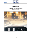
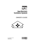
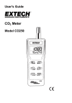
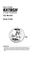
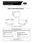
Energy Recovery Ventilator ERV ERVXXNVA Owner’s Guide SAFETY CONSIDERATIONS Recognize safety information. This is the safety--alert symbol When you see this symbol on the unit and in instructions or manuals, be alert to the potential for personal injury. Understand these signal words; DANGER, WARNING, and CAUTION. These words are used with the safety--alert symbol. DANGER identifies the most serious hazards which will result in severe personal injury or death. WARNING signifies hazards which could result in personal injury or death. CAUTION is used to identify unsafe practices which would result in minor personal injury or product and property damage. NOTE is used to highlight suggestions which will result in enhanced installation, reliability, or operation. ! WARNING ELECTRICAL OPERATION HAZARD Failure to follow this warning could result in personal injury or death. Before servicing system, always turn off main power to system. Turn off accessory heater power if applicable. There may be more than one disconnect switch. ! CAUTION PERSONAL INJURY HAZARD Failure to follow this caution may result in personal injury. A13212 Fig. 1 -- ERVXXNVA Although special care has been taken to minimize sharp edges in the construction of your unit, be extremely careful when handling parts or reaching into the unit. NOTE TO EQUIPMENT OWNER: For your convenience, please record the model and serial numbers of your new equipment in the spaces provided. This information, along with the installation data and dealer contact information will be helpful should your system require maintenance or service. INSTALLATION INFORMATION: ENERGY RECOVERY VENTILATOR Model # ERVXXNVA1090 Date Installed ________________________________ Serial # ______________________________________ DEALERSHIP CONTACT INFORMATION: Company Name_______________________________ ACCESSORIES (List type and model #) Address______________________________________ _____________________________________________ _____________________________________________ _____________________________________________ _____________________________________________ Technician Name _____________________________ _____________________________________________ _____________________________________________ Phone Number _______________________________ NOTE TO INSTALLER: This manual must be left with the equipment owner. ERV UNIT OPERATION Today’s houses are constructed using energy--saving building practices and technologies. These practices and innovations help reduce your utility bills, but prevent the introduction of fresh air. Without ventilation, stale air and contaminants remain in the air for extended periods of time. Stale, unhealthy air is generated from a variety of sources including everyday living functions, cooking, cleaning, painting, exhaust from attached garages, and off--gassing of chemicals used in construction and furnishings. Your ERV brings in fresh air and circulates it through your home around the clock and expels stale air to help reduce the stuffy effects of trapped indoor air. The actual rate of ventilation is determined by the size of your home, the number of bedrooms, and applicable local or national ventilation codes. Your installing contractor has selected and set an internal fan speed in the ERV to meet these fresh air requirements. This unit is normally installed without a separate wall--mounted control. It is generally wired directly to your furnace or fan coil unit. The blower motor in the furnace or fan coil works in conjunction with the two blowers in the ERV to circulate the air through the ERV and duct system. There are no controls, settings, or functions that need to be adjusted or changed by the homeowner. Continuous ventilation is provided when your thermostat is set to the constant fan mode. Front Door (Remove for access to core and filters.) Filters Heat Exchanger Core A13213 MAINTENANCE Fig. 3 -- ERVXXNVA Components 1. The motors are factory lubricated. Lubricating the bearings is not recommended. 2. A dirty air filter will cause excessive strain on the blower motor. The filters in your ERV are washable and should be cleaned every three months. Use a vacuum cleaner to remove the heaviest portion of accumulated dust, then wash in warm water. NOTE: Do NOT clean these filters in a dishwasher or dry them with heating appliances as they will be permanently damaged. Use lukewarm water to clean filters, then air dry. Replace filters only when they are completely dry. 3. The core should be vacuumed every three months to remove dust that would inhibit the energy transfer. Do not use water. The core should only be serviced when the outdoor temperature is between 60F (16C) and 75F (24C) and dry. NOTE: If the edges of the core are soft, do not try to service the core. The air passages can be damaged and/or closed off by handling it or trying to remove it. 4. Regularly check the screen on the exterior intake hood and clean as necessary. BEFORE YOU REQUEST A SERVICE CALL S Check the main power disconnect switch. Verify that the circuit breakers are ON or that fuses have not blown. If you must reset breakers or replace fuses, do so only once. Contact your servicing dealer for assistance if the breakers trip or the fuses blow a second time. S Check for sufficient airflow. Check air filters for accumulations of large particles. Check for blocked exhaust--air grilles or ductwork. Keep grilles and duct work open and unobstructed. If your ERV still fails to operate properly, contact your servicing dealer. Give the dealer your model and serial number. With this information, the dealer will be able to correct any problems. NOTE: During cold weather operation, it is possible for a small amount of frost to accumulate on the heat exchange core inside the ERV. If a large amount of frost or icing is present on the core, ventilation performance will be reduced, and melting ice or frost from the core may result in water damage. If you see a large amount of ice or frost on the core, or water dripping from or underneath the ERV, contact your installing contractor. INLET HOOD EXHAUST HOOD A13270 Fig. 2 -- Inlet/Exhaust Ventilation Copyright 2013 Carrier Corp. S 7310 W. Morris St. S Indianapolis, IN 46231 Edition Date: 05/13 Manufacturer reserves the right to change, at any time, specifications and designs without notice and without obligations. 2 Catalog No: OG ---ERVNVA ---01 Replaces: NEW