1
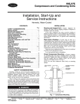
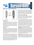
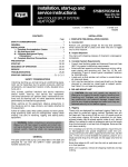
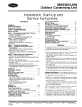
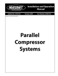
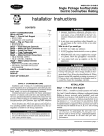
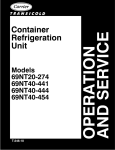
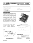
06E,07E
Compressors and Condensing Units
Installation, Start-Up and
Service Instructions
Hermetic, Water-Cooled
CONTENTS
INSTALLATION
Page
SAFETY CONSIDERATIONS . . . . . . . . . . . . . . . . . . . . . . 1
INSTALLATION . . . . . . . . . . . . . . . . . . . . . . . . . . . . . . . . . 1-6
Receive and Inspect Unit . . . . . . . . . . . . . . . . . . . . . . . . . 1
Place Unit in Position . . . . . . . . . . . . . . . . . . . . . . . . . . . . 1
Check Compressor Mounting . . . . . . . . . . . . . . . . . . . . 1
Piping Connections . . . . . . . . . . . . . . . . . . . . . . . . . . . . . . 2
Electrical Connections . . . . . . . . . . . . . . . . . . . . . . . . . . . 2
PRE-START-UP . . . . . . . . . . . . . . . . . . . . . . . . . . . . . . . . . .7,8
Evacuate, Dehydrate, and Leak Test. . . . . . . . . . . . . . 7
Oil Charge. . . . . . . . . . . . . . . . . . . . . . . . . . . . . . . . . . . . . . . . 7
START-UP . . . . . . . . . . . . . . . . . . . . . . . . . . . . . . . . . . . . . . . . 8
Start Compressor . . . . . . . . . . . . . . . . . . . . . . . . . . . . . . . . 8
Timer Functions. . . . . . . . . . . . . . . . . . . . . . . . . . . . . . . . . . 8
SERVICE . . . . . . . . . . . . . . . . . . . . . . . . . . . . . . . . . . . . . . 9-18
Protection Devices . . . . . . . . . . . . . . . . . . . . . . . . . . . . . . . 9
Compressor Thermal Protection . . . . . . . . . . . . . . . . . 9
Capacity Control System . . . . . . . . . . . . . . . . . . . . . . . . . 9
Removing, Inspecting and Replacing
Components . . . . . . . . . . . . . . . . . . . . . . . . . . . . . . . . . . 10
Lubrication System . . . . . . . . . . . . . . . . . . . . . . . . . . . . . 13
Cylinder Heads. . . . . . . . . . . . . . . . . . . . . . . . . . . . . . . . . . 14
Pressure Relief Valve. . . . . . . . . . . . . . . . . . . . . . . . . . . . 14
Suction and Discharge Valve Plate Assembly . . . 14
Terminal Plate Assembly . . . . . . . . . . . . . . . . . . . . . . . . 14
Compressor Running Gear Removal . . . . . . . . . . . . 14
Compressor Running Gear Replacement. . . . . . . . 15
Motor Removal . . . . . . . . . . . . . . . . . . . . . . . . . . . . . . . . . . 16
Motor Replacement . . . . . . . . . . . . . . . . . . . . . . . . . . . . . 16
Motor Burnout (Clean-Up Procedure). . . . . . . . . . . . 17
Condenser Maintenance . . . . . . . . . . . . . . . . . . . . . . . . 17
Receive and Inspect Unit — Inspect shipment for
damage. File claim with the shipping company if shipment is
damaged or parts are missing.
Local water conditions can cause excessive fouling or
pitting of condenser tubes. If such conditions are anticipated, a
water treatment analysis is recommended. Refer to Carrier
System Design Manual, Part 5, for general water conditioning
information.
SAFETY CONSIDERATIONS
Installing, starting up, and servicing this equipment can be
hazardous due to system pressures, electrical components, and
equipment location (roofs, elevated structures, etc.). Only
trained, qualified installers and service mechanics should
install, start up, and service this equipment.
When working on the equipment, observe precautions in the
literature, tags, stickers and labels attached to the equipment,
and other safety precautions that apply. Follow all safety codes.
Wear safety glasses and work gloves. Use care when handling,
rigging, and setting bulky equipment.
Electrical shock can cause personal injury and even death.
Be sure power to equipment is shut off before installing or
servicing this equipment. There may be more than one disconnect. Tag disconnect(s) to alert others not to turn power
on until work is completed.
Place Unit in Position — Locate unit on floor in a
well-ventilated area. Install unit where it will be warmer than
conditioned area. Position it to allow sufficient space for refrigerant and water connections and to service compressor. Allow
space at one end of condenser for tube cleaning or replacement.
Place unit so suction and discharge valves can be easily
reached and so oil level can be checked.
Make provision in piping layout to drain and vent condenser
if system is to be shut down in winter.
Level unit and bolt firmly to foundation.
Check Compressor Mounting — Loosen compressor mounting bolts and remove shipping blocks from under
compressor. Tighten all 4 bolts on compressor. Loosen each
bolt just enough until the flanged washer can be moved
sideways with finger pressure. See Fig. 1.
NOTE: Be sure that compressor floats freely on mounting
springs.
SELF-LOCKING
BOLT
SNUBBER FLANGED
WASHER
NEOPRENE
SNUBBER
COMPRESSOR FOOT
ISOLATION SPRING
Fig. 1 — Compressor Mounting
Manufacturer reserves the right to discontinue, or change at any time, specifications or designs without notice and without incurring obligations.
PC 802
Catalog No. 530-601
Printed in U.S.A.
Form 06/07E-1SI
Pg 1
5-01
Replaces: 06E,07E-9SI
Book 2 2 4 4
Tab 1b 2a 2b 3a
Piping Connections — Attach water supply and return
lines to connections indicated on condensing unit (Fig. 2).
Water leaving condenser should not be connected directly into
sewer lines; check local codes.
Attach refrigerant liquid and suction lines to condensing
unit (Fig. 2); suction and discharge lines to compressor unit
(Fig. 3 and 4). Discharge line muffler and check valve are
factory supplied with 06E compressor units. Install the muffler
as close to shutoff valve as possible and install the check valve
in the discharge line close to the muffler, on the downstream
side. When soldering or brazing piping to valves, disassemble
the valve or wrap it in wet cloth to prevent damage by heat.
Allow flexibility in suction line so compressor suction valve
may be moved aside for access to suction strainer.
A solenoid valve is necessary for single pumpout control
used on 06E and 07E units. Install the valve (field supplied) in
the liquid line, just before expansion valve. A filter drier of
adequate size should be installed in liquid line between condenser and solenoid valve.
Pressure relief valve located on top of condenser will open
to relieve excessive pressure, allowing refrigerant to escape.
Most local codes require piping from valve to outdoors.
Refer to Carrier System Design Manual for standard piping
techniques.
243 + 236 + 238
3
717
=
3
= 239 volts
Average Voltage =
Determine maximum deviation from average voltage:
(AB) 243 – 239 = 4 volts
(BC) 239 – 236 = 3 volts
(AC) 239 – 238 = 1 volt
Maximum deviation is 4 volts. Determine % voltage
imbalance:
4
% Voltage Imbalance = 100 x
= 1.7%
239
This amount of phase imbalance is satisfactory as it is below
the maximum allowable 2%.
IMPORTANT: If the supply voltage phase imbalance is
more than 2%, contact your local electric utility company
immediately. Allowing the unit to operate with a voltage
imbalance in excess of 2% may void the warranty.
POWER SUPPLY — Field wiring must comply with local
and national codes. See Table 1.
Install a branch circuit fused disconnect of adequate size to
handle starting current. The disconnect must be within sight
from the unit and readily accessible, in compliance with
National Electrical Code (NEC), Section 440-14.
Line power is brought into control center through indicated
opening. Connect line power supply to terminal block TB1;
connect power leads to terminals L1, L2 and L3. Connect
control circuit power supply (115 volts) to terminals 1 and 15
on terminal block TB2. Refer to Fig. 5.
Wiring connections for field-supplied equipment are shown
on wiring diagram. See Fig. 5.
ACCESSORIES — Field-installed accessories for the 06E
and 07E units are control circuit transformer and gage
panel (3 gages). Refer to accessory literature for installation instructions.
Electrical Connections
UNBALANCED 3-PHASE SUPPLY VOLTAGE — Never
operate a motor where a phase imbalance in supply voltage
is greater than 2%. Use the following formula to determine
the % voltage imbalance:
% Voltage Imbalance =
max voltage deviation from avg voltage
100 x
average voltage
Example: Supply voltage is 240-3-60
AB = 243 volts
BC = 236 volts
AC = 238 volts
2
3
VOLTS
208/230
460, 575
208/230
460, 575
208/230
460, 575
208/230
460, 575
A
66
66
78
78
78
78
691/2
691/2
B
493/4
433/4
493/4
433/4
493/4
433/4
493/4
493/4
C
23/4
23/4
23/4
23/4
23/4
23/4
23/4
23/4
D
34
34
34
34
34
34
34
34
E
271/2
26
271/2
26
271/2
26
271/2
271/2
F
1
1
1
1
1
1
1
1
Fig. 2 — 07E Water-Cooled Condensing Units
NOTES:
1. Recommended service space for removal of motor at
compressor motor end is 3 ft.
2. Recommended service space for removal of tube is one
condenser length at either end.
D044
B033
B027
A022
UNIT 07E
DIMENSIONS (in.)
G
21
21
21
21
21
21
21
21
H
59/16
59/16
59/16
59/16
59/16
59/16
41/8
41/8
I
95/16
95/16
95/16
95/16
95/16
95/16
85/8
85/8
NOTE: Recommended service space is 3 ft-0 in.
at compressor motor end to allow for motor
removal.
DIMENSIONS (in.)
06E UNIT
V022
W027
W033
W044
VOLTAGE
208/230
460,575
208/230
460,575
208/230
460,575
208/230
460,575
A
481/4
481/4
501/4
501/4
501/4
501/4
501/4
501/4
B
35
29
35
29
35
29
35
35
C
367/8
367/8
367/8
367/8
367/8
367/8
367/8
367/8
D
11/2
11/2
11/2
11/2
11/2
11/2
11/2
11/2
Fig. 3 — 06E Hermetic Compressor Units
Fig. 4 — 06E Compressors
4
E
271/2
26
271/2
26
271/2
26
271/2
271/2
F
1
1
1
1
1
1
1
1
G
191/2
191/2
191/2
191/2
191/2
191/2
191/2
191/2
Table 1 — Electrical Data — Compressor Motor With Circuit Breaker
COMPRESSOR MOTOR DATA
Compressor
Voltage
Part
(3 Ph - 60 Hz) Hp
Number 06E
250
265
A
275
299
LRA
MHA
MTA
PW
RLA
XL
—
—
—
—
—
—
208/230
575
460
208/230
575
460
208/230
575
460
208/230
575
460
20
25
30
40
CIRCUIT BREAKER
Motor
Maximum
LRA-PW
Recommended
Maximum
Winding
Recommended
Must Trip
LRA-XL
(first
RLA
Resistance Circuit Breaker MHA MTA LRA
RLA
Amps
winding)
Part
No.
(Ohms)
108
87
345
207
0.32
HH83XB336
91 104 350
74.3
45
36
120
72
2.2
XA461
33
38 124
27.1
54
44
173
104
1.3
XA424
42
49 175
35.0
140
112
446
268
0.27
HH83XC509
110 127 420
90.7
57
46
164
98
1.6
XA469
46
53 164
37.9
70
56
223
134
1.1
XA426
55 643 210
45.7
168
135
506
304
0.22
HH83XC539
142 163 507
116.4
65
52
176
106
1.3
XA430
50
58 168
41.4
84
68
253
152
0.9
XA425
63
73 210
52.1
236
189
690
414
0.15
HH83XC537
187 215 636
153.6
94
75
276
165
1.0
XA551
74
85 236
60.7
118
95
345
207
0.58
XA550
92 106 295
75.7
LEGEND
Locked Rotor Amps
Must Hold Amps
Must-Trip Amps
Part-Winding (Start)
Rated Load Amps
Across-the-Line (Start)
4. Recommended RLA value shown is determined by: circuit
breaker must trip value ÷ 1.40. Use this recommended (and
minimum) RLA value to determine nameplate stamping, minimum contactor sizing, and wire sizing. RECOMMENDED RLA
FOR 06E COMPRESSORS EQUALS: MUST-TRIP (MTA) OF
CARLYLE APPROVED OVERCURRENT DEVICE BEING
USED ÷ 1.40
5. Compressor operating amps at any specific condition can only
be determined from a performance curve.
6. Ohm values for resistance are approximate and shown for reference purposes only. Motors from different vendors and
motors of different efficiencies can differ up to 15% from data
shown.
7. Electrical data for compressor part numbers 06ER, 06EM and
50 Hz models (not shown) are available from Carrier Sales
Representative.
*Refer to physical data table to match compressor with correct compressor or water-cooled condensing unit.
NOTES:
1. Compressor MTA and RLA values are maximum figures.
2. LRA values for PW second winding = 1/2 the LRA – XL value.
3. 3-Pole XL circuit breakers shown, other 3-Pole XL alternates
and 6-Pole PW breakers available. Terminal lugs for circuit
breakers available in package 06EA660152 (not shown).
C1
C2
CCB
CHR
CR
FU
GND
HPS
LPS
NEC
NEMA
—
—
—
—
—
—
—
—
—
—
—
OPS
POR
TB
TDR
TM
TR
—
—
—
—
—
—
LEGEND
Compressor Contactor
Compressor Contactor (PW)
Compressor Circuit Breaker
Crankcase Heater Relay
Control Relay
Fuse
Ground
High-Pressure Switch
Low-Pressure Switch
National Electrical Code
National Electrical
Manufacturer’s Association
Oil Pressure Switch
Pumpout Relay
Terminal Block
Time Delay Relay
Timer Motor
Timer Relay
Fig. 5 — Component Location
5
LEGEND
AUX — Auxiliary
C
— Compressor Contactor
C1
— Compressor Contactor
(XL start and first step of PW start)
C2
— Compressor Contactor
(PW second step)
CH
— Crankcase Heater
CHR — Crankcase Heater Relay
CR
— Control Relay
DTS — Discharge Temperature Sensor
DX
— Direct Expansion
FU
— Fuse
HPS — High-Pressure Switch
LLS — Liquid Line Solenoid Valve
LPS — Low-Pressure Switch
M1
M2
M3
NEC
OPS
POR
PW
SW
TB
TDR
TM
TR
XL
— Evaporator Fan or
Chilled Water Pump
— Cooling Tower Pump
— Cooling Tower Fan
— National Electrical Code
— Oil-Pressure Switch
— Pumpout Relay
— Part Wind
— Start-Stop-Reset Switch
— Terminal Block
— Time Delay Relay
— Timer Motor
— Timer Relay
— Across-the-Line
NOTES:
1. Factory wiring is in compliance with NEC. Any field modifications
or additions must be in compliance with all applicable codes. Use
copper, copper-clad aluminum for field power supply only.
2. Field power supply wiring must be 75 C minimum.
3. Compressor thermally protected. Three-phase motors are protected against primary single-phasing condition.
4. Pilot duty control must be field supplied. Minimum contact rating
must be 25 va.
5. 60 Hz units have 120 volt control circuit. 50 Hz units have 230 volt
control circuit. A separate source of supply at the correct voltage
must be field supplied supply at the through a fused disconnect
6.
7.
8.
9.
10.
Unmarked Terminal
Marked Terminal
Factory Wiring
Field Control Wiring
To indicate common potential only;
not to represent wiring.
Splice
device with a maximum rating of 15 A to TB2 connections L1
(Hot Side) and L2 (Neutral).
Open control circuit disconnect switch for servicing only. Disconnect must remain closed for crankcase heater to operate.
A transformer of the following rating may be field supplied for
60 Hz units: 350 va.
Transformer must be fused and grounded per applicable codes.
If any of the original wiring furnished must be replaced, it must be
replaced with 90 C wire or its equivalent.
Wiring is shown for single pumpout control. Single pumpout
control should not be used on direct-expansion (DX) cooler applications (see lower diagram for wiring when applied with DX
cooler).
Fig. 6 — Control Circuit Wiring for 06E/07E Units
6
Terminal Block Connector
PRE-START-UP
operation. To add or remove oil, see Carrier Standard Service
Techniques Manual, Chapter 1, Refrigerants.
IMPORTANT: Use only Carrier approved compressor oil.
Do not reuse oil that has been drained and do not use oil
that has been exposed to atmosphere.
When charging, or when removing charge, circulate water
through water-cooled condenser and cooler continuously to
prevent freezing. Freezing damage is considered abuse and
is not covered by Carrier warranty.
Approved compressor oils*:
Petroleum Specialties, Inc. . . . . . . . . . . . . . . . . . . . . . Cryol 150
Texaco, Inc. . . . . . . . . . . . . . . . . . . . . . . . . . . . . Capella WR-32
Witco Chemical Co.. . . . . . . . . . . . . . . . . . . . . . . . . Suniso 3GS
Evacuate, Dehydrate, and Leak Test — The entire
refrigerant system must be evacuated, dehydrated and leak tested by methods described in Carrier Standard Service Techniques Manual, Chapter 1, Section 1-6 and 1-7. Use sight glass
method to charge system. See Section 1-8 of Service Techniques Manual for details.
Charge the system to a clear sight glass while holding
saturated condensing pressure constant at 125 F (air-cooled
systems) or 105 F (water-cooled systems). Add additional
refrigerant to fill condenser subcooler coils for air-cooled
applications.
*Approved for R-12, R-22, R-502 refrigerants. Contact Carrier
Factory Sales Representative for other refrigerants.
TO ADD OIL — Close suction shutoff valve and pump down
crankcase to 2 psig. (Low-pressure cut-out must be bypassed.)
Wait a few minutes and repeat as needed until pressure remains
at 2 psig. Remove oil fill plug above bull’s-eye, add oil through
plug hole and replace plug. Run compressor for about 20 minutes and check the oil level.
TO REMOVE OIL — Pump down compressor to 2 psig.
Loosen the 1/4-in. pipe plug in compressor base and allow the
oil to seep out past the threads of the plug. The crankcase will
be under slight pressure. Be careful not to remove the plug; the
entire oil charge may be lost.
Oil Charge (See Tables 2 and 3) — All units are
factory charged with oil. If oil is visible in sight glass, start
compressor. Observe level and add oil, if required, to bring
level in crankcase 1/8 to 3/8 of bull’s-eye during steady
Table 2 — 06E Physical Data
UNIT 06E
OPERATING WEIGHT (lb)
REFRIGERANT
COMPRESSOR — 06E*
Cylinders
Bore (in.)
Stroke (in.)
Displacement (cfm at 1750 rpm)
Maximum Rpm
Oil Charge (pt)
High Side Maximum Pressure (psi)
Low Side Maximum Pressure (psi)
CONNECTIONS (in.)
Suction Valve (ODF)
Discharge Valve (ODF)
V022
600
W027
W033
640
650
R-134a, R-22, R-507/404A
A265
A275
6
6
211/16
211/16
2
23/16
68
75
1750
19
19
450 PSIG
245 PSIG
A250
4
211/16
23/16
50
14
15/8
11/8
15/8
13/8
LEGEND
ODF — Outside Diameter Female
*Compressors listed are for R-22 applications. For R-134a an 06EM compressor
is standard offering; an 06ER compressor is standard for R-507/404A. Factory
compressor substitutes may be made. Contact Carrier Sales Representative.
7
21/8
13/8
W044
670
A299
6
211/16
27/8
99
19
21/8
15/8
Table 3 — 07E Physical Data
UNIT 07E
OPERATING WEIGHT (lb)
REFRIGERANT
COMPRESSOR — 06E*
Cylinders
Bore (in.)
Stroke (in.)
Displacement (cfm at 1750 rpm)
Oil Charge (pt)
High Side Maximum Pressure (psi)
Low Side Maximum Pressure (psi)
CONDENSER (Shell and Tube)† Part Number
Refrigerant Storage
Capacity (lb)
R-134a
R-22
Min Refrigerant Operating
Charge (lb)
R-507/404A
A022
1090
A250
4
211/16
23/16
50
14
P701-0840AX
71.3
15.4
70.4
15.1
61.1
15.1
REFRIGERANT CONNECTION (in. ODF)
Inlet
Outlet
WATER CONNECTION (in. FPT)
Inlet/Outlet
B027
B033
1200
1250
R-134a, R-22, R-507/404A
A265
A275
6
6
211/16
211/16
2
23/16
68
75
19
19
450
245
P701-0850AX P701-0850AX
85.90
85.90
18.67
18.67
84.80
84.80
18.30
18.30
73.60
73.60
18.30
18.30
D044
1410
A299
6
211/16
27/8
99
19
P701-1065AX
112.70
23.77
111.20
23.30
96.50
23.30
21/8
13/8
21/8
13/8
21/8
13/8
25/8
15/8
21/2
21/2
21/2
3
LEGEND
FPT — Female Pipe Thread
ODF — Outside Diameter, Female
*Compressor listed is the standard compressor for R-22, air conditioning duty. An 06ER compressor is standard equipment
for low temperature (R-507/404A) applications. For medium temperature (R-134a) applications, an 06EM compressor is
standard. Factory substitutions may be made. Contact Carrier Sales Representative.
†The condenser listed is for R-22, air conditioning duty and may change based on the application. Maximum condenser
operating pressure: 350 psi refrigerant side, 150 psi water side.
START-UP
Timer Functions (See Fig. 7 — Timer Cycle.)
1. Switch A (contacts A-A1 and A-A2) provides Time
Guard® function. Start of compressor is delayed approximately 5.5 minutes after shutoff. The minimum time
between starts of compressor is 8 minutes.
2. Switch B (contacts B-B1 and B-B2) starts compressor
and deenergizes the crankcase heater. These contacts also
provide one-second time delay for part-winding start.
3. Switch E (contacts E-1) provides approximately
40-second bypass of oil pressure switch (OPS) at start-up.
Compressor will shut off if sufficient oil pressure does
not build up.
4. Switch D (contacts D-D1) bypasses the low-pressure
switch (LPS) for 2.5 minutes at start-up for winter start
control.
Energize crankcase heater at least 24 hours prior to start-up.
Check to see that oil level is approximately 1/3 up on the
compressor sight glass.
Open water supply valve and allow water to reach condenser. (Turn condenser fan on when the compressor unit is applied
with air-cooled condenser.)
Backseat the compressor suction and discharge shutoff
valves; open liquid line valve at receiver.
Start evaporator fan or chilled water pump.
Do not attempt start-up with terminal cover removed from
compressor. Bodily injury or death may result from
explosion and/or fire if power is supplied to compressor
with the terminal cover removed or unsecured. See
warning label on terminal cover.
Start Compressor — Push the control circuit STARTSTOP-RESET switch to START. The timer motor starts
immediately. Depending on the position of the timer, the
compressor start is delayed for 12 seconds to approximately
8 minutes. Check oil pressure after compressor has run a few
minutes; the pressure should be 12 to 18 psi above the suction
pressure. After about 20 minutes of operation, stop the compressor. Allow it to be idle for about 5 minutes, then observe
the oil level in the sight glass. Refer to the Carrier Standard
Service Techniques Manual, Chapter 1, Section 1-11, for
adding oil. The proper oil level for the 06E compressor is
approximately 1/3 up on sight glass.
Fig. 7 — Timer Cycle
8
SERVICE
exceeds 295 ± 5 F, the sensor contacts open and the compressor
shuts down. The sensor reset temperature is 235 F minimum.
See Fig. 8 for control circuit connections.
Protection Devices
HIGH-PRESSURE SWITCH — Check by throttling condenser water or blocking airflow on air-cooled units, allowing
head pressure to rise gradually. Check discharge pressure
constantly throughout procedure. Compressor should shut off
within 10 psi of values shown in Table 4.
LOW-PRESSURE SWITCH — Check by slowly closing
suction shutoff valve or by completely closing liquid line
shutoff valve. A decrease of suction pressure will follow.
Compressor should shut off within 4 psi of values shown in
Table 4.
OIL PRESSURE SWITCH (OPS) — The oil pressure switch
protects against damage from loss of oil or loss of oil pressure
during unit start-up. If the oil pressure differential sensed by the
OPS is 6 psig or less on unit start-up, the switch remains closed
and the OPS heater is energized.
The switch time delay is approximately 45 seconds. If after
45 seconds the oil pressure differential sensed by the OPS is
less than 11 psig, the heater remains energized. The OPS
temperature actuated switch then opens and the compressor is
deenergized. If the differential reaches 11 psig, the OPS opens
and deenergizes the heater and the system operates normally.
See Table 4.
Capacity Control System
CAPACITY CONTROL VALVE (Fig. 9) — Valve is controlled by suction pressure and actuated by discharge pressure.
Each valve controls 2 cylinders. On start-up, controlled
cylinders do not load up until differential between suction and
discharge pressures is approximately 25 psi. See Table 5.
IMPORTANT: Do not use automatic pumpdown control
on 06E,07E units equipped with unloader valves. Use
single pumpout or solenoid drop (minimum protection)
control.
CAPACITY CONTROL VALVE ADJUSTMENTS
Control Set Point (Cylinder Load Point) — Adjustable from
0 to 86 psig. Pressure differential between cylinder load-up
point and cylinder unload point is adjustable from 6 psi
to 16 psi.
CR
4
6
RED
C1
C2
C2
C2
YEL
C1
BLU
TIMER
CONTACTS
IMPORTANT: If the oil pressure switch causes unit lockout, determine and correct the cause of the lockout (such as
loss of compressor oil or flooded compressor) before
restarting the unit. Failure to correct the cause of OPS
lockout may constitute abuse. Equipment failure due to
abuse is not covered by warranty.
B2
DTS
B
ORN
BLU
TB2
B1
C
CR
DTS
TB
To restart the unit, push the OPS reset button and then push
the control circuit switch on the unit control box to OFF and
then to ON.
•
—
—
—
—
6
LEGEND
Compressor Contactor
Control Relay
Discharge Temperature Sensor
Terminal Block
Splice (in compressor junction box)
Fig. 8 — Discharge Temperature Sensor (DTS)
Table 4 — Factory Switch Settings
SWITCH TYPE
High Pressure
Low Pressure
Oil Pressure
PRESSURE CHANGE AFFECTING
SWITCH POSITION (psig)
Closed
Open
210 (±10)
290 (±10)
70 (±4)
60 (±4)
6
11
CONTROL
SET POINT
ADJUSTMENT
NUT
NOTES:
1. Values for the high- and low-pressure switches based on R-22.
For other refrigerants, reset to pressure corresponding to saturation temperatures indicated by the listed pressures.
2. Values for oil pressure are above operating suction pressure
(pressure differential between suction and discharge pressures
of oil pump).
TIME GUARD® CONTROL — The Time Guard control
protects against short cycling. See Start Compressor.
CRANKCASE HEATER — The crankcase heater prevents
absorption of liquid refrigerant by oil in crankcase during brief
or extended shutdown periods. Source of 115-volt power is the
auxiliary control power, independent of the main unit power.
This assures compressor protection even when main unit
power disconnect switch is off.
VALVE BODY
IMPORTANT: Never open any switch or disconnect that
will deenergize the crankcase heater unless unit is being
serviced or is to be shut down for a prolonged period. After
a prolonged shutdown or a service job, energize the crankcase heater for 24 hours before starting the compressor.
SEALING CAP
(COVERS PRESSURE DIFFERENTIAL
ADJUSTMENT SCREW)
Compressor Thermal Protection — A discharge
Fig. 9 — Capacity Control Valve
temperature sensor, installed in one cylinder head, detects an
overtemperature condition. If the discharge temperature
9
Replacing Suction Cutoff Unloading Heads — When the
original compressor is equipped with suction cutoff unloading
head(s), the complete cylinder head and control valve assemblies must be transferred to the service (replacement) compressor. See Fig. 10 for typical suction cutoff installation. Where
one step of unloading is required, remove the bypass-type
unloader head and valve plate assembly from replacement
compressor (cylinder head next to terminal box). Remove
check valve from the valve plate. Using new gaskets, reinstall
the valve plate assembly and install the suction cutoff head
from the original compressor. Torque the cylinder head
holddown bolts to 90 to 100 lb-ft. For 6-cylinder 2-step suction
cutoff unloading, transfer the second unloading head and
control valve from the original compressor to the replacement
compressor, using the valve plate assembly from the replacement compressor. Use new gaskets.
Be sure the new cylinder head gasket is the one shown in
Fig. 11, Item 33, when installing suction cutoff unloader head.
Install parts removed from replacement compressor on
original compressor and seal all openings to prevent
contamination.
To Regulate Control Set Point — Turn adjustment nut
clockwise to its bottom stop. In this position, set point is
86 psig. Control set point is then regulated to desired pressure
by turning adjustment nut counterclockwise. Each full turn
decreases set point by approximately 7.2 psi. Approximately
12 turns counterclockwise lowers the control set point to
0 psig. See Table 5.
Table 5 — Capacity Control
UNIT 06E,07E
ALL 4 CYLINDER
MODELS
ALL 6 CYLINDER
MODELS
NO. OF
CONTR
CYL
% Full Load Capacity
100
67
49
32
% Full Load kW
100
73
57
46
Number of Active Cylinders
2
4
—
2
—
4
6
4
—
2
NOTE: Capacity control valve factory settings for 4-cylinder units
are: 59 psig control set point (cylinder load point), 10 psi differential
(59 psig cylinder unload point). Settings for 6-cylinder units are: left
cylinder bank control set point is 70 psig, differential is 10 psi; right
cylinder bank control set point is 68 psig, differential is 10 psi.
Removing, Inspecting and Replacing
Components (Fig. 11)
Pressure Differential Adjustment — Turn differential adjusting screw counterclockwise to its back-stop position. In this
position, differential is 6 psi. Pressure differential is set by
turning adjusting screw clockwise. Each full turn increases
pressure differential by approximately 0.8 psi. Approximately
10 turns increases differential to 16 psi.
SUCTION CUTOFF UNLOADER OPERATION — The capacity control valve shown in Fig. 9 is the pressure operated
type. Refer to Fig. 10 and the following description for valve
operation.
Loaded — When suction pressure rises high enough to overcome control set point spring, the diaphragm snaps to the left
and relieves pressure against the poppet valve. The drive spring
moves poppet valve to the left and it seats in the closed
position. See Fig. 10.
With poppet valve closed, discharge gas is directed into the
unloader-piston chamber and pressure builds up against the
piston. When pressure against unloader piston is high enough
to overcome the unloader valve spring, piston moves valve to
the right, opening suction port. Suction gas can now be drawn
into the cylinders and the bank is running fully loaded.
Unloaded — As suction pressure drops below set point, control spring expands, snapping diaphragm to right. This forces
poppet valve open and allows gas from discharge manifold to
vent thru base of control valve to suction side. Loss of full
discharge pressure against unloader piston allows unloader
valve spring to move valve left to closed position. The suction
port is blocked, isolating the cylinder bank from the suction
manifold. The cylinder bank is now unloaded. See Fig. 10.
Service Replacement Compressors — These compressors are
not equipped with capacity control valves. One side-bank
cylinder head is a bypass unloading type, plugged with a
spring-loaded piston plug assembly. As received, the compressor will run fully loaded.
Do not remove the compressor terminal box cover until all
electrical power is disconnected and pressure is relieved.
Terminal pins may blow out causing injuries, death, and/or
fire.
SERVICE NOTES
1. All compressors have interchangeable valve plate assemblies, unloader valves and oil pump bearing head
assemblies. For replacement items use Carrier Specified
Parts.
2. Before compressor is opened, the refrigerant must be
removed from it by the Pumpdown method:
a. Start compressor, close suction shutoff valve, and
reduce crankcase pressure to 2 psig. (Bypass low
pressurestat with a jumper.)
b. Stop compressor and isolate from system by
closing discharge shutoff valve.
c. Bleed any residual refrigerant. Drain oil if
necessary.
3. After disassembly, clean all parts with solvent. Use
mineral spirits, white gasoline or naphtha.
4. Before assembly, coat all parts with compressor oil and
clean and inspect all gasket surfaces. Replace all gaskets
with new factory-made gaskets. See Table 6 for torque
values.
5. After reassembly, evacuate compressor and open suction
and discharge valves. Restart compressor and adjust
refrigerant charge.
10
NOTE: Pressure-operated control valve shown. A solenoid-operated control valve can also be used.
Fig. 10 — Suction Cutoff Unloader Operation
11
7
3
8
9
15 16 17 18
14
19
20
10
21
23
22
4
5
6
1
2
31
26
32
33
31
25
31
34
35
32
33
36
24
32
37
38
38
39
40
41
41
29
30
28
27
LEGEND
1
2
3
4
5
6
7
8
9
10
11
12
13
14
15
16
—
—
—
—
—
—
—
—
—
—
—
—
—
—
—
—
Stator (Compressor Motor)
Rotor (Compressor Motor)
Motor Key
Rotor Plate Washer
Rotor Lock Washer
Rotor Lock Bolt
Motor Lock Bushing
Roll Pin
Acorn Nut and Gasket
Compressor Crankcase
Bottom Cover Plate
Crankcase Oil Filter Screen
Pump End Bearing Head Assembly
Motor End Cover
Oil Sight Glass Assembly
Oil Sight Glass O-Ring Gasket
17
18
19
20
21
22
23
24
25
—
—
—
—
—
—
—
—
—
26
27
28
29
30
31
—
—
—
—
—
—
13
12
Oil Sight Glass Screw
Oil Sight Glass Lock Washer
Pipe Plug (Hex Head)
Crankshaft
Ring Spacer (when required)
Bearing Washer
Connecting Rod and Piston Assembly
Connecting Rod and Cap Assembly
Piston, Piston Pin and Retaining Ring
Package
Piston Rings (Oil and Compression)
Terminal Plate Assembly
Terminal Bolt Assembly
Terminal Box
Terminal Box Mounting Screw (4)
Suction Valve
11
32 — Valve Plate Assembly (includes discharge valves)
33 — Cylinder Head Gasket
34 — Cap Screw, Valve Stop
35 — Valve Stop Support
36 — Discharge Valve Stop
37 — Discharge Valve
38 — Cylinder Head (Capacity control,
side bank)
39 — Cylinder Head (Center bank)
40 — Cylinder Head Bolt (8 per head)
41 — Capacity Control Valve (Pressure
type shown)
Fig. 11 — Compressor Components (06E Shown)
12
Table 6 — Torque Values
REMOVE 8 CAP
SCREWS
SIZE
TORQUE
THREADS
DIAM
RANGE
USAGE
PER IN.
(in.)
(lb-ft)
1/
27 (pipe)
8-12
Pipe Plug — Crankshaft
16
1/
18 (pipe)
20-25 Pipe Plug — Crankcase
4
8-10
Conn. Rod Cap Screw
1/
20
4
8-12
Junction Box
3-5
Sight Glass
14-18 Oil Pump Drive Segment
1/
28
14-18 Unloader Valve
4
14-18 Discharge Valve Stop
12-15 Head Gasket Positioning Screw
Cover Plate — Pump End Bearing
15-24
5/
18 (pipe)
Head
16
15-24 Discharge Service Valve (4 cyl)
30-40 Bottom Plate — Crankcase
30-40 Compressor Foot
3/
16
30-40 Terminal Plate
8
25-30 Oil Plug — Pump End Bearing Head
2-4
Terminal Bolts
3/
18 (pipe)
30-40 Pipe Plug — Junction Box
8
55-65 Motor End Cover
7/
14
16
55-65 Pump End Bearing Head
90-100 Cylinder Head
1/
13
90-120 Discharge Service Valve (6 cyl)
2
90-120 Suction Service Valve (4 cyl)
90-120 Suction Service Valve (6 cyl)
5/
11
8
90-120 Rotor Lock — Crankshaft
5/
18
60-75 Oil Drain Plug
8
3/
16
105
Stator Lock
4
32
1-2
Check Valve Body — Crankcase
No. 6
4-6
Oil Pump Drive Segment
32
No. 10
4-6
Terminal Screw
OIL
PRESSURE
TAP
PUMP END
BEARING HEAD
DRIVE SEGMENT
CAP SCREWS
OIL FEED GUIDE VANE
AND SPRING
COVER
PLATE
Fig. 12 — Removing Pump End Bearing Head
Lubrication System
TESTING OIL PUMP — An oil pressure tap is located above
oil pump cover plate (Fig. 12). Oil pressure should be 12 to
18 psi above suction pressure.
Oil Filter Screen — Screen is accessible through bottom cover
plate. Remove and inspect strainer for holes and dirt. Clean it
with solvent and replace.
OIL PUMP AND BEARING HEAD — The oil pump assembly is contained in the pump end bearing head aluminum
casting. (The pump end main bearing is a machined part of this
casing — no insert bearing.)
Remove Bearing Head — Remove bearing head from crankcase and disassemble oil pump. Drive segment cap screws
must be removed before bearing head can be removed
(Fig. 12). Remove pump vane assemblies from both sides of
the bearing head by pushing against the bearing side of the
rotor. Check all parts (Fig. 13) for wear and damage.
Replace Bearing Head
1. Install the rotor retaining ring in the ring groove of the
pump rotor with chamfered edge toward compressor.
Compress retaining ring, and insert pump rotor into
bearing head.
2. Place the pump vanes, pump vane spring with guides, and
snap rings into the bearing head. Compress the springs
and force the snap rings into their grooves. (Insert snap
rings with flat side against casting.)
3. Bolt bearing head to crankcase (use 55 to 65 lb-ft torque).
Bolt drive segment to crankshaft.
4. Insert the oil feed guide vane with large diameter inward.
Place oil feed guide vane spring over small diameter of
guide vane.
5. Install pump cover plate.
1
2
3
4
5
1
2
3
4
5
—
—
—
—
—
LEGEND
Pump End Bearing Head
Drive Segment
Oil Feed Guide Vane
Oil Feed Guide Vane Spring
Cover Plate
Fig. 13 — Pump End Bearing Head Assembly
13
Cylinder Heads (See Fig. 11) — Disassemble cyl-
Keep each connecting rod and piston assembly together for
proper reassembly. Check all parts and crankpins for wear
(refer to Table 7 for wear limits).
inder heads by removing cap screws, and prying up on side
lifting tabs to break heads loose from valve plates. Do not hit
cylinder heads to break loose.
Check heads for warping, cracks and damage to gasket
surfaces. When replacing cylinder head, torque cap screws
90 to 100 lb-ft (prevents high to low side leak in center portion
of cylinder head gasket).
Pressure Relief Valve — This internal safety device is
located in center cylinder bank (6-cylinder compressors,
Fig. 14) or under discharge service valve (4-cylinder compressors). The valve relieves refrigerant pressure from high to low
side at 400 psi pressure differential. Check valve for evidence
of leaking. Change if defective or if valve has ever opened due
to excessive pressure. Use a standard socket-type screwdriver
to remove and replace valve.
Suction and Discharge Valve Plate Assembly
TEST — Leak test for leaking discharge valves by pumping
compressor down and observing suction and discharge pressure equalization. If a discharge valve is leaking, pressures will
equalize rapidly. Maximum allowable discharge pressure drop
is 3 psi per minute.
If there is an indicated loss of capacity and discharge valves
check properly, remove suction and discharge valve plate
assembly and inspect suction valves.
DISASSEMBLE — Remove cylinder head.
1. Remove discharge valve assembly: cap screws, valve
stops, valve stop supports and valves.
2. Pry up on side lifting tab to remove valve plate and
expose suction valves (Fig. 15). Remove suction valves
and backers from dowel pins.
Inspect valves and valve seats for wear and damage (see
Wear Limits, Table 7). Replace valves if cracked or worn. If
valve seats are worn, replace complete valve plate assembly.
REASSEMBLE — Do not interchange valves. Install brackets and suction valves on dowel pins (backer is under the valve;
see Fig. 15). Place valve plate on cylinder deck and reinstall
discharge valve assembly. Retorque discharge valve stop cap
screws to 16 lb-ft. Replace cylinder head. (Be sure tab on
cylinder head gasket is lined up with tabs on cylinder head and
valve plate.)
PRESSURE RELIEF VALVE
Fig. 14 — Pressure Relief Valve Removal
VALVE PLATE
TAB
SUCTION
VALVE
BACKER
SECTION VALVE
SEATS
(VALVE PLATE)
SUCTION VALVES
TAB
(BACKER IS
UNDER THE
VALVE)
SUCTION VALVE STOPS
(CYLINDER DECK)
Terminal Plate Assembly — If there is a refrigerant
leak between the terminal plate and the compressor, remove
plate assembly and replace gasket.
If any terminal is shorted to the terminal plate, replace
complete plate assembly, using a new gasket.
Do not remove the terminal plate assembly except for the
above conditions.
REMOVAL — Remove junction box from terminal plate, and
remove cap screws holding terminal plate to compressor. Mark
all motor leads so they can be reassembled correctly to terminal
plate. Loosen Allen head screws holding motor leads to terminal plate (Fig. 16). Remove terminal plate.
REINSTALL — In reverse sequence, reinstall making sure
motor leads are correct. Torque terminal plate cap screws per
Table 6.
DOWEL
PINS
Fig. 15 — Valve Plate Removed
TERMINAL
PLATE
ASSEMBLY
Compressor Running Gear Removal
CONNECTING ROD/PISTON ASSEMBLY — Remove cylinder heads, valve plate assemblies, crankcase bottom cover
plate, oil filter screen, and connecting rod caps (Fig. 17). Label
caps and rods so they may be reinstalled in same place on
crankshaft. Push connecting rod and piston assemblies up
through cylinder deck. Disassemble connecting rods from
pistons by removing retaining rings and piston pins. Remove
oil and compression rings from piston.
ALLEN HEAD
SCREWS (1/4”)
Fig. 16 — Removing Terminal Plate Assembly
14
Compressor Running Gear Replacement
CRANKSHAFT — Be sure compressor end bearing washer is
in place on dowel pin. Install crankshaft through pump end,
carefully guiding it through main bearings. Replace rotor.
CONNECTING ROD/PISTON ASSEMBLY (Fig. 18) — The
assembly of the connecting rod with contoured-crown piston
must be as shown. Note the relationship of the piston crown
pattern with the chamfered side of the rod bearing. This ensures
that the rods in the outer positions on crankpins have the
chamfers toward crankpin fillets. On 6-cylinder compressors,
the position of the chamfer of center rod on crankpin has no
significance.
Lock the piston pin in place with retaining rings as shown in
Fig. 18.
The retaining rings should be tight enough that they cannot
be rotated by finger pressure.
Rings
1. Check ring gap by inserting each ring separately in cylinder approximately 3/8 in. from top. Ring gap should be
between 0.002 in. and 0.007 inch.
2. Install compression ring in top piston groove with either
side up (no difference). Install oil ring below compression
ring with notched end on bottom. Stagger ring gaps
180 degrees.
3. Measure side clearance between ring and piston
(Table 6). Check rings for free action.
Installation of Connecting Rod/Piston Assembly — Insert the
connecting rod/piston assemblies into cylinders with pistons
positioned as shown in Fig. 18 and 19.
This is necessary so that the suction valve and backer lie
properly over the contoured piston crown.
Be sure that the outer rod on each crankpin has the
chamfered side toward the crankpin fillet (this is a double
check on the connecting rod/piston assembly).
Install caps to matching connecting rods with chamfered
sides aligned. Caps are secured with Nylock cap screws.
Tighten with 8 to 10 lb-ft torque.
CRANKSHAFT
CONNECTING
RODS AND
CAPS
OIL DRAIN
PLUG
(MAGNETIC)
BOTTOM
COVER
PLATE
OIL FILTER
SCREEN
Fig. 17 — View with Bottom Cover Plate Removed
CRANKSHAFT — Remove pump end bearing head and
rotor. If connecting rod and piston assemblies are still in place.
remove connecting rod caps and push piston assembly up into
cylinder for crankshaft clearance. Pull crankshaft out through
pump end opening. Inspect crankshaft journals for wear and
tolerances shown in Table 7. Check oil passages and clean if
clogged.
PUMP END MAIN BEARING — This bearing is a machined
part of the oil pump and bearing head casting. Disassemble
bearing head. If bearing is scored or worn, replace the complete
bearing head.
CRANKCASE AND MOTOR END MAIN BEARINGS — These bearings are not field replaceable. If bearings
are worn or damaged, replace compressor.
TOWARD SUCTION VALVE
DOWELS IN CYLINDER DECK
Table 7 — Wear Limits — 06E Compressor
COMPRESSOR PART
MOTOR END
Main Bearing Diameter
Journal Diameter
PUMP END
Main Bearing Diameter
Journal Diameter
CONNECTING ROD
Bearing Diameter
(After Assembly)
Crankpin Diameter
THRUSTWASHER
(Thickness)
CYLINDERS
Bore
Piston Diameter
Wrist Pin Diameter
Con. Rod Wrist Pin ID
Piston Ring End Gap
Piston Ring Side Clearance
VALVE
Suction
THICKNESS
Discharge
END CLEARANCE
FACTORY TOL.
(in.)
Max
Min
MAXIMUM
ALLOWABLE
WEAR* (in.)
1.8760
—
—
1.8725
0.001*
1.6260
—
—
1.6233
0.001*
1.7515
—
—
1.7483
—
0.155
—
2.6885
—
—
0.8755
0.007
0.003
0.0315
0.0255
0.0225
0.031
—
2.6817
0.8748
—
0.002
0.001
0.0305
0.0245
0.0215
—
0.002
0.002
0.001
0.001
0.015
0.002
0.002*
RETAINING
RING GROOVE
(BOTH SIDES)
POSITION RETAINING
RING GAP APPROXIMATELY
ON THIS CENTERLINE
0.002
0.002
0.010
CHAMFER MUST
BE ON THIS SIDE
*Maximum allowable wear above maximum or below minimum factory
tolerances shown. For example: difference between main bearing diameter and journal diameter is .0035 in. (1.8760 – 1.8725) per factory tolerances. Maximum allowable difference is .0045 in. (.0035 + .001).
Fig. 18 — Connecting Rod/Piston Assembly
15
Push stator into housing until it lines up correctly with rotor
(Fig. 22).
Line up keyways in stator and crankcase and replace stator
locking assembly, then drive key into keyway and stake over
keyway in stator to secure key. When a new motor is being
installed, the stator must be drilled and a new locking pin and
motor lock bushing used (see Fig. 23 and instructions).
Connect stator leads to proper terminals on terminal plate.
Refasten terminal plate and junction box to compressor.
Replace motor end bell using studs for support. Remove rubber
plug (if used) from piston head. Replace valve plate assembly,
cylinder head, and terminal plate assembly. Torque 12 bolts
holding terminal plate to crankcase at 30 to 40 lb-ft.
Turn crankshaft to be sure there is no binding between
bearing surfaces and journals. Replace oil screen, bottom cover
plate, valve plates and cylinder heads.
DOWEL
HOLES
DOWEL
HOLES
DOWELS IN
CYLINDER DECK
FOR SUCTION
VALVE AND BACKER
VALVE PLATE
BACKER
SUCTION
VALVE
PLACE AGAINST
TOP VIEW OF PISTON
CYLINDER DECK,
IN CYLINDER
UNDER SUCTION VALVE
RUBBER PLUG
Fig. 19 — Piston, Suction Valve and
Backer Positions
Motor Removal
MOTOR END BELL — Remove motor end bell carefully to
prevent damage to the stator. Use three 7/16 - 14- x 5-in. studs
for guides and support. Inspect suction strainer in end bell.
Clean it with solvent or replace if broken or corroded.
REMOVE ROTOR — Bend rotor lock washer tab backward
and remove rotor lock bolt. If crankshaft turns, preventing lock
bolt from being loosened, remove a cylinder head and valve
plate and place a rubber plug (06R suction plug) on top of one
piston (Fig. 20). Replace valve plate assembly and cylinder
head (only 2 bolts required to hold cylinder head in place). Proceed to remove rotor lock bolt, lock washer and plate washer.
Use a jackscrew to remove rotor (Fig. 20). Insert a brass
plug into rotor hole to protect end of crankshaft from jackscrew. Support rotor while it is being removed to prevent stator
damage. Remove ring spacer between rotor and crankshaft
(if used).
Clean rotor thoroughly with solvent. If stator is to be
replaced, a matching rotor must be used.
REMOVE STATOR (Fig. 21) — Stator is a slip fit in motor
housing. It is held in place by both an axial key and a locking
assembly consisting of an acorn nut, locking pin, motor lock
bushing and a washer (see Fig. 21). Remove acorn nut and
washer. Back out locking pin and bushing and slide stator out.
Axial key positions stator and crankcase. If necessary, heat
crankcase motor housing (not over 20 to 30 F above stator
temperature).
Check stator for damage to windings and lead wires. Use a
megohmmeter to check for grounds or shorts between
windings.
STATOR LOCKING
ASSEMBLY
STATOR
ROTOR
JACKSCREW
ROTOR LOCK BOLT
Fig. 20 — Removing Rotor
LOCKING PIN BOSS
STATOR
Motor Replacement
STATOR AND ROTOR — Install stator halfway into housing. Insert the terminal leads first, guiding them to terminal
plate opening as stator is being inserted.
Replace ring spacer (Fig. 11, item 21) on crankshaft. Ease
rotor onto shaft until it begins to feel snug. Insert rotor key, and
push rotor the remainder of the way on shaft. Replace rotor
lock bolt with lockwasher and plate washer.
KEY
ACORN
NUT
WASHER
Do not push stator in completely until rotor is in place.
Fig. 21 — Removing Stator
16
MOTOR LOCK
BUSHING
LOCKING PIN
2. Remove burned motor from compressor, and drain compressor oil. Clean crankcase and motor housing with
solvent. Ensure that all metal particles are wire-brushed
free and removed.
On severe burnouts, disassemble compressor heads and
valve plate assemblies. Clean them in same manner as
crankcase and motor housing.
3. Determine cause of burnout and remedy. Check control
box for welded starter contacts, welded overload contacts
or burned out heater elements. Check terminal plate for
burned or damaged terminals, insulation, and shorted or
grounded terminals.
4. Reassemble compressor with new stator and rotor. Install
new liquid line filter drier, and place new oil charge in
crankcase.
5. Evacuate and dehydrate compressor.
END
TURN
STATOR
END
RING
ROTOR
ROTOR CENTER LINE
Fig. 22 — Motor Alignment
PEENED ENDS
BUSHING
ACORN NUT
Do not attempt start-up with terminal cover removed.
Bodily injury or death may result from explosion and/or
fire if power is supplied to compressor with the terminal
cover removed or unsecured. See warning label on terminal cover.
LOCKING PIN
WASHER
6. Place compressor in operation. After 2 to 4 hours of
operation, check compressor oil for discoloration and/or
acidity. If oil shows signs of contamination, replace oil
charge, filter driers, and clean suction strainer with
solvent.
7. Check oil daily for discoloration and acidity. If oil stays
clean and acid-free, the system is clean. If oil shows signs
of contamination, change oil, filter drier, and clean
suction strainer. If filter drier or suction strainer is dirty or
discolored, repeat this step until system is clean.
COMPRESSOR
CASTING
2 1/16"
STATOR CORE
3/8"
Fig. 23 — Stator Locking Assembly
Condenser Maintenance (07E Units) — To inspect
and clean condenser, drain water and remove condenser heads.
To drain condenser, shut off water supply and disconnect inlet
and outlet piping. Remove drain plugs and vent plug.
With condenser heads removed, inspect tubes for refrigerant
leaks. (Refer to Carrier Standard Service Techniques Manual,
Chapter 1, Section 1-6, Leak Testing, for instructions.)
Clean condenser tubes with nylon brush (available from
Carrier Service Department). Flush water through tubes while
cleaning. If hard scale has formed, clean tubes chemically. Do
not use brushes that will scrape or scratch tubes.
Because the condenser water circuit is usually an open
system, the condenser tubes may be subject to contamination
by foreign matter. Local water conditions may cause excessive
fouling or pitting of tubes. Condenser tubes, therefore, should
be cleaned at least once a year or more often if the water is
contaminated.
Proper water treatment can minimize tube fouling and
pitting. If such conditions are anticipated, water treatment
analysis is recommended. Refer to the Carrier System Design
Manual, Part 5, for general water conditioning information.
If hard scale has formed, clean the tubes chemically. Consult an experienced and reliable water treatment firm in your
area for treatment recommendations. Clean the condenser by
gravity or by forced circulation as shown in Fig. 24 and 25.
Remove
1. Acorn nut and washer.
2. Back out locking pin and bushing.
Replace
1. Screw in locking pin bushing until it rests on stator core.
2. Wrap a piece of tape around 3/8-in. drill bit, 21/16 in. from
cutting edge.
Before drilling, be sure stator vent holes do not line up with
locking pin hole. Vent holes are drilled horizontally
through stator, and can be seen from end bell side.
3. Ream out bushing (3/8-in. drill) and drill into stator core
until tape is flush with top of bushing. (Remove drill
chips.) Back off locking pin bushing 1/8 of a turn.
4. Tap locking pin into position. (Top of bushing should be
approximately 1/16 in. above top of pin.)
5. Peen top of bushing over roll pin.
6. Replace washer and acorn nut.
Motor Burnout (Clean-Up Procedure) — When a
hermetic motor burns out, the stator winding decomposes
forming carbon, water and acid which contaminate refrigerant
systems. Remove these contaminants from system to prevent
repeat motor failures.
1. Close compressor suction and discharge service valves,
and bleed refrigerant from compressor. Save remaining
refrigerant in system.
IMPORTANT: If the ambient temperature is below 32 F
during a shutdown period, protect the condenser from
freezing by draining the water from the system or by adding antifreeze to the water.
17
CENTRIFUGAL PUMP 1/2 HP
30 GPM AT 35’ HEAD
PRIMING
PUMP
CONN.
FILL CONDENSER WITH
CLEANING SOLUTION. DO
NOT ADD SOLUTION
MORE RAPIDLY THAN
VENT CAN EXHAUST
GASES CAUSED BY
CHEMICAL ACTION.
GAS VENT
GLOBE
VALVES
CLOSE VENT PIPE
VALVE WHEN
PUMP IS
RUNNING
SUCTION
PUMP
SUPPORT
1” PIPE
1”
PIPE
CONDENSER
VENT
PIPE
5’ APPROX
TANK
REMOVE WATER
REGULATING VALVE
3’ TO 4’
FINE MESH
SCREEN
CONDENSER
RETURN
Fig. 25 — Forced Circulation
Fig. 24 — Gravity Circulation
18
Copyright 2001 Carrier Corporation
Manufacturer reserves the right to discontinue, or change at any time, specifications or designs without notice and without incurring obligations.
PC 802
Catalog No. 530-601
Printed in U.S.A.
Form 06/07E-1SI
Pg 20
5-01
Replaces: 06E,07E-9SI
Book 2 2 4 4
Tab 1b 2a 2b 3a