1
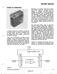
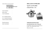
®
Turn to the Expertg
Installation
Guide
This Installation
Guide is intended to be
used in conjunction
Manual.
with the Owner's
The Owner's Manual must first be read
thoroughly prior to installation
Standby generator.
A_ intended
for outdoor
A_ Not intended
applications.
c_0s
LISTED
of the Home
installation
for life support
only.
ELECTRICAL
INTERCONNECTION
DRAWING
®
Turn to the Expertg
\
\
\
N1 N2
GENERATOR
(LOCATED
GROUND
ON THE
/
23 194
I
\
/
\
REAR OF UNIT)
/
\
GENERATOR
OUTPUT CIRCUmT BREAKER
2 POLE
/
\
\EARTH
SPIKE
/
\
"_
\
\
\
\
/
TO HOUSE BRANCH
CiRCUiTS
SPLICED
USING
WiRE
NUTS
EMERGENCY
CiRCUiTS
IllU
40A OR 70A 2-POLE
CIRCUIT
BREAKER
i
BAR
SERVICE
UL LISTED
PANEL BOARD
(8,10,12
OR 16 CIRCUIT
TRANSFER
SWITCH)
CONNECTION
BOX
EXTERNAL CUSTOMER
CONNECTION
TO
EXTERNAL
OF GENERATOR
CONNECTION
PANEL
4 PmN
L
1
=
CONNECTOR
N
0
I
The product contains or emits chemicals known to the state of
California to cause cancer, birth defects or other reproductive
harm.
Study these SAFETY RULES carefully before installing, operating or
servicing this equipment. Becomefamiliar with this Installation Guide and
the Instaflation & Owner'sManualincluded with the unit. The generatorcan
Thank you for purchasing this model of the CARRIERproduct line. This
model is a compact, high performance, air-cooled,engine-driven generator
designed to automatically supply electrical power to operate critical loads
during a utility powerfailure.
Thisunit is factory installedin an all-weather,acousticalmetalenclosure
that is intendedexclusivelyfor outdoorinstallation.This generatorwill
operateusingeitherliquid propanegas(LPG)or naturalgas(NG).
READTHISMANUAL
THOROUGHLY
If youdo not understandanyportionof this manual,contactCARRIER
at
1-877-600-2792.
Throughoutthis publication,and on tags and decals affixed to the
generator,DANGER,
WARNING,
CAUTION
and NOTEblocksare usedto alert
you to special instructionabout a particular operationthat may be
hazardousif performedincorrectly
or carelessly.Observethem carefully.
Theirdefinitionsare asfollows:
Afterthisheading,youcanreadinstructions
that,if notstrictly
compliedwith,will resultin seriouspersonalinjury,severe
propertydamageand/orwithoutlimitation,death.
Afterthisheading,youcanreadinstructions
that,if notstrictly
compliedwith, may resultin seriouspersonalinjuryand/or
severepropertydamage.
Afterthisheading,
youcanreadinstructions
that, if notstrictly
compliedwith,couldresultin damageto equipment
and/or
property.
NOTE:
Afterthisheading,
youcanreadexplanatory
statements
thatrequire
specialemphasis.
Thesesafety warningscannoteliminatethe hazardsthat they indicate.
Commonsenseand strict compliancewith the specialinstructionswhile
performingthe serviceare essentialto preventingaccidents.
Fourcommonlyusedsafetysymbolsaccompany
the DANGER,
WARNING
and
CAUTION
blocks.Thetype of informationeachindicates
follows:
Thissymbolpointsout importantsafety information
that, if not
followed,couldendangerpersonalsafetyand/orpropertyof you
andothers.
,_
Thissymbolpointsout potentialexplosion
hazard.
Thissymbolpointsout potentialfire hazard.
,/_ Thissymbolpointsout potentialelectricalshockhazard.
/_
SAVE
THESE
INSTRUCTIONS
- Themanufacturer
suggests
thatthese
rules for safe operationbe copiedand postednear the unit's
installationsite. Safetyshouldbe stressedto all operatorsand
potentialoperatorsofthisequipment.
The engine exhaust from this product contains chemicals known
to the state of California to cause cancer, birth defects or other
reproductive harm.
operate safely, efficiently and reliably only if it is properly installed,
operated and maintained. Many accidents are caused by failing to follow
simple and fundamental rules or precautions.
CARRIERcannot possibly anticipate everypossiblecircumstance that might
involvea hazard.Thewarnings inthis manual,and ontags anddecals affixed
to the unit are,therefore,not all-inclusive. If you use a procedure,work method
or operating technique not specifically recommended,you must satisfy
yourself that it is safe for you and others. You also must make sure the
procedure,work method or operating technique that you choose does not
renderthe generatorunsafe.
Despitethe safe designof this generator,operatingthis
equipment
imprudently,
neglectingits maintenanceor being
carelesscan cause possibleinjuryor death. Permit only
responsible
andcapablepersons
to operateor maintainthisequipment.
z_
Potentially lethal voltagesare generatedby these machines.
Ensureall stepsare taken to renderthe machinesafe before
attemptingto workonthegenerator.
/_
Parts of the generatorare rotating and/or hot duringoperation.
Exercisecarenearrunninggenerators.
Z_ GENERAL
HAZARD
Z_
Forsafetyreasons,CARRIER
recommends
that the installation,initial start
up and maintenance
of this equipmentis carriedout bya Dealer.
The engine exhaustfumes contain carbon monoxide,which can be
DEADLY.
This dangerousgas, if breathedin sufficientconcentrations,
cancauseunconsciousness
orevendeath.Thisexhaustsystemis factory
installed,in strict compliancewith applicablecodesandstandards.You
must do nothing that might render the system unsafe or in
noncompliance
with suchcodesand standards.
• Keephands,feet,clothing,etc., awayfrom drivebelts,fans,and other
movingor hotparts.Neverremoveanydrivebelt or fan guardwhilethe
unit is operating.
Adequate,unobstructedflow of coolingand ventilatingair is critical to
correctgeneratoroperation.Donot alterthe installationor permiteven
partialblockageof ventilationprovisions,asthis canseriously
affectsafe
operationofthe generator.
ThegeneratorMUSTbe installedoutdoors.
Whenworkingonthis equipment,remainalertat all times.Neverworkon
theequipmentwhenyouarephysicallyor mentallyfatigued.
Inspectthe generatorregularly,and contact your nearest CARRIER
Dealerfor parts needingrepairor replacement.
Beforeperformingany maintenanceon the generator,disconnectits
batterycanes to preventaccidentalstart up. Disconnect
the cablefrom
the batterypostindicatedbya NEGATIVE,
NEGor (-) first. Reconnect
that
cablelast.
Never
use
thegenerator
oranyofitsparts
asastep.
Stepping
ontheunit
canstress
andbreak
parts,
andmayresultindangerous
operating
conditions
fromleaking
exhaust
gases,
fuelleakage,
oilleakage,
etc.
ELECTRICAL
HAZARD
All generatorscoveredby this manualproducedangerouselectrical
voltagesand can causefatal electricalshock.Utility powerdelivers
extremelyhigh and dangerousvoltagesto thetransfer switchas does
the standbygeneratorwhenit is in operation.Avoidcontactwith bare
wires,terminals,connections,
etc.,whiletheunit is running.Ensureall
appropriatecovers,guardsand barriersare in placebeforeoperating
the generator.If youmustworkaroundan operatingunit, standon an
insulated,drysurfaceto reduceshockhazard.
Donot handleany kind of electricaldevicewhile standing in water,
whilebarefoot,or whilehandsor feet arewet.DANGEROUS
ELECTRICAL
SHOCK
MAYRESULT.
The NationalElectricalCode(NEC)requiresthe frame and external
electricallyconductiveparts of the generatorto be connectedto an
approvedearth ground.Localelectricalcodesalso mayrequireproper
groundingof the generatorelectricalsystem.
After the homestandbyelectricalsystemhas beeninstalledit will be
capableof crankingand startingat anytime whilein the "Auto" mode.
Whenthe unit starts in "Auto"the load circuits are transferredto the
STANDBY
(generator)
powersource.
Topreventpossibleinjurywhenworking
on the systemalwaysset the generator's
Auto/Off/Manual
switchto its
"OFF",remove
controlpanelfusesanddisconnect
the startingbattery.
In caseof accidentcausedbyelectricshock,immediatelyshut downthe
sourceof electricalpower.If this is not possible,attemptto freethe
victimfromtheliveconductor.
AVOID
DIRECT
CONTACT
WITHTHEVICTIM.
Usea non-conducting
implement,such as a ropeor board,to freethe
victimfromtheliveconductor.
If thevictim is unconscious,
applyfirst aid
andgetimmediatemedicalhelp.
Never wear jewelry when working on this equipment.Jewelrycan
conductelectricityresulting in electric shock,or may get caught in
movingcomponents
causinginjury.
A FIREHAZARDS
A
Forfire safety,the generatormustbe installed
and maintainedproperly.
Installation
alwaysmustcomplywith applicablecodes,standards,laws
andregulations.
Adherestrictlyto localstateand nationalelectricaland
building codes.Complywith regulationsthe OccupationalSafetyand
Health Administration(OSHA)has established.Also, ensurethat the
generatorisinstalled
in accordance
with the manufacturer's
instructions
and recommendations.
Followingproperinstallation,
do nothingthat
might altera safeinstallation
and rendertheunitin noncompliance
with
theaforementioned
codes,standards,lawsand regulations.
Keepa fire extinguishernearthe generatorat all times. Extinguishers
rated"ABC"bythe NationalFireProtectionAssociationareappropriate
for useon the standbyelectricsystem.Keepthe extinguisherproperly
chargedand befamiliar with its use.If youhaveanyquestionpertaining
to fire extinguishers,
consultyourlocalfire department.
/_ EXPLOSION
HAZARDS/_
Do not smokearoundthe generator.Wipe up any fuel or oil spills
immediately.
Ensurethat no combustible materialsare left in the
generatorcompartment,or on or near the generator,as FIRE or
EXPLOSION
mayresult.Keepthe areasurroundingthe generatorclean
andfreefrom debris.
Gaseousfluids such as natural gas and liquid propane(LP) gas are
extremelyEXPLOSIVE.
Install the fuel supply system accordingto
applicablefuel-gas codes.Beforeplacing the homestandbyelectric
systemintoservice,fuel systemlines mustbeproperlypurgedand leak
testedaccordingto applicablecode.Afterinstallation,youmustinspect
the fuel systemperiodicallyfor leaks.Noleakageis permitted.
It will be necessaryto paya visit to your local municipaloffices
to applyfor a building permit. Building permitsare necessaryto
ensure proper installation, safety and adherenceto all local
building code specifications.The location and phone number
can befoundin the governmentsectionof yourlocal phonebook.
Plan the location of your generator.NOTE:Do not place the
generatordirectlyunder a window.Selectan area outside of
your homenearestyour incominggas service.
Arrange for installation of rigid gas piping (per local code
specifications)to the locationwhereyou intendto positionyour
generator.Fuel piping should includea fuel shut-off valve.The
termination of the rigid piping should be aligned with the
generatorfuel inlet locatedat the rear of the compartment.
Clearan area5-1/2feetby5 feet minimumofgrassandvegetation
to a depthof 5 inches.This includesthe distancethe generator
shouldbeset awayfrom anystructure(3 feet)and 6 inchesbeyond
thewidthand lengthof thegeneratormountingpad(48"L x24"W).
NOTE:Local codes may supercede these requirements.
.
Layblack poly-filmto coverthe area.
6.
Fill the areato groundlevelwith peagravelor crushedstone.
7.
Placethe generator,which is attached to the mounting pad,on
the area youhavejust prepared.
8a,
Drivean 8 ft. groundingrod into the groundto grade.
8b. Attach one end of the grounding strap (No. 12 AWGstranded
copperwire)to groundingrod andthe otherend to thegrounding
lug (locatedat rear cornerof unit). Makesuregroundingrod and
strap are not exposedabovegroundlevel. (NEDcodeappliesto
groundingmethod.)
NOTE:Generatormodeswitch should be placedin the "off"
position.Generator main line circuit breaker should be
switchedto "off" or openposition.
9a,
Make the connectionbetween the rigid fuel piping and the
generatorusing the suppliedthreadedflexiblefuel line. Theflex
hoseshouldbestraight. Donot bendthe hosein place of using
pipe elbows. Use a pipe sealant suitable for gaseous fuel
connections.Checkconnectionsfor leaks by opening manual
fuel shut-off valve and swab or spray connectionswith soapy
water. If a leakexists the areawill bubblewith the presenceof
the soapywater.
9b. If a leak is located,shut off fuel, and disconnectflexible piping.
Drythe threadedendsand reapplyan adequateamount of pipe
sealant. Reconnectflexible fuel line, open fuel supply and
recheckfor leaks.If leak still exists,repeatstep 9b.
lOa. Determinewherethe flexible conduit will pass through the housefrom inside to outside.
Whenyouare certainyouhaveclearanceon eachsideand within the wall, drill a small pilot
holethrough the wall to markthe location.
ID
Theouterdiameterof thethreadedendis 15/16".
lOb. Using a hole saw,drill a 1-3/4 inch diameterhole in the house'swall to allow the conduit
to fit through.
lla.
Fromthe inside of the house,feed the end of the 30-foot conduit (which is pre-wiredfrom
transfer switch) throughthe wall to outside.
llb.
Removethe threadedlock nut from the conduit coupling.
llc.
Lift cover.Removeinternal coverplatescrewand internalcover. []
Removethe knockout in the lower right cornerof the external
connectionbox.Fromthe rear of the connectionbox,feed wires
& 4 pin plug into box.Slip the lock nut overwires and plug and
tighten securely onto conduit coupling. Using appropriate Ground
fasteners,mountexternalconnectionboxoverpre-drilledholeto Screw
fully conceal the hole. Seal around the hole and conduit with
silicone caulk from both the inside and outside of the home.
Knockout
Also, caulk around the sides and top of the boxto seal the edgesto the siding or wall.
Connectwires to lugs; Black to black, white to white, and red to red. Torquenuts to 20
inilbs. Snaptogetherthe 4-pin plug connector.Loosennut from groundinglugand attach
groundwire (green)from conduit. Reinstallnut and tighten to 45 in/lbs.Reinstall internal
coverplate and screw.Closecoverand installlock.This wiring iscomplete.
The externalconnectionboxmust be lockedto
ensuresafety and to discouragetampering.
12. Locateautomatic transfer switch with built-in emergencyload center within one foot of
main distribution panel. The automatic
transfer switch with built-in load centercan
be located to the left or right of main
distribution panel. Hold transfer switch
against the mounting surface. Level the
transfer switch and mark the mounting
holes.Drill the appropriatesize pilot holes.
Mountautomatictransfer switchwith builtin load center to mounting surface with
appropriatefasteners.
13a. Removethe main electrical distribution panel cover. Remove
appropriatesizeknockoutfrom the bottomor sideofthe mainpanel.
(A 2-footflexibleconduit is pre-wiredfrom the transferswitch with
built-in load center.) Removethreaded lock nut from conduit
coupling. Feedall wiresthroughknockoutintomainpanel.Slip lock
nutoverwiresandtightensecurelyonconduitcoupling. Removethe
black (hot) wire from a circuit breakerthat protectsa circuit you
want to havepoweredin the eventof a powerfailure.- continuedon
page8
- continuedfrompage7
Wire nut the black wire to the matching
circuit lead wire from the emergency
circuit breakerfrom load center in the
transferswitch.(Allcircuit wiresare color
coded and
labeled for easy
identification). UL approved wire
Iocknutsare includedin installation
kit.
WARNING
If theutilitypowersupplyisnot turnedoff, sparkingcan
occurat thebatterypostsandcausean explosion.
NOTE:
Dielectricgreaseshouldbe usedon batterypoststo aid in
the prevention
of corrosion.
NOTE:In areas where temperaturesregularlyfall below10° F
(-12° O) it is recommended
that a pad type batteryheater be
installedto aid in coldclimatestarting.
Tracethe black (hot)wireyou havejust
connectedbackto the sameRomexcable(circuit)to find itsmating
white(neutral)wire.Wirenutthis wireto the matchingcircuitnumber
on the white (neutral)wire comingfrom the emergencyload center.
Repeatthis processwith remainingcircuits to be poweredby the
generator.
NOTE:
Bothgroundedandungrounded
conductors
for eachcircuit
mustbe reconnectedto the emergencyloadcenterwiringusing
thesuppliedwire Iocknuts.
Thechart belowshowsthe circuits providedin the loadcenter.
'llm[']L
l_,J
l,_v
1
1
1
1
3
5
3
,.i,_vl
1
1
i_,_rlvl i['_iv
1
1
3
1
5
1
5
5
5
5
NOTE:Circuitsto be movedmust be protectedby same size
breaker.Forexample,a 15 Ampcircuitin mainpanelmustbea 15
Ampcircuitin transferswitch.
13b.Installthe40 Ampor 70 Ampdoublepole
circuit breakerthat you have purchased
(Seedetailon page6) intomainelectrical
distribution panel. This circuit breaker
must be compatiblewith your main
electricaldistributionpanel. It may be
necessaryto repositionremainingcircuit
breakersor removecircuit breakersthat
havebeendisconnectedto accommodate
the insertionof the 40 Amp
or 70Ampdoublepolecircuitbreaker.Connectwhite wireto the main
distributionpanelneutral bar.Connectgreenwireto main electrical
panelgroundbar.Connectthe black and red wiresto the 40 Ampor
70 Ampdoublepolecircuit breaker.
14. Recommended
batteryis automotivetype
Group 26 12V negative ground with
minimum350 CCAat 0° F (7 kW)or a
minimum525 CgAat 0° F(10 kW,13 kW
and 16 kW).The hold down clamp is
included. Connect positive (+) (red)
cable to positive (+) battery post.
Connect negative (-) (black) ground
cableto negative(-) batterypost.
WARNING
Setthegenerator'sAUTO
/ OFF/ MANUAL
switchto"OFF."
Turnoff utilitypowersupplyto thetransferswitch.If the AUTO/
OFF! MANUAL
switchisnotsetto its"OFF"position,thegenerator
cancrankand startas soonas the batterycablesare connected.
Part# 0G0598REV.*
15. Switchservicemaincircuit breakerto "on" or closedposition.Switch
the circuit breakersin theemergencydistributionpanelto the "on" or
closedposition.Switchthe generatormainline circuit breakerto the
"on" orclosedposition.Verifythat the40 Ampor70 Ampdoublepole
circuit breakerthat was insertedin the main electricaldistribution
panelis switchedto the "on"or closedposition.Placegeneratormode
switch in the "AUTO"position.Verifythat fuel valve on rigid gas
piping is open. Perform stepsin Sections2.1 through2.5 of the
Installation
& Owner'sManualpriorto testingthesystem.
16. Switchservicemain circuit breakerto "off" or open position.This
simulatesthe loss of utility power.Thegeneratorshould crankand
start within 20 seconds. Load transfer should occur within 10
secondsof generatorstart. To return systemto automatic mode,
switchservicemain breakerto "on" or closedposition.Thissimulates
the returnof powerfrom the utility. Thegeneratorwill runfor a short
cooldownperiodof severalminuteswhilethe entire systemstands
readyfor the nextpoweroutage.
NOTE:Whenutilityvoltagesourceis lostbythe generator,the
systemset lightwillflashrapidly.
17. A switch on the control
panel allows you to select
the day and time for the
systemto exercise.Toselect
a time and dayof the week
you must perform the
ExerciserSwitch
following sequenceat that time. Verifythat the Auto/Off/Manual
switchis setto "AUTO'.'
Holddownthe "Set Exercise]]me" switch until the generatorstarts
(approximately10 seconds)and release.Thegeneratorwill start and
runfor approximatelytwelveminutesandthen shut downon its own.
Thegeneratoris nowsetto exerciseonthat dayandat that time every
week. If the batteryis disconnectedfor anyreasonthe exercisetime
mustbe reset.NOTE:Untilthe exerciseris set, all thered LED'swill
flashin theAutoor Manualmode.
YourCARRIER
HomeStandby
generatoris nowready!
CATALOG
NO.ASPB07-1SI
Turn to the Experts:
PRINTED
INTHEUSA5.00