1
Compressors and Condensing Units
© Open, Water-Cooled
COMPRESSOR AND CONDENSING UNIT PHYSICAL DATA
*Also used for low pressure oil line
connection.
| This bank of cylinders on 5F30 only.
5 x
*Also used for low pressure oil line @)
connection.
| This bank of cylinders on 5F60 only.
*This bank of cylinders on 5H60 and
66 only.
*Also used for low pressure oil line
connection on 5H120 and 126.
H5H80 and 86 only.
+These banks of cylinders on 5H120
and 126 only.
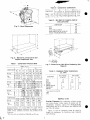
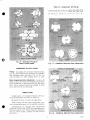
Fig. 4 - 5H80, 86, 8-Cyl and 5H120, 126, 12-Cyl Compressors
COMPRESSOR KEY
Gage connection 1/4-inch IPS.
Dual pressurestat.
Qil level sight glass
Discharge shut-off valve. (See Physical Data for size.) Oil pump rotation arrows
Suction shut-off valve. (See Physical Data for size.) Suction valve, manifold or manifold cover. Remove for access
og to suction strainer.
Oil filler plug
Crankcase drain (5/8-inch -18 plug on all 5F compressors, Oil pressure connection 1/4-inch IPS (high pressure).
shut-off valve on all 5H compressors) Capacity control adjustment.
Oil Filter
Crankcase heater casing
DO OHOOOO
OJD 900:
Oil pressure regulator Oil pressure connection 1/4-inch IPS (low pressure).
© Carrier Corporation 1968 5F,H-1SI
Fig. 6 - Belt Drive, Direct Drive and
Duplex Compressor Unit
Table 1 - Compressor Physical Data
BARE (Fig. 5)
5F 5H
COMPRESSOR 40,160, | 80, | 120,
20 40 | 60 | 461 66 | 86 | 126
WT (Ib) 175 215 | 355 | 400 | 610 | 795 | 1115] 1580
DIM Al 1-37] 1 1- 9%) 1-11%1 2-64) 2- 7%| 3-7%41 3-11
(ft B| 1-6 | 1 1-7 11-9 | 2-07] 2- 371 2-0%| 2- 3%
и С| 1-6%| 1-6 | 1- 8%] 2- 0%] 2-5 | 2- 5% 2-8 | 2-107
BELT DRIVE* (Fig 6)
WT (Ib) 260 1200] 515 | 600 | 915 14085] 1650] 2215
DIM Al 3-2 133:13- 9%) 3- 94) 4-8E2-TA1 5-04| 5 7%
(ft-in.) B| 1-9% 39%) 2 27| 2- 2%] 2-831 2:36 | 3-9%| 3-11%
Cl 2-5 EZ4%|2- 1%| 2- 6% 3-14F3=231 3-6%| 3- 4%
DIRECT DRIVE (Fig 6)
WT (Ib) - 4801 565 | 880 | 1065 3730) 2210
DIM A — 3% 4- 0%] 4-9%] 4-100, E8871 6- 77,
(froin) B| -— 924 1- 971 2:0] 2- BLEEP 2 7%
cn cl - 334] 2- 6%| 3-14] 3- 341 SPA 3- 9%
BE 5H DUPLEX (Fig. 6)
COMPRESSORE———— ——
40/60 | 60/80 | 80/80 | 80/120 | 120/120
WT (Ib) | 2210 2713 3225 3840 4305
DIM AL 8-7, 9-2, 10-10% | 11-5% 11-10%
(fin) Bi 2-85, 2-85, 2- 85, 2-85, 2- 85,
ne Cl 3-44 | 3-64, 3- 6%, 3-9% 3- 9%
nm EEE
x=) Compressor units (except 5H80) with slightly different
dimensions and horsepower requirements are available to accom-
modate oversize condensers and motors See certified prints for
dimensions.
*Belt drive units not available for 5H46, 66,86 and 126 sizes
st
ed a.
Table 2 - Compressor Connections
rp о Hr aE rh AA EAT RAR SO Te
se | sH
20 30] 40 60 | 40,46] 60,66] 80,86 | 120,126
1-1/81 1-5/8 2-1/8] 2-5/8] 3-1/8] 3-5/8
4-1/8
7/81 1-3/8 1-5/8|2-1/8 2-5/8|3-1/8 | 3-5/8
COMPRESSOR
CONN. Suct
(in. OD) Disch
pOr
Table 3 - Min Rpm for Capacity Control
and Lubrication
COMPRESSOR RPM
5520 600
5F30 700
5F40; 5H40,46; 5H40/60 800
5F60; 5H60,66,120,126; 5H120/120 900
5H80,86; 5H60/80,80/80,80/120 1100
J ad
AY
y -ÂÀ
Ss
N
—, | SPACE FOR
23] ТУВЕ ВЕМОМА!.
EITHER END
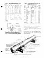
Fig. 7- Direct Drive, Belt Drive Condensing Unit
(Table 5)
Table 4 - Condenser Water Connections
(in. FPT)
CT MAX. IN PA
CONDENSER __ MAX PASSES | _ MIN PASSES
In and Out In* Qut
se | IA 1/2 1
5530 3/4 3/4 1j
5F 40,60 1-1/4 1-1/4 1-1/2
09RH027 2 2 2-1/2
O9RH043,054,070 2 2 3
O9RH084,097 2-1/2} 2-1/2} 41
O9RH127 37 31 5!
“Two connections required.
TMPT
HPS
INSPECT SITE
Provide Cledrance for removing cylinder heads
and valve plates. Allow space on pump end for
crankshaft removal. Space for 5F20,30,40,60,
5H40,46,60 and 66 is 20 inches; for 5H80,86,120
and 126, 30 inches.
Space at end of condenser must be equal to
length of condenser to facilitate tube removal
and cleaning.
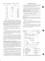
Table 5 - Condensing Unit Physical Data (Fig. 7)
*Special order only.
tTFor 60- and 75-hp motors.
AUDE A me TN de SAO LEGION
DRIVE ~~ BELT В
COMPR 5F20 | “5F30 5F40 | 5660 | 5H4O I 5H60
coo | 0 | 30 | 20 | зо | 40* | 30 | 40 | 60 | 40 | во | в 0271 043 | 027 | 043
WT (Ib) | 385 | 425 | 430 | 460 | 830 | 790 | 960 1050 | 1070 | 1230 | 1500 | 1715 | 1955 | 1925 | 2165
0 A|3- 2%| 3-4% | 3-2% | 3- 4% 5-3 | 4-3% | 5-3 | 6-2 | 5-3 | 6-2 | 6-2 | 6-5 | 6-7%| 6-5 | 6-74,
РМ. ов 1- 9% 1-9% 2- 3 2-3 2- 3, 2-8% 210%
in) Ch 2.5 2-4% | 2- 9% 2-10% 3-1% | 3-8%| 3-94] 3-11%4| 3-10% | 4-0%
DRIVE “| 7 Ш ВЕСТ a DIRECT |
COMPR 5H60 | ВЕ 5H80 | 5H120 i sr | -
COND | 654 | 0541 1970 : 043 | 054 0701 084 : 07 054 © 070 084; 097 | 40 | 60 | -
WT (Ib) | 2390 | 2650 | 2710 2845 2990 | 3050 | 3385 | 3690 | 3589 | 3664 Е 955 | 3240 | 880 | 970 | - _
DIM Al 7-11% 7-11% | 6- 7%, 7-11% | 8-3% |10- 3% 7-11% | 8-37 |10- 34, 5-3 | 6- 2 Ш
(fin) 3 2-10% 3- 8% 39% | 3-11% 1- 9% _
Cl4-0%| 4-34 45% | 4- 8, 210% | -
DRIVE | | DIRECT Во
COMPR 5F60 5H40 | SHAG | _5H60 | 5H66
COND | 60 027 i027 cé | 043 “054 | 070 08 | 054 070! 08% | 054 | O70 0847 097
WT (Ib) 1060 | 1385 65 | 1890 | 1890 Es | 2095 | 2025 | 2190 | 2740 | 2800 | 2190 | 2740 | 2800 ue
om Al6-2 [6-5 16-5 | 6-7% 6 7ul 7-4 6- 7% 7-11% 8_3% 7-11% | 8- 3% 10-3%
(froin) B|1= 9% 2-0% 2-2 | 2- 2 2- 4% 2- 4% 2-7% 2- 45 2-7
С | 3- 2% | 3-4% | 3-95 | 3-11% -1% | 4- 04; 4- 0% 4-3 4- 0% 4- 3%; 4-4%
DRIVE — o o a DIRECT N В
COMPR 5H80 ! 5H86 | 5H120 | 5H126 | —
COND 1054 | 070 1084 | 097 | 070 | 084 097 | 327 070 084 | 097 1 997 1 0997 |: 197 —
WT (1b) | 2930 | 2990 | 3315 | 3620 | 2990 | 3315 | 3620 | 4230 | 3570 | 3870 | 4130 | 4740 | 4130 | 4740 | -
om Al 7-11% (83% 10- 34| 7-11%| 8- > 10-3% | 8- 4% 7- Пу 8-3% | 10-3% | 8- 4% 10- 3 8- 4% |
min) B| 26% 2-9% 26%) 27M | 10% 2-5, 27% 2-104 | 2-74 2-10% | -
С 4-5% 45 5% | 4-3% | 4-6% | 4-10% 4- 8% 4-8 5-04 4- 8% 50% | —
| |5F Condenser No. "77771 09RH Condenser No.
Table 6 - Condensing Unit Refrigerant Connections (in. OD)
| | _ г .
“COMPR 5F20 | 5F30 | 5F40 | 560 | 5H —-
COND 20 | 30 | 20 | 30 | 40 | 30 | 40 | 60 | 40 | 60 | 027 60 | 027 43 -—
Suction 1% 1% 1% 2% 2% _
CON Liquid Y 5 | % {| % | % | %| % | 1% | % | M -
COMPR 5H46 | en SHE | 5H66 | 5H80
COND | —: 58 | 054 | 070 | 077 | 043 | 0st : 0s | 070 | 084 | ost : 070 084 0% | 043 | 05
Suction 2% 3, 3% 3%
CONN Liquid | vp | M % | 1% | 2% 1% 1%. | 1% | 1%
COMPR 5H80 5H86 | 5H120 | _5H126 | -
COND — : 0701 084 | 097 | 070 | 084 | 097 :- 327 * 054 | 070 | 084 | 097 | 127 997 ! 397 | -
Suction 3% 3% 4% 4% —
CONN. | Liquid | 1% | 2% м | 2% | % | 2% 2% -
| J SF Condenser No.
5] 09RH Condenser No.
*For 60- and 75-hp motors.
Machine Room Temperature and Ventilation -
Locate compressor or condensing unit in well
ventilated space. Check code requirements. Pro-
vide forced ventilation thru ductwork when natural
ventilation is inadequate.
Protect water-cooled condensers, water lines,
and accessories from freezing during winter
shutdown periods.
PREPARE FOUNDATION
Fasten compressor to: (a) steel base and vibra-
tion isolators onfloor; (b) steel base and condenser
support stand or (c) concrete base,
Floor Foundations - Locate compressors over
joists or beams wherever possible.
Weak floors in old buildings must be reinforced
with steel beams or timbers to support the heavy
compressors or condensing units, Use care in
placing supports to avoid transmitting objection-
able vibrations to other areas.
Concrete Foundations one to two times the weight
of the machinery they support will absorb vibra-
tion. See Fig. 8 and Tables 7 and 8 for recom-
mended dimensions. Let foundation set sufficiently
before compressor is installed (approximately 3
days). Allow for 3/8 inch to 1/2 inch grout after
compressor is installed.
Heavy aggregate concrete weighs about 150
pounds per cubic foot.
INSPECT UNIT
Inspect shipment for damage or loss. File
claim immediately with shipping company for any
loss or damage.
¢ OF MOTOR
+
¢ OF MOTOR В ,
BASE
¢ FLYWHEEL
7 DIAM BOLTS
Move and rig unit carefully to prevent damage
to gages, mounting brackets, refrigerant piping
and connections.
COMPRESSOR INSTALLATION
Compressor on Steel Base and Vibration Isolators
on Floor — Install vibration isolators on one end of
unit at a time. See Fig. 9 for typical vibration
isolator mounting.
Motor fastening set supplied with all com-
pressors (except 5F20,30) includes several beveled
washers. Washers are installed under heads of
capscrews used to fasten unit base to vibration
isolators or floor.
Position compressor and motor on frame and
check height of vibration isolators. Shim between
vibration isolators and floor to level compressor
base Secure vibration isolators to floor. If beveled
washer (Fig. 9) is omitted, end of capscrew may
strike the floor and cause vibration isolator to
rupture when it is secured to floor.
Condenser and Stand Assembly - Place cast iron
condenser stands in their correct location, Make
distance ''C'' (Fig. 10) between tapped holes on
top of stand equal to holes in lower flange of com-
pressor unit base. See Table 9 for dimensions.
Shipping caps are soldered to the 5F20,30,40
and 60 condensers at the factory. To remove caps
turn condensers upside down. This prevents solder
from falling into condensers.
Bolt lower support strap loosely to lower side
of each condenser stand.
Place condenser on stands with front water
head at compressor end of base. Position con-
Z DEPRESSION FOR COMPRESSOR
BOTTOM PLATE 5F30 ONLY
¢ COMPRESSOR
CORNER BOLTS (2)
(5F40, 60, 5HI20 ONLY)
L DIAM
4 REQD
¢ FLYWHEEL
BELT GUARD
¢ COMPRESSOR
SEE TABLE 7 FOR DIMENSIONS
*Dimensions apply to motor mounting
bases or rails. Obtain from motor
manufacturer.
{Calculate dimension by consulting mo-
tor and pulley catalogs.
(4) REQD 5F20 8 30 ONLY +5H120, 1 in.
Fig. 8 - Concrete Foundation Details - Sizes SF 20,30,40,60; 5H40,60,80,120
569
Table 7 - Concrete Base Dimensions (Fig. 8)
DIMEN CF 5H
(in) | 20 | 30 40 | 60 | 40 | 60 80 | 120
A 36 48 53 | 57 | 60 | 71
B 19 26 28 | 30 | 40 | 37
c | 7 | 9 10 13 | 1415 | 16
D 33-1/8 45 - | - | - | 66
Е 20.2* 25.5* 30.7% 38.2*
19.31 26.61 32.21 36.71
F 8 9 | 14-1/2
G 5 4 | 5112 5-1/2
H 2.7/8 | 6 6:23/32|7-3/4 (8-1/2 14-172
J 15-1/32|6-15/16 9-1/2|10-1/2 11-1/2| 12 1612/1817
Ck [eens | M 1-1 - 10
L 1/2 5/8
M ЗО 4 —6
N 1-1/2 1-3/4 |212| 2
P à 2-1/4 2-1/2
q - A | | 66
R - 1-3/4) 2 - - | - | 134
—*1450 rpm. a В
11750 rpm.
UNIT BASE
sere
PLATE WASHER
BEVEL WASHER
VIBRATION
ISOLATOR
MOUNTING
BOLT HOLE
SHIMS WHERE
NEEDED
Fig. 9 - Typical Vibration Isolator Mounting
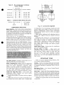
HOT GAS INLET
NAMEPLATE
UPPER STRAP
FABRICA STRIP
2 IPS VENT PLUG el ae
EA
WATER CONN. INLETS FOR 4-PASS
(5F40,60); 3-PASS ON O9RH
BOTTOM FOR INLET, TOP FOR
OUTLET FOR 8-PASS (5F40, 60); &
6-PASS ON O9RH a
WATER CONN h\ ie
OUTLET AN
FOR 4-PASS S
(5F40,60) 3-PASS dd
O9RH. PLUG FOR
6-PASS AND 8-PASS
A De
E
>
CS
*5F20 AND 30 HAVE FRANGIBLE DISC
Table 8 - Distance Between Compressor and
F Iywheel Centerlines (Fig. 8)
COMPR| MOTOR | COMPRESSOR| BELTS | DIMEN X
SIZE HP RPM (No) Size | (in.)
5F20 | 5,7-1/2,10 1750 & 1450 (2) B | 7-15/16
5 1450
E 1750 (2) B | 921/32
7-1/2 1450
10,15 1750 & 450 | (9 В 1031/32
5F40 | 7-1/2,10,15,20 175081450 | (3) B | 10-3/4
seen | 10.15.20 1750 & 1450 | (3) В | 11-7/16
10,15:20,25 | 175081450 | (4) B | 1113/16
sua) | 20,25,30,40,50 1750 & 1450 | (3) C | 13-3/8
30,40, 50 1450 (5) C | 13-3/4
30 1750 & 1450 (3) С 14-18
sep | 30 1450 (5) C 14-12
40,50 1750 & 1450 | (5) C 14172
60,75 1750 (5) C | 14-172
40,50 1750 (5) C 20.12
40,50 1450 (6) C | 18-5/8
sep | 60 1750 & 1450 | (6) C | 18-5/8
75 1750 (6) C 18-5/8
60,75 1450 (9) C 21-3/8
100 — | 1750 (9) C |21-3/8
60 1750 (9) C |20-5/8
5H120 | 60 1450 (9) C | 21-12
75,100 1750 & 1450 | (9) C |21-12 |
denser so hot gas inlet is on top and ends over-
hang stands same distance on each end.
Assemble upper straps loosely around the
condenser.
Compressor on Steel Base and Support Stand -
Place compressor unit on top of condenser stands
and bolt into place with capscrews and lock
washers provided.
AN TAPPED MOUNTING
A HOLE
о
С
Seale ee
RELIEF VALVE 385 PSIG ON
5F40,60 AND ALL O9RH ¥
WATER PRESSURE REGULATOR CONN
LIQUID SHUT-OFF VALVE
TAPPED MOUNTING HOLE
Cie LOWER STRAP (MOUNTED TO UNDER
SIDE OF CONDENSER STAND)
Fig. 10 - Typical Assembled Condenser Package
Table 9 - Dimension ''C"! (ft-in.) (Fig. 10)
DRIVE
COMPR Belt Direct В
20 2--8-3/8 _
30 2—8-3/8 —
SF 40 3—7-7/8 3—7-7/8
60 3—7-7/8 3-7-7/8
60* - _ 4-2-3/4
40 4-2-3/4 4-2-3/4
46 _ 4—2-3/4
60 4-2-3/4 4—2-3/4
66 — 4-2-3/4
60* — 4—5-1/2
oH 66* — 4—5-1/2
80 4—7-3/4 5—9-3/4
86 — 5—9-3/4
120 4-7-3/4 5—9-3/4
126 — 5-9-3/4 oo
*Oversize base.
Loosely connect compressor discharge line
and adjust condenser position so discharge line
is inline with condenser inlet. Assemble discharge
lines for 5H Series compressors as shown on
special diagram sheet included in 5H condenser
piping packages, Before making joints, try coup-
ling or belt guard to ensure piping clearance,
Place strips of Fabrica provided between lower
support straps and condenser, See Fig, 10.
Tighten lower strap enough to lift condenser
off stands.
Sweat discharge line to condenser, Adjust con-
denser position as required to prevent distortion
of discharge line. Instructions are included inthe
piping assembly package,
Place Fabrica strips (see Fig. 10), between
condenser and upper straps. Tighten strap bolts
to secure condenser to stand, NOTE: Use lower
straps only for SF20 and 30 units. Place the two
extra strips of Fabrica between top of condenser
and base. Assemble discharge line as described
above.
Compressor Bolted to Concrete Base - See Fig, 8.
set compressor level on foundation bolts, (Level
in two directions.) Removal of discharge shut-off
valve exposes face of mounting flange on com-
pressor which can be used as a leveling pad, Lo-
cate and level motor slide rails, Provide for 3/8
inch to 1/2 inch grout. Tighten foundation bolts
handtight. Do not use wrench.
Wet top of concrete, pour grout and tamp to
fill all spaces between machinery and concrete.
Allow grout to dry slightly then trowel smooth,
Suggested mixture for grout is one part Port-
land cement to two or three parts of sharp sand.
Tighten foundation bolts moderately tight when
grout has hardened for 24 to 36 hours, Overtight-
ening bolts may cause compressor misalignment,
at
CRANKCASE HEATER
Energizing crankcase heater helps prevent oil
and refrigerant from mixing and accumulating in
crankcase when compressor is off.
Wire heater to relay or set of normally closed
contacts in compressor starter so it will be de-
energized when compressor is operating.
Installation of Heaters - Remove rubber plug from
crankcase heater casing (see Fig. 1 thru 4).
Insert heater element entirely into casing.
Element should fit snugly, not loosely.
Wire in accordance with local codes and dia-
gram (Fig. 11).
Relay Coil voltage is determined by control cir-
cuit voltage which must be specified when ordering
relays.
Mount relays vertically.
When crankcase heater is installed, system can
operate on a single pumpout cycle as shown in
schematic, Fig, 11.
Crankcase heater packages are given in Table
10 and corresponding relay is in Table 11. When
two heaters are usedona SH80 or 120 compressor
only one relay is required.
OD —— Oro BoB)
Lh AEC m mmm me rm RY
AFCO === == EY
; bem CTT ToT TTT 11 COMPR
a || | MOTOR
: o ||
RAMPS LPS OL OL SAFETY @ 1!
GE pers O |
NR 4 : |
4 = т ео = ALAN wr wa rw me we "+ = = | |
гонт an +!
| 1 pest SAFETY PS |
RESISTOR A ||
| Tann — —
| Ш = HEATER © A ja
PL An
| Mi PS T1
(7512)
| SEE NOTE SZ ОИ
ré
|
В ON-OFF_ TO Lg ON
DE FAN MOTOR
e
=1 COMPONENTS FOR CRANKCASE HEATER INSTALLATION
NOTE: Auto-suction stop valve (flooded systems only)
C — Compressor
CH — Crankcase Heater
HPS — High Pressure Switch
LLS — Liquid Line Solenoid
LPS — Low Pressure Switch
OL — Overload
PS — Pressure Switch
R — Relay
T — Thermostat
Terminal Connections,
Marked
Component Connection,
Unmarked
Component Connection,
Marked
---- Field Wiring
Fig. 11 - Wiring Schematic Single Pumpout Cycle
Table 10 - 5F,H Compressor Crankcase
Heater Package
ELECTRICAL
COMPRESSOR | CHARACTERISTICS | PACKAGE NUMBERS
Volts Watts
115 100 -5-F-—20---381
5F20,30,40,60 230 100 5-F-_20---391
115 200 -5-H-—40--—381
5H40,46,60,66 230 200 -5-H_—40———391
115 200 -5-J-—40-——291
>H80,86,120,126 1 20 200 5-J--40-—-291
Table 11 - Crankcase Heater Relay (60- Cycle)
CONTROL CIRCUIT VOLTAGE PART NUMBER |
115 HN6TAJ-101
208/230 HN61AJ-T08
COMPRESSOR OPERATION
Motor Rotation - Start motor before connecting to
compressor. Rotation direction must be same as
arrow cast on pump cover or plate attached near
pump end bearing housing. To rotate compressor
in opposite direction the manually reversible oil
pump must be reversed as follows:
5H120 AND 126; ALL 5F COMPRESSORS - Remove
6 capscrews from oil pump cover. Do not damage
gasket. Rotate cover 180° and replace. Arrow will
now be on top and show new direction of rotation.
5H40,46,60,66,80 AND 86 COMPRESSORS - Drain
oil below level of end bell cover. Remove end bell
assembly and pump end cover, Rotate cover 180°
and replace. Reverse direction of external arrow
(shows compressor rotation without removing end
bell). Arrow on pump end cover must matcharrow
on main bearing housing. Replace end bell and
refill with Specified € oil.
aT Te C2
Var a FU 418 NE NP 4 AU LT NC 4 NE A LE UN AE UN CAES M1 AN NA UNE SE A NEA 2 EP EE NE 2 0 2 A a te a te a a a a a eT
FERN 1 ENEE: pts
X A a a E a WO a | m о ня я = А Ta
A > e e a т E A TELE
ue Te: a ho
Ce
on ne Be YN
Qil Safety Switch installation instructions are in-
cluded in Oil Safety Switch Packages.
Motor Fastening Set supplied with all compressor
units (except SF20,30) includes motor blocks and
shims for motor alignment; capscrews, plate
washers and lock washers for fastening motor to
base; taper dowel pins for securing motor position
on base (after alignment); beveled washers for
fastening unit base to vibration isolators or floor.
Install and Align Belt Drive — Clean motor and
compressor shafts, flywheel and motor pulley
bores with fine emery cloth.
Install motor pulley, flywheel and keys tightly
on shafts.
Slide motor forward on rails to install belt. Line
up flywheel and motor pulley with a straight edge
MISALIGNMENT
SHAFTS MUST
BE PARALLEL
STRAIGHT EDGE
Fig. 12 - Correct Belt Alignment
or string (Fig. 12) or by placing a round rod in belt
grooves. Slide motor pulley on shaft to correct any
parallel misalignment. Loosen motor hold-down
bolts and turn motor frame to correct any angular
misalignment.
Move motor backward with adjusting bolts to
tighten belts. Tighten belts just enough to prevent
slippage.
Determine belt tension by" (a) loosening belts
until they slip when motor starts (belt squeals),
then tighten enough to eliminate slippage, (b)
amount belt 1s depressed at center of span (heavier
belts deflect approximately 1 inch for a 24-inch
span; lighter belts or longer span deflect propor-
tionately more)
Install Direct Drive — Instructions for installation
are in the coupling package
Securing Motor to Base — Align motor and
compressor. Drill and ream two holes thru motor
feet and base. Secure motor to base with two
#6 x 2-1/2 taper dowel pins provided in motor
fastening set. Locate holes diagonally opposite
motor feet. Use 9/32-inch diameter drill and #6
taper reamer.
REFRIGERANT PIPING
Refer to Carrier System Design Manual, Part
3 for proper piping techniques.
Venting - Replace vent plugs (front and rear heads)
and drain plug (front head) withnipples and valves
if frequent draining of condenser (water side) is
desired.
Refrigerant Drier - See System Design Manual,
Part 3, Page No. 3-75.
Felt Filter - Install felt filter (supplied with com-
pressor) in suction line screen. Remove after 50
hours of compressor operation. If dirty, clean with
kerosene or neutral spirits and replace for another
50 hours operation. If filter is clean, leave it out.
Indicate on tag that filter has been cleaned and
reinstalled.
569
Oil Filter shouldbe replaced after 50 hours opera-
tion and whenever oil is changed or becomes dirty.
Oil Separator (Optional) - Install separator so its
weight is carried by supports or hangers and not
piping.
Connect separator inlet to compressor dis-
charge and separator outlet to condenser. Con-
nect oil return line (1/4-inch or 3/8-inch copper
tubing) between separator and compressor crank-
case, Make line long enough to be flexible and free
from strain. Connect oil return line to upper oil
and gas equalizer line connection (if available) on
compressor. When two compressors are installed
in parallel, connect oil return line tooil equalizer
line between the two compressors. Install shut-
off valve in oil return line to facilitate service and
minimize refrigerant loss,
An additional oil charge is required when an
oil separator is used. Watch oil level and check
separator float valve operation during initial
compressor operation. Follow instructions fur-
nished with oil separator.
Compressor Muffler (Optional) - Mufflers are in-
cluded in condenser piping packages for all SH
condensing units. They ave recommended for all
remote installations. Install mufflers either hori-
zontally or vertically (refrigerant flow downward).
Arrow on muffler indicates flow direction. Place
outlet at bottom in horizontal installations to pre-
vent trapping oil. Locate muffler as closeas pos-
sible to compressor.
Special Handhole Cover Plates (Optional) have
tapped holes for connecting equalizer lines. When
operating compressors in parallel, replace stan-
dard covers with special covers. See Fig. 13.
SH120 AND 126 - Tapped cover plate is standard
on 5H120 and 126 compressors. Use only lower
connection for oil equalization. Connect gas equal-
at
GAS
EQUALIZER
CONNECTION
OIL
EQUALIZER
CONNECTION
Fig. 13 - Special Handhole Cover
with Equalizer Connections
Catered
GAS EQUALIZER ^- iio.
CONNECTION 5 14 (4 E "30
lg OD FLANGE a e
M IPS Tn LIED pe :
Fig. 14 - Equalizer Connections
(5H120 and 126)
ization line at flange connection. See Fig. 14,
Mating flange for 1-1/8 inch OD is Mueler part
no. A-515; gasket no. A-5152,
5F20 AND 30 compressors have no special tapped
cover plate. Use opening for oil sight glass with
1-1/8-inch line for gas and oil equalization. For
additional equalization, run a 3/8-inch line to oil
fill plug. See Fig. 15.
SEAL END
\
SCREW FITTING INTO
OPENING FOR OIL LEVEL
SIGHT GLASS FOR ig
| EQUALIZER LINE
— ose _— ан — | «те
L
Oil LEVEL
Fig. 15 - Equalizer Connections (5F 20 and 5F 30)
Cooled Heads - When used, install water-cooled
heads and piping as shown in Fig. 16.
5F20,30,40,60; 5H40,46,60,66,80 AND 86 com-
pressors have one water circuit piped to flow in
either direction, See Fig. 16.
5H120 AND 126 compressors have two parallel
circuits with two 1/2-inch IPS water inlet con-
nections and one 1/2-inch IPS water outlet con-
nection. See Fig. 16.
Install manually operated valve in each water
circuit, adjusted for 100 F maximum leaving water
temperature,
Table 12 - Compressor Oil Charge
+ =
Г Ш | |
| 15H40, 5H60, 5H80, 5H120,
COMPRESSOR 5729 5F30 |5F40 |5F60 5H46' |5H66 5H86 5H126
OIL CHG (pt) | 5 [51/2] 12 | 13 | 18 | 7 4 e
+
Fig. 16 - Schematic Piping for
Water-Cooled Heads
CONDENSER WATER PIPING U—] Es
Piping - Use piping for maximum pass operation,
Fig. 17, when ample water pressure is available,
Use minimum pass operation, Fig. 18, for low
water pressure or when cooling tower is used.
Water Regulating Valve Adjustment - Set shut-off
point at least 10 F below condensing temperature
to be maintained at maximum load, but not above
90 Е. Select shut-off point high enough to close
valve when unit is not operating.
LUBRICATION
Compressors are charged with oil at the fac-
tory. Oil quantities are given in Table 12,
Maintain oil level at center of sight glass,
When adding oil, use only a dehydrated, Wax-
free refrigeration grade oil of suitable viscosity.
Compressors are charged with refrigeration
grade oil (Carrier No. PP36) for evaporator tem-
peratures above -45 F. When evaporator tempera- Se
ture is -40 or below, replace oil with Carrier À : TEE E A
No. PP33. ass Connections
9 1072
969
REFRIGERANT CHARGING
Refer to SF,H Start-Up and Service Instructions and Carrier
Standard Service Techniques Manual, Chapter 1, for complete
charging information.
Pneumatic Control may be connected to capacity control valve
on all SF,H compressors except SF20 and 5F30. A 1/4-inch IPS
connection is located above the capacity control valve on each
compressor.
The capacity control valve is set as described in the Start-Up
and Service book.
The pneumatic control, in effect, resets the control point
upward by the amount of air pressure applied. Do not apply
more than 25 psig. For example, if system suction pressure is 40
psig and the control point setting is 35 psig, an applied air
pressure of 5 psig causes first cylinder to unload.
at
10
Manufacturer reserves the right to change any product specifications without notice. e
CARRIER AIR CONDITIONING COMPANY ¢ SYRACUSE, NEW YORK
Tab 3 5F,H-151 Supersedes 5H 40-1035 Printedin USA 1072 2-08 Codes C and MB Catalog No. 530-516