1
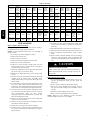
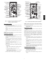
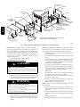
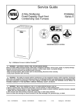
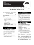
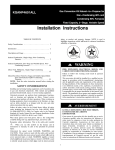
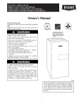
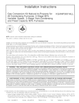
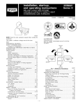
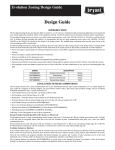
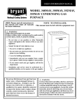
320720---751 thru ---761
Primary Cell Inlet Panel Kit
Installation Instructions
NOTE: Read the entire instruction manual before starting the
installation.
SAFETY CONSIDERATIONS
CUT HAZARD
Improper
installation,
adjustment,
alteration,
service,
maintenance, or use can cause explosion, fire, electrical shock, or
other conditions which may cause death, personal injury, or
property damage. Consult a qualified installer, service agency, or
your distributor or branch for information or assistance. The
qualified installer or agency must use factory--authorized kits or
accessories when modifying this product. Refer to the individual
instructions packaged with the kits or accessories when installing.
Follow all safety codes. Wear safety glasses, protective clothing,
and work gloves. Have a fire extinguisher available. Read these
instructions thoroughly and follow all warnings or cautions
include in literature and attached to the unit. Consult local
building codes, the current editions of the National Fuel Gas
Code (NFGC) NFPA 54/ANSI Z223.1 and the National
Electrical Code (NEC) NFPA 70.
In Canada, refer to the current editions of the National Standards
of Canada CAN/CSA--B149.1 and .2 Natural Gas and Propane
Installation Codes, and Canadian Electrical Code CSA C22.1
Failure to follow this caution may result in personal injury.
Sheet metal parts may have sharp edges or burrs. Use care
and wear appropriate protective clothing, safety glasses and
gloves when handling parts and servicing furnaces.
!
CAUTION
UNIT DAMAGE HAZARD
Failure to follow this caution may result in improper and
dangerous operation.
Label all wires prior to disconnection when servicing
controls.
INTRODUCTION
Recognize safety information. This is the safety--alert symbol .
When you see this symbol on the unit and in instructions or
manuals, be alert to the potential for personal injury.
Understand the signal words DANGER, WARNING, and
CAUTION. These words are used with the safety--alert symbol.
DANGER identifies the most serious hazards which will result in
severe personal injury or death. WARNING signifies hazards
which could result in personal injury or death. CAUTION is
used to identify unsafe practices which may result in minor
personal injury or product and property damage. NOTE is used
to highlight suggestions which will result in enhanced
installation, reliability, or operation.
!
CAUTION
!
This instruction covers installation of the Primary Cell Inlet Panel
Kit Part No. 320720--751, --753, --754, --755, --756, --757, --758,
--760 and --761 in 40--in. (1016 mm) tall, condensing gas
furnaces. See Table 1 for kit usage.
NOTE: A releasing agent such as PAM cooking spray or
equivalent (must not contain corn or canola oil, halogenated
hydrocarbons nor aromatic contents to prevent inadequate seal)
and RTV sealant (G.E. 162, G.E. 6702, or Dow--Corning 738)
are needed before starting installation. DO NOT substitute any
other type of RTV sealant. G.E. 162 (P771--9003) is available
through RCD in 3--oz tubes.
DESCRIPTION AND USAGE
WARNING
Use this Primary Cell Inlet Panel Kit when replacement of a
factory--installed primary cell inlet panel is required.
FIRE, EXPLOSION AND ELECTRICAL SHOCK
HAZARD
This Primary Cell Inlet Panel Kit contains the following items:
Failure to follow this warning could result in personal
injury, death and/or property damage.
Primary Cell Inlet Panel
1
Burner Box Gasket
1
Cell Mounting Screw No. 8D X 3/8--in.(10 mm) 25 max
Installation Instructions
1
Before installing or servicing system, always turn off main
electrical and gas supplies to unit and tag with appropriate
lockout. There may be more than one disconnect switch.
1
Table 1 – Kit Usage
UNIT
KIT PART
NO.
320720--- 751
320720--- 753
320720--- 754
Prior to S/N
3002A14578
320720--- 755
320720--- 756
320720
320720--- 757
320720--- 758
340AAV
340MAV
350AAV
350MAV
353AAV
490AAV
24040
36040
24060
36060
48060
36080
48080
--- --48100
60100
60120
60140
--- ---
58MSA
040--- 08
040--- 12
060--- 08
060--- 12
060--- 16
040--- 08
040--- 12
060--- 08
060--- 12
060--- 16
351DAS
--- ---
--- ---
--- ---
36060
42060
42060
36080
48080
36080
48080
36080
48080
--- ---
--- ---
080--- 12
080--- 16
080--- 12
080--- 16
--- ---
--- ---
--- ---
42080
(Series A)
--- ---
--- ---
--- ---
48100
60100
--- ---
48100
60100
60100
60100
60120
--- ---
60120
60120
60120
--- ---
--- ---
--- ---
42040
42040
100--- 16
100--- 20
120--- 20
140--- 20
--- ---
345MAV
24040
36040
24060
36060
48060
355MAV
--- ---
320720--- 760
60080
60080
60080
--- ---
42080
(Series B
and later)
60080
320720--- 761
After S/N
3002A14577
36080
48080
36080
48080
36080
48080
36080
48080
--- ---
355AAV
355BAV
355CAV
PG9UAA
58MCA
58MCB
58MEB
58MXA
58MXB
352AAV
352MAV
353BAV
PG9MXA
--- ---
42080
60080
--- ---
INSTALLATION
58MEC
58MTA
58MTB
58MVB
58UVB
58MVC
58MVP
--- ---
--- ---
--- ---
060--- 12
060--- 14
060--- 14
080--- 12
080--- 16
--- ---
--- ---
36080
48080
--- ---
--- ---
080--- 14
(Series
100)
--- ---
100--- 16
100--- 20
100--- 16
100--- 20
100--- 20
100--- 20
120--- 20
120--- 20
120--- 20
120--- 20
--- ---
040--- 14
040--- 14
--- ---
080--- 20
080--- 20
--- ---
080--- 12
080--- 16
080--- 12
080--- 16
080--- 12
080--- 16
080--- 14
080--- 20
--- ---
PG9MAA
PG9MAB
24040
36040
24060
36060
48060
48100
60100
60120
60140
--- ---
080--- 14
(Series
110 and
later)
080--- 20
60080
--- ---
36080
48080
16. If control center was removed from furnace casing, secure
control center (and J--box) to manifold for removal purposes only.
17. Disconnect field drain connection from condensate trap.
18. Disconnect drain and relief port tube from condensate trap.
19. Remove condensate trap from furnace casing or blower
shelf.
20. Remove whole cell panel assembly with heat exchanger,
burner box, inducer assembly, J--box (if applicable), and
control center (if applicable) attached through front of furnace.
Remove Whole Cell Panel Assembly
See Fig. 1 and Fig. 2 for furnace component locations. See Fig. 3
for expanded view of heating system components.
NOTE: Actual component locations may vary depending on
model and series.
1. Turn off gas and electrical supplies to furnace.
2. Remove main furnace door.
3. Remove blower access panel.
4. Disconnect field power supply wires from J--box.
5. Remove two screws securing J--box.
6. Remove two screws securing top filler panel and rotate
panel upwards to remove or allow the heat exchanger to
be removed from front of furnace.
7. Disconnect combustion--air intake pipe from intake housing and move pipe out of furnace casing.
8. Disconnect gas supply pipe from gas valve using backup
wrench.
9. Disconnect vent pipe from inducer housing by loosening
coupling clamp on inducer outlet. If coupling has 2
clamps, loosen clamp on vent pipe side. Move pipe out of
furnace casing.
10. If control center is located in burner compartment of furnace, remove blower motor leads, transformer wires, door
switch wires, and auxiliary limit switch wires (if present)
from control center and pull wires through blower shelf.
11. If control center is located in blower compartment of furnace, disconnect wires from flame sensor, hot surface igniter, overtemperature switch, gas valve, pressure
switch(es), inducer motor, limit switch, and J--box, then
pull wires through blower shelf.
12. Remove two screws securing blower to blower shelf (four
screws on 120 and 140 sizes).
13. Remove two screws next to blower mounting screws that
secure blower shelf to cell panel.
14. Remove three screws from each side of cell panel.
15. If control center is located in burner compartment of furnace, remove control center by removing screw and pressing tabs inward.
!
CAUTION
PERSONAL INJURY HAZARD
Failure to follow this caution may result in personal injury.
Whole cell panel assembly is heavy. Get help to remove and
lift assembly.
Remove Burner Box Assembly
1. If not previously disconnected, disconnect wires or connectors to overtemperature switch, gas valve, igniter, and
flame sensor.
2. Remove pressure switch tube from intake housing.
3. Remove two screws attaching intake housing to burner
box, and rotate intake housing away from burner box for
removal.
4. Disconnect pressure tubing from gas valve.
5. Remove screws attaching burner box to cell panel.
NOTE: Burner box cover, manifold, gas valve, and burner
assembly should be removed as one assembly.
2
GAS VALVE
AUXILIARY
JUNCTION BOX
VENT OUTLET
CONDENSING
HEAT
EXCHANGER
(BEHIND CELL
INLET PANEL)
PRESSURE
SWITCHES
INDUCER MOTOR
CONDENSATE
TRAP
MOTOR AND
BLOWER
ASSEMBLY
PRIMARY HEAT
EXCHANGER
(BEHIND CELL
INLET PANEL)
BURNER
ENCLOSURE
COMBUSTIONAIR INTAKE
CONNECTION
PRIMARY HEAT
EXCHANGER
(BEHIND CELL
INLET PANEL)
AUXILIARY
JUNCTION BOX
CAP AND
CLAMP
(UNUSED
DRAIN
CONNECTION)
VENT OUTLET
INDUCER MOTOR
WIRE
CONNECTOR
CONDENSING
HEAT
EXCHANGER
(BEHIND CELL
INLET PANEL)
VENT OUTLET
CONTROL
CENTER
BLOWER
ACCESS PANEL
SAFETY
INTERLOCK
SWITCH
INDUCER
HOUSING
DRAIN TUBE
CONDENSATE
TRAP
AIR FILTER AND
RETAINER
AIR FILTER
AND RETAINER
A01026
BURNER
ENCLOSURE
GAS VALVE
CAP AND
CLAMP
(UNUSED
DRAIN
CONN.)
INDUCER
MOTOR
VENT
OUTLET
PRESSURE
SWITCHES
CONTROL
CENTER
BLOWER
ACCESS
PANEL
SAFETY
INTERLOCK
SWITCH
MOTOR AND
BLOWER ASSEMBLY
A93407
Fig. 1 -- Two--Stage, Two--Speed and Fixed--Capacity
Model(s) in Upflow Orientation
Fig. 2 -- Variable--Speed Model in Upflow Orientation
Remove Inducer Assembly
1. If not previously disconnected, disconnect inducer motor
wire connector at quick--connect.
2. If not previously disconnected, disconnect pressure switch
wires.
3. Remove collector box pressure switch tube from pressure
switch.
4. Remove four screws attaching inducer housing to cell panel.
NOTE: Inducer housing, inducer motor, and pressure switch(es)
should be removed as 1 assembly.
Install Primary Cell Inlet Panel
1. Remove four screws attaching condensing heat exchanger
assembly to primary cell inlet panel.
2. Remove screws attaching primary cells to primary cell inlet panel.
3. Remove main limit and shield from primary cell inlet panel. Note orientation of shield and direction of main limit
for reassembly.
4. Remove primary cell inlet panel by lifting panel off condensing heat exchanger collector box.
5. Slide new inlet cell panel over condensing heat exchanger
collector box.
6. Attach primary cell inlet panel to primary cells by doing
the following:
a. Center primary cell inlet panel over primary cell openings.
b. Use an awl to align holes and start ALL screws
(provided in kit) in primary cells.
c. After all screws are started, check position of fiberglass
gasket and tighten screws in cells.
7. Install main limit and shield in primary cell inlet panel.
NOTE: Visually check location of main limit and shield to
ensure shield is not touching primary cells. If shield is touching,
short cycling of limit will occur.
8. Reinstall condensing heat exchanger assembly to primary
cell inlet panel.
Reinstall Inducer Assembly
1. Inspect connector box gasket where inducer housing will
mate.
NOTE: If gasket is damaged in any way, it must be repaired. To
repair, apply a small bead of G.E. RTV 162, G.E. 6702, or
Dow--Corning RTV 738 to damaged gasket area. Apply sealant
releasing agent such as PAM cooking spray or equivalent (must
not contain corn nor canola oil, halogenated hydrocarbons or
aromatic content to prevent inadequate sealing) to inducer
housing mating surface.
2. Attach inducer assembly to cell panel by aligning four
screws through inducer housing spacers. Tighten screws to
secure.
3. Attach collector box pressure switch tube to pressure
switch. See tubing diagram of furnace for proper location
attachment.
4. If control was removed from furnace with whole cell panel
assembly, reconnect inducer motor wire connector at
quick--connect.
5. If control was removed from furnace with whole cell panel
assembly, reconnect pressure switch wires. Refer to wiring
diagram on furnace for proper attachment.
Reinstall Burner Enclosure Assembly
1. Position burner enclosure gasket between the burner box
and inlet cell panel and secure burner box on inlet cell
panel using screws removed earlier.
2. Connect pressure tube to gas valve.
3. Inspect gasket, then install intake housing on burner enclosure.
3
320720
COMBUSTION-AIR
INTAKE
CONNECTION
PRIMARY CELL
INLET PANEL
PRIMARY
CELL
COLD SPOT
BAFFLE
COUPLING
BOX
MAIN LIMIT
SHIELD
T-TABS
MAIN LIMIT
BURNER
ENCLOSURE
GASKET
BLOWER
SHELF
320720
CONDENSING
HEAT EXCHANGER
CELL REAR PANEL
PRIMARY CELL
OUTLET PANEL
CONDENSING
HEAT EXCHANGER
ASSEMBLY
PRESSURE
SWITCH
BURNER
ENCLOSURE
AND GAS VAVLE
INDUCER
MOTOR
NOTE: ACTUAL COMPONENT LOCATION MAY VARY
DEPENDING ON MODEL & SERIES.
A05128
Fig. 3 -- Expanded View of Heat System Components in Upflow Orientation
NOTE: If gasket is damaged in any way, it must be repaired. To
repair, apply a small bead of G.E. RTV 162, G.E. 6702, or
Dow--Corning RTV 738 to damaged gasket area. Apply sealant
releasing agent such as PAM cooking spray or equivalent (must
not contain corn nor canola oil, halogenated hydrocarbons or
aromatic content to prevent inadequate sealing) to burner
enclosure mating surface.
4. Connect pressure tube to intake housing.
Reinstall Whole Cell Panel Assembly
!
NOTE: When reinstalling condensing heat exchanger assembly,
the lower flange of the condensing heat exchanger cell rear panel
must engage on the T--tabs in rear blower shelf. (See Fig. 3.)
3. Install three screws to each side of inlet cell panel and into
cell panel supports.
4. If previously removed, reinstall control center in casing
flange.
5. If control center is located in burner compartment or furnace, reinstall blower motor leads, transformer wires, door
switch wires, and auxiliary limit switch wires (if present)
through blower shelf and grommet.
6. If control is located in blower compartment of furnace,
pull wires to flame sensor, hot surface igniter, overtemperature switch, gas valve, pressure switch(es), inducer motor,
limit switch, and J--box through blower shelf.
7. Install J--box.
8. Reattach wires to control center or components. See wiring diagram on furnace for proper attachment.
9. Reinstall condensate trap where previously installed furnace casing or blower shelf.
10. Reconnect condensate trap drain tubes. See tubing diagram on furnace for proper tube location.
11. Connect field drain to condensate trap.
NOTE: Ensure tubes are not kinked or pinched, as this will
affect operation.
12. Connect vent pipe by inserting pipe into coupling, elastomeric (rubber) coupling, and then fully into inducer housing outlet.
13. Connect combustion--air intake pipe to intake housing and
install screw to secure. Do not use RTV unless previously
used.
14. Install top filler panel.
15. Install gas supply pipe to gas valve using backup wrench.
CAUTION
PERSONAL INJURY HAZARD
Failure to follow this caution may result in personal injury.
Whole cell panel assembly is heavy. Get help to lift and
install.
1. Install whole cell panel assembly with heat exchanger,
burner box, inducer assembly, J--box (if applicable), and
control center (if applicable) through front of furnace.
!
WARNING
FIRE AND UNIT OPERATION HAZARD
Failure to follow this warning could result in personal
injury, death and / or property damage.
DO NOT cut or tear foil face insulation. If cuts or tears
occur, repair insulation with foil tape.
2. Secure whole cell panel assembly to blower shelf by installing two screws through blower housing (four screws
on 120 and 140 sizes) and two screws next to blower
housing.
4
NOTE: Use propane gas--resistant pipe dope to prevent gas leaks
DO NOT use Teflon tape.
!
WARNING
EXPLOSION AND FIRE HAZARD
Failure to follow this warning could result in personal
injury, death and/or property damage.
For upflow or downflow applications, gas valve knob
or switch must be facing forward or tipped to the UP
position.
Connect field power supply to J--box.
Install blower access panel.
Turn on gas and electrical supplies to furnace.
Check for gas leaks.
!
320720
16.
17.
18.
19.
WARNING
EXPLOSION AND FIRE HAZARD
Failure to follow this warning could result in personal
injury, death, and/or property damage.
Never test for gas leaks with an open flame. Use a
commercially available soap solution made specifically for
the detection of leaks to check all connections.
20. Check furnace operation through two cycles.
21. Check for condensate leaks.
22. Replace furnace door.
5
320720
Copyright 2010 CAC / BDP S 7310 W. Morris St. S Indianapolis, IN 46231
Printed in U.S.A.
Edition Date: 09/10
Manufacturer reserves the right to change, at any time, specifications and designs without notice and without obligations.
6
Catalog No: IIK320720---005
Replaces: IIK320720--004