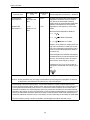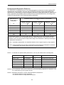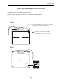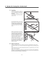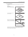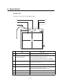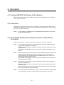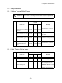
1
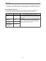
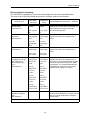
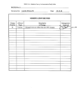
Digital Radiography
CXDI-55G
User’s Manual
Before using the instrument, be sure to read this manual thoroughly.
Also, read the manuals of other instruments in the system.
Keep the manual where it is easily accessible.
PLEASE NOTE
1.
The user is responsible for the use and maintenance of the product.
We suggest that a member of the user’s staff be designated as being in charge of maintenance so as to ensure that the product is kept in a safe and good condition.
Also, medical products must be used only by a qualified person.
2.
Roentgenography, image processing, reading of image, and storage of data must be performed in accordance with the law of the country where the product is being used.
Also, the user is responsible for maintaining the privacy of image data.
3.
In no event will Canon be liable for direct or indirect consequential damage arising out of
the use of this product. Canon will not be liable for loss of image data due to any reason.
4.
This product may malfunction due to electromagnetic waves caused by portable personal
telephones, transceivers, radio-controlled toys, etc. Be sure to avoid having objects such
as these, which affect this product, brought near the product.
5.
Disposal of this product in an unlawful manner may have a negative impact on health and
on the environment. When disposing of this product, therefore, be absolutely sure to follow the procedure which is in conformity with the laws and regulations applicable in your
area.
6.
Canon reserves the right to change the specifications, configuration and appearance of
the product without prior notice.
European Union (and EEA*) only.
This symbol indicates that this product is not to be disposed of with your
household waste, according to the WEEE Directive (2002/96/EC) and your
national law. This product should be handed over to a designated collection
point, e.g., on an authorized one-for-one basis when you buy a new similar
product or to an authorized collection site for recycling waste electrical and
electronic equipment (EEE). Improper handling of this type of waste could
have a possible negative impact on the environment and human health due
to potentially hazardous substances that are generally associated with EEE.
At the same time, your cooperation in the correct disposal of this product will
contribute to the effective usage of natural resources. For more information
about where you can drop off your waste equipment for recycling, please
contact your local city office, waste authority, approved WEEE scheme or
your household waste disposal service.
For more information regarding return and recycling of WEEE products,
please visit www.canon-europe.com.
* EEA : Norway, Iceland and Liechtenstein
•
System and product names in this manual are the trademarks of each manufacturer that developed them.
© CANON INC. 2009
All rights reserved.
Under copyright laws, this manual may not be copied, in whole or in part, without the written
consent of Canon.
Safety Information
Regulations
This instrument conforms to IEC 60601-1-2:2001.
For U.S.A. and Canada
• This instrument is a CLASS I EQUIPMENT according to UL60601-1 and CAN/CSA C22.2
No.601.1.
• The following mark indicates that the instrument is a Type B Applied Parts.
• The degree of protection against ingress of water is IPX0.
• This equipment is not suitable for use in the presence of a flammable anaesthetic mixture
with air or with oxygen or nitrous oxide.
• The mode of operation is Continuous Operation.
For EU Countries
• The following mark shows compliance of the instrument with Directive 93/42/EEC.
• This instrument has been classified into EN55011 Group 1/Class A.
• This instrument is a CLASS I EQUIPMENT according to EN 60601-1.
• The following mark indicates that the instrument is a Type B Applied Parts.
• The degree of protection against ingress of water is IPX0.
• This equipment is not suitable for use in the presence of a flammable anaesthetic mixture
with air or with oxygen or nitrous oxide.
• The mode of operation is Continuous Operation.
(1)
Safety Information
Guidance and Manufacturer’s Declaration for EMC Directive
Electromagnetic Emissions
The CXDI-55G is intended for use in the electromagnetic environment specified below.
The user of the CXDI-55G should assure that it is used in such an environment.
Emission Test
Compliance
Electromagnetic Environment – Guidance
RF emissions
CISPR 11
GROUP 1
The CXDI-55G uses RF energy only for its internal function. Therefore, its RF emissions are very low and are not
likely to cause any interference in nearby electromagnetic
equipment.
RF emissions
CISPR 11
Class A
Harmonic emissions
IEC 61000-3-2
Complies
The CXDI-55G is suitable for use in all establishments
other than domestic and those directly connected to the
public low-voltage power supply network that supplies
buildings used for domestic purposes.
Voltage fluctuations/
flicker emissions
IEC 61000-3-3
Complies
(2)
Safety Information
Electromagnetic Immunity
The CXDI-55G is intended for use in the electromagnetic environment specified below.
The user of the CXDI-55G should assure that it is used in such an environment.
Immunity Test
Electrostatic discharge (ESD)
IEC 61000-4-2
Electrical fast transient/burst
IEC 61000-4-4
Surge
IEC 61000-4-5
Voltage dips, short
interruptions and voltage variations on
power supply input
lines
IEC 61000-4-11
Power frequency
(50/60Hz) magnetic
field
IEC 61000-4-8
IEC 60601
Test Level
Compliance
Level
±(2, 4, 6) kV
contact
±(2, 4, 6) kV
contact
±(2, 4, 8) kV
air
±(2, 4, 8) kV
air
±2 kV for
power supply
lines
±2 kV for
power supply
lines
±1 kV for
input/output
lines
±1 kV for
input/output
lines
±1 kV differential mode
±1 kV differential mode
±2 kV common mode
±2 kV common mode
<5% UT
(>95% dip in
UT) for 0.5
cycle.
<5% UT
(>95% dip in
UT) for 0.5
cycle.
40% UT
(60% dip in
UT) for 5
cycles
40% UT
(60% dip in
UT) for 5
cycles
70% UT
(30% dip in
UT) for 25
cycles
70% UT
(30% dip in
UT) for 25
cycles
<5% UT
(>95% dip in
UT) for 5 sec.
<5% UT
(>95% dip in
UT) for 5 sec.
3 A/m
3 A/m
Electromagnetic Environment – Guidance
Floors should be wood, concrete or
ceramic tile. If floors are covered with synthetic material, the relative humidity
should be at least 30%.
Mains power quality should be that of a
typical commercial or hospital environment.
Mains power quality should be that of a
typical commercial or hospital environment.
Mains power quality should be that of a
typical commercial or hospital environment. If the user of the CXDI-55G requires
continued operation during power mains
interruptions, it is recommended that the
CXDI-55G be powered from an uninterruptible power supply or a battery.
Power frequency magnetic fields should
be at levels characteristic of a typical location in a typical commercial or hospital
environment.
NOTE: UT is the a.c. mains voltage prior to application of the test level.
(3)
Safety Information
Immunity Test
IEC 60601 Test
Level
Compliance
Level
Conducted RF
IEC 61000-4-6
3 Vrms
150 kHz to 80
MHz
3Vrms
Radiated RF
IEC 61000-4-3
3 V/m
80 MHz to 2.5
GHz
3 V/m
Electromagnetic Environment – Guidance
Portable and mobile RF communications
equipment should be used no closer to
any part of the CXDI-55G, including
cables, than the recommended separation
distance calculated from the equation
applicable to the frequency of the transmitter.
Recommended separations distance
d = 1.2 P
d = 1.2 P 80 MHz to 800 MHz
d = 2.3 P 800MHz to 2.5 GHz
where P is the maximum output power rating of the transmitter in watts (W) according to the transmitter manufacturer and d
is the recommended separation distance
in metres (m).
Field strengths from fixed RF transmitters,
as determined by an electromagnetic site
surveya, should be less than the compliance level in each frequency rangeb.
Interference may occur in the vicinity of
equipment marked with the following symbol:
NOTE 1: At 80 MHz and 800 MHz, the higher frequency range applies.
NOTE 2: These guidelines may not apply in all situations. Electromagnetic propagation is affected
by absorption and reflections from structures, object and people.
a
Field strengths from fixed transmitters, such as base stations for radio (cellular/cordless) telephones and land mobile radios, amateur radio, AM and FM radio broadcast and TV broadcast cannot be predicted theoretically with accuracy. To assess the electromagnetic environment due to
fixed RF transmitters, an electromagnetic site survey should be considered. If the measured field
strength in the location in which the CXDI-55G is used exceeds the applicable RF compliance level
above, the CXDI-55G should be observed to verify normal operation. If abnormal performance is
observed, additional measures may be necessary, such as reorienting or relocating the CXDI-55G.
b
Over the frequency range 150 kHz to 80 MHz, field strengths should be less than 3 V/m.
(4)
Safety Information
Recommended Separation Distances
The CXDI-55G is intended for use in an electromagnetic environment in which radiated RF
disturbances are controlled. The user of the CXDI-55G can help prevent electromagnetic
interference by maintaining a minimum distance between portable and mobile RF communications equipment (transmitters) and the CXDI-55G as recommended below, according to the
maximum output power of the communications equipment.
Rated maximum
output power of
transmitter
Separation distance according to frequency of transmitter
m
150 kHz ~ 80 MHz
80 MHz ~ 800 MHz
800 MHz ~ 2.5 GHz
W
d = 1 .2 P
d = 1 .2 P
d = 2 .3 P
0.01
0.12
0.12
0.23
0.1
0.38
0.38
0.73
1
1.2
1.2
2.3
10
3.8
3.8
7.3
100
12
12
23
For transmitters rated at a maximum output power not listed above, the recommended separation
distance d in metres (m) can be estimated using the equation applicable to the frequency of the
transmitter, where P is the maximum output power rating of the transmitter in watts (W) according to
the transmitter manufacturer.
NOTE 1: At 80 MHz and 800 MHz, the separation distance for the higher frequency range applies.
NOTE 2: These guidelines may not apply in all situations. Electromagnetic propagation is affected
by absorption and reflection from structures, objects and people.
NOTE 1: To maintain the optimum EMC performance, use only the cables which are designated.
Name
Type of shield
Length
Notes
Power cable
Non-shielded
3m
Provided with Power Box
Sensor cable
Shielded
7.8 m
Provided with the Sensor Unit
X-ray interface cable
Non-shielded
20 m
Provided with Power Box
Remote switch cable
Non-shielded
20 m
Provided with Power Box
LAN cable
Non-shielded
Max. 20 m
Not provided
NOTE 2: Do not install the CXDI-55G and Power Box (CXDI SYSTEM II) adjacent to or stacked on top
of or underneath any other system devices.
NOTE 3: Essential Performance in terms of Electromagnetic Disturbances
• No adverse effects on image acquisition
• No adverse effects on image data transmission
(5)
Safety Information
General Safety Information
Follow the safety instructions in this manual and all warnings and cautions printed on the warning
labels. Ignoring such cautions or warnings while handling the product may result in injury or accident.
Be sure to read and fully understand the manual before use.
Keep this manual for future reference.
Meaning of Caution Signs
! WARNING
This indicates a potentially hazardous situation which, if not heeded, could
result in death or serious injury to you or others.
! CAUTION
This indicates hazardous situation which, if not heeded, may result in minor or
moderate injury to you or others, or may result in machine damage.
NOTE
This is used to emphasize essential information.
Be sure to read this information to avoid incorrect operation.
Installation and Environment of Use
! WARNING
Do not use or store the instrument near any flammable chemicals such as
alcohol, thinner, benzine, etc. Also, this instrument is not a category AP or
APG equipment. If chemicals are spilled or evaporate, it may result in fire or
electric shock through contact with electric parts inside the instruments. Also,
some disinfectants are flammable.
Be sure to take care when using them.
! CAUTION
Do not install the instrument in a location with the conditions listed below.
Otherwise, it may result in failure or malfunction, fall or cause fire or injury.
• Close to facilities where water is used.
• Where it will be exposed to direct sunlight.
• Close to air-conditioner or ventilation equipment.
• Close to heat source such as a heater.
• Prone to vibration.
• Insecure place.
• Dusty environment.
• Saline or sulfurous environment.
• High temperature or humidity.
• Freezing or condensation.
Installation Operation
! WARNING
Do not connect the instrument with anything other than specified.
Otherwise, it may result in fire or electric shock.
(6)
Safety Information
Power Supply
! WARNING
Be sure to turn OFF the power of each instrument before connecting or disconnecting the cables.
Also, do not handle them with wet hands. Otherwise, you may get an electric
shock that may result in death or serious injury.
! WARNING
Be sure to hold the plug or connector to disconnect the cable.
If you pull the cable, the core wire may be damaged, resulting in fire or electric
shock.
! WARNING
Do not cut or process the cables. Also, do not place anything heavy, including
the instrument on it, step on it, pull it, bend it, or bundle it.
Otherwise, the cable may be damaged, which may result in fire or electric
shock.
! WARNING
Do not turn ON the system power when condensation is formed on the instrument. Otherwise, it may result in fire or electric shock.
! CAUTION
Because the instrument’s cable is long, take care so cables do not get tangled
during use. Also, be careful not to get your feet caught in the cable.
Handling
! WARNING
Always be sure to keep checking the condition of the system and the patient
to ensure they are normal during the use of the instrument.
If any problem is found, take appropriate measures, such as stopping the
operation of the instrument, as required.
! WARNING
Never disassemble or modify the product as it may result in fire or electric
shock. Also, since the instrument incorporates parts that may cause electric
shocks and other hazardous parts, touching them may cause death or serious
injury.
! WARNING
Do not hit or drop the instrument. The instrument may be damaged if it
receives a strong jolt, which may result in fire or electric shock if the instrument is used without it being repaired.
! CAUTION
Do not spill liquid or chemicals onto the instrument or, in cases where the
patient is injured, allow it to become wet with blood or other body fluids, as
doing so may result in fire or electric shock. In such situation, protect the
instrument with disposable covering as necessary.
! CAUTION
Wipe the CFRP plate of the sensor unit with ethanol or glutaraldehyde solution to disinfect it each time a different patient uses the instrument, in order to
prevent infection.
If the optional grid unit is being used, disinfect its surface.
Please consult a specialist for the procedure for disinfection.
! CAUTION
Turn off the power of each instrument for safety when they are not going to be
used.
(7)
Safety Information
When Problem Occurs
! WARNING
Should any of the following occur, immediately turn OFF the power of each
instrument, unplug the power cable from the AC outlet, and contact Canon
representative or distributor.
• When there is smoke, odd smell or abnormal sound.
• When liquid has been spilled into the instrument or a metal object has
entered through an opening.
• When the instrument has been dropped and it is damaged.
Maintenance and Inspection
! WARNING
For safety reasons, be sure to turn OFF the power of each instrument when
the inspections indicated in this manual are going to be performed.
Otherwise, it may result in electric shock.
! WARNING
When the instrument is going to be cleaned, be sure to turn OFF the power of
each instrument, and unplug the power cable from the AC outlet.
Never use alcohol, benzine, thinner or any other flammable cleaning agents.
Otherwise, fire or electric shock may result.
! WARNING
The instrument must be repaired by a qualified engineer only.
If it is not repaired properly, it may cause fire, electric shock, or accident.
! CAUTION
For safety reasons, be sure to inspect the instrument before using it.
In addition, carry out a regular inspection at least once a year.
(8)
Safety Information
Labels and Markings on the Instrument
The CXDI-55G has a few labels and markings on it.
Contents of those and positions where they are attached are indicated below.
Sensor Unit
Front
This mark indicates that this is a Type B Applied Part
according to UL60601-1 and EN60601-1.
This unit can be installed in the patient environment.
These marks indicate that the instrument
must be handled with care.
Do not jolt or apply excessive load to the
instrument.
Rear
Name Label
(9)
Contents
Safety Information .................................................................................................... (1)
Regulations ................................................................................................................................(1)
Guidance and Manufacturer’s Declaration for EMC Directive ................................................... (2)
General Safety Information ........................................................................................................ (6)
Labels and Markings on the Instrument .....................................................................................(9)
1. Overview .................................................................................................................1
2. Notes for Using the Instrument ...............................................................................2
3. Description ..............................................................................................................5
4. Operation ................................................................................................................6
4.1 Turning ON/OFF the Power of the System ........................................................................... 6
4.2 Calibration ............................................................................................................................. 6
4.3 Connecting and Disconnecting the Sensor Cable Relay Connector .................................... 6
5. Inspection and Maintenance ...................................................................................8
5.1 Inspection ............................................................................................................................. 8
5.2 Cleaning .............................................................................................................................. 11
6. Service Information ...............................................................................................12
7. Specifications .......................................................................................................13
7.1 Main Specifications ............................................................................................................. 13
7.2 Characteristics .................................................................................................................... 14
8. Components ..........................................................................................................16
9. Dimensions ...........................................................................................................17
Appendix: Attaching the Optional Grid Unit ...............................................................18
1. Overview
The Canon Digital Radiography CXDI-55G is a portable digital radiography that can
take images of any part of the body.
It directly converts the X-ray images captured by the LANMIT (Large Area New MIS
Sensor and TFT) sensor into a high-resolution digital images.
The instrument is suited for use inside a patient environment.
–1–
2. Notes for Using the Instrument
(1) Handling
Handle the instrument carefully, as
it may be damaged if something is
hit against it, dropped, or receives a
strong jolt.
Also, handle the optional grid unit
with care too.
Do not pull the cable. Also, do not
pull the sensor unit when the cable
is tangled with something. Otherwise, the cable may be damaged,
which may result in fire or electric
shock.
When transporting the instrument,
do not allow the sensor cable relay
connector to drag on the floor or
ground or bump against anybody or
any articles of property. It is recommended to hold the cable while
transporting the instrument.
Otherwise, the connector get caught
by, bump against somebody resulting in injury or cause damage to the
property items and/or connector
itself as a result.
(2) Before Exposure
Sudden heating of the room in cold areas will cause condensation to form on the
instrument. In this case, wait until condensation disappears before performing exposure.
If the instrument is used with condensation formed on it, problems may occur in the
quality of the instrument.
When an air-conditioner is going to be used, be sure to raise/lower the temperature
gradually so that a difference in temperature in the room and in the instrument does
not occur, to prevent forming of condensation.
–2–
2. Notes for Using the Instrument
(3) During Exposure
Do not apply excessive weight to the sensor unit. Otherwise, the sensor may be
damaged.
Limit of Load
Uniform load: 150 kg over the
whole area of sensor unit surface.
Local load: 100 kg on an area
40 mm in diameter.
Be sure to use the sensor unit on a
flat place so it will not bend. Otherwise, the sensor may be damaged.
Perform exposure after checking that the exposure conditions are optimally suited to
this product. The sensitivity of the sensor differs depending on the product.
This is also different from the CXDI-55C.
–3–
2. Notes for Using the Instrument
(4) During Cleaning
Do not use anything other than neutral detergent for cleaning the cover of the instrument. Otherwise, the coating will be corroded.
(5) Storage
Be sure to store the sensor unit and the optional grid unit in a safe place where it will
not fall or drop.
(6) Others
Be sure to reconnect the cables to the proper connectors. Otherwise, the instrument
may malfunction or may be damaged.
For U.S.A.
Rx only-Caution:
Federal law restricts this device to sale by or on the order of a licensed practitioner.
Intended Use:
Canon digital radiography CXDI-55G provides digital image capture for conventional film/screen radiographic examinations.
The device is intended to replace radiographic film/screen systems in all general
purpose diagnostic procedures.
This device is not intended for mammography applications.
For European Union
Intended Use:
This device provides digital X-Ray image for diagnosis of disease, injury, or any
applicable health problem. The image is obtained as the result of imaging X-ray
passed through human body with the X-ray flat panel detector and importing digital
signals output from the detector into the image processor.
–4–
3. Description
Sensor Unit
This unit converts the X-rays into digital signals.
a
d
b
e
c
f
g
Name
Description
a
Grip
Hold this grip when carrying the sensor unit.
b
CFRP (Carbon Fiber Reinforced Plastic) plate
The part of the patient’s body to which an image is to be
taken should be placed against this plate.
This plate should be disinfected each time a different
patient uses the instrument in order to prevent infection.
c
Sensor cable
Connect this cable to the power box (sold separately)
through the relay connector.
d
BUSY lamp
Lights when the sensor unit is busy communicating.
e
SENSOR lamp
Blinks while the instrument is being readied for exposures and when errors have occurred.
Lights when the instrument is ready for exposures.
f
POWER lamp
Lights when the power of sensor unit is ON.
g
Effective capture area border
Indicates the effective capture area.
–5–
4. Operation
4.1 Turning ON/OFF the Power of the System
When turning ON/OFF the power of the sensor unit, refer to the Power Box (sold separately) Operation Manual.
4.2 Calibration
Calibration is important to ensure that a good image is achieved with the CXDI-55G by
obtaining the calibration data of the sensor unit. Perform calibration when exposure conditions have changed significantly.
NOTE:
For procedure for calibrating, refer to “Calibrating the Instrument” in the CXDI
Series Operation Manual.
4.3 Connecting and Disconnecting the Sensor Cable Relay
Connector
Follow the steps below to connect or disconnect the sensor cable relay connector.
NOTE:
Do not connect this sensor unit to the power box other than CXDI SYSTEM II.
It may cause damage to the connector.
In addition, it is necessary to register each sensor unit to the software for controlling the system.
For details on registering the sensor unit, contact Canon representative or distributor.
NOTE:
When connecting or disconnecting the sensor cable relay connector, refer to the
CXDI Series Operation Manual, set the power switch on the power box (or
remote switch) to OFF and check that the POWER lamps on the sensor unit,
power box and remote switch are off.
The ERROR lamp will light if the connector is connected or disconnected while
the POWER lamp is lighted.
NOTE:
Be absolutely sure to hold the sensor cable relay connector by its grip part to
connect or disconnect it.
Holding the cable to connect or disconnect the connector may break the wires
inside the cable.
If the outer bushing of the grip part is turned, the cable lock can be loosened, and
this can cause a short-circuit of the cable.
NOTE:
Do not drop the sensor cable relay connector when connecting or disconnecting
it. You may injure yourself or cause damage to the property or connector.
–6–
4. Operation
(1)
(2)
(3)
Align the positioning marks.
Align the positioning mark on the
connector at the sensor unit side
with the positioning mark on the
connector at the power box side,
and insert the connectors while
turning them slightly to the left or
right.
Push the connectors in by one
step.
Push them in until they click into
place.
Push the connectors in by
another step.
Push them firmly in until they click
into place again to lock them
together.
To disconnect the sensor cable relay connector:
Hold the grip parts of the connectors on
both sides, and pull the grip part on the
sensor unit side to release the lock. Now
pull the connectors to the left and right to
disconnect.
–7–
Sensor unit side
Positioning
mark
Grip part
Power box side
Locking latch
Positioning
mark
Grip part
2 to 3 mm
5. Inspection and Maintenance
!
WARNING
The instrument must be repaired by a qualified engineer only.
If it is not repaired properly, it may cause fire, electric shock, or
accident.
!
CAUTION
For safety reasons, be sure to inspect the instrument before using
it. In addition, carry out a regular inspection at least once a year.
5.1 Inspection
In order to ensure that the instrument is used safely and normally, please be sure to inspect
the instrument before use.
If any problem is found during the inspection, please take measures indicated in this chapter.
If problem still cannot be corrected, please contact Canon representative or distributor.
It is recommended that a record of the inspection be kept by making copies of the check
lists in this section, or making a separate check list.
–8–
5. Inspection and Maintenance
5.1.1 Daily Inspection
5.1.1.1 Before Turning ON the Power
!
WARNING
For safety reasons, be sure to turn OFF the power of each instrument when the following inspections are going to be performed.
Otherwise, it may result in electric shock.
Result
Sensor unit
Cable
Inspection
Remedy
Date
/
Date
/
Date
/
Check that cables are not
damaged or cover of cables
is not torn.
Good/Bad
Good/Bad
Good/Bad
Contact Canon or distributor if there is any problem.
Check that the plugs and
locks of connectors are not
loose.
Good/Bad
Good/Bad
Good/Bad
Fully insert the cables and
lock them.
Check that there are no
cracks in the holder (pull-out
part) of the sensor cable.
Good/Bad
Good/Bad
Good/Bad
Contact Canon or distributor if there are any cracks in
the holder.
Check that the cover or parts
are not damaged and not
loose.
Good/Bad
Good/Bad
Good/Bad
Contact Canon or distributor if there is any problem.
5.1.1.2 After Turning ON the Power
Result
General
Inspection
Remedy
Date
/
Date
/
Date
/
Check that POWER lamp is
lit.
Good/Bad
Good/Bad
Good/Bad
Perform test exposure.
Take measures if error message is displayed by referring to the CXDI Series
Good/Bad Good/Bad Good/Bad
Operation Manual. Contact
Canon or distributor if the
problem cannot be solved.
–9–
Connect the power cable and
sensor cable properly.
5. Inspection and Maintenance
5.1.2 Monthly Inspection
Perform the following inspection periodically more than once a month. Contact Canon
representative or distributor if there is any problem or if you cannot do it.
Result
General
Inspection
Check the performance of
the instrument by performing exposures using a phantom or a resolution chart, or
perform self-test.
Date
/
Date
/
Date
/
Remedy
Refer to the CXDI Series
Operation Manual for the
Good/Bad Good/Bad Good/Bad procedure for self-test. Contact Canon or distributor if
there is any problem.
5.1.3 Yearly Inspection
Perform the following inspection periodically more than once a year. Contact Canon representative or distributor if there is any problem or if you cannot do it.
Result
General
Inspection
Check the performance of
the instrument by performing exposures using a phantom or a resolution chart.
Date
/
Date
/
Date
/
Good/Bad
Good/Bad
Good/Bad
Remedy
Contact Canon or distributor
if there is any problem.
5.1.4 Calibration
Perform calibration when exposure conditions have changed significantly.
See the CXDI Series Operation Manual for the procedure for calibration.
– 10 –
5. Inspection and Maintenance
5.2 Cleaning
5.2.1 CFRP (Carbon Fiber Reinforced Plastic) Plate of the Sensor Unit
!
WARNING
Wipe the CFRP plate of the sensor unit with ethanol or glutaraldehyde solution to disinfect it each time a different patient uses the
instrument, in order to prevent infection.
If the optional grid unit is being used, disinfect its surface.
Please consult a specialist for the procedure for disinfection.
If you are using disinfectant other than those specified above, or
you are mixing another disinfectant with ethanol, please also consult a specialist, because they may harm the CFRP plate and grid
unit.
Disinfect the CFRP plate of the sensor unit each time a different patient uses the instrument. If the optional grid unit is being used, disinfect its surface.
5.2.2 Cover
!
WARNING
When the instrument is going to be cleaned, be sure to turn OFF
the power of each instrument, and unplug the power cable from
the AC outlet.
Never use alcohol, benzine, thinner or any other flammable cleaning agents. Otherwise, fire or electric shock may result.
Clean the cover by the following procedure if it is dirty.
(1)
Turn OFF the power of the power box.
Shut down the control computer, and press side “0” of the power switch.
(2)
Turn OFF the power of each instrument.
Turn OFF the power of each instrument if connected.
(3)
Unplug the power cables.
Unplug the power cables of each instrument from the AC outlet.
(4)
Wipe the cover using neutral detergent.
Wipe the cover with a piece of cloth soaked in neutral detergent diluted in water and
wrung dry.
(5)
Wipe out neutral detergent.
Wipe the cover with a piece of cloth soaked in water and wrung dry whenever neurtral detergent has been used.
– 11 –
6. Service Information
(1) Repair
If problem cannot be solved even after taking the measures indicated in chapter 5,
contact Canon representative or distributor for repair.
Please refer to the name label and let us have the following information:
Name of the unit: CXDI-55G
Serial number:
6-digit number indicated on the name label.
Phenomenon:
In detail.
(2) Limit for Supplying Performance Parts for Repair
Performance parts* of this product will be stocked for eight years after discontinuance of production, to allow for repair.
* Parts required to maintain the functioning of the product
– 12 –
7. Specifications
7.1 Main Specifications
Sensor Unit
Purpose
General radiography
Pixel size
160 × 160 µm
Image matrix size
2208 × 2688 pixels
Number of pixels
Approx. 5.9 million pixels
Dynamic range
Approx. 80 dB
Resolution
3.1 lp/mm
Gray scale
12-bit, 4,096 gray scale
Environmental requirements
Operation:
Temperature: +5 to +35 °C
Humidity: 30 to 75 %RH (no condensation)
Storage and transportation:
Temperature: -30 to +50 °C
Humidity: 10 to 60 %RH (no condensation)
Atmospheric pressure: 700 to 1060 hPa
Power
Supplied from the power box.
Dimensions and mass
480 (W) × 481 (H) × 15 (D) mm,
3.4 kg (excluding the sensor cable)
– 13 –
7. Specifications
7.2 Characteristics
(1) Required patient doses
Equivalent to exposure dose of 200 or 400 speed film/screen system.
(2) Sensitometric characteristics
100000
saturation
Output(LSB)
10000
1000
100
10
RQA5(70kVp+21mmAl)
1
0.01
0.1
1
10
100
1000
Image receptor air kerma(uGy)
(3) Presampled MTF
1
Presampling MTF
0.8
0.6
0.4
0.2
0
0
1
2
3
Spatial frequency(lp/mm)
– 14 –
4
5
7. Specifications
(4) DQE
1
DQE
0.05mR
0.5mR
5mR
0.1
0.01
0
0.5
1
1.5
2
Spatial frequency(lp/mm)
– 15 –
2.5
3
8. Components
Sensor unit (Sensor cable S150-55 provided) ...........................................1
Sensor cable P630......................................................................................1
System Equipment (sold separately)
Digital Radiography Power Box (CXDI SYSTEM II) (with Remote switch)
Grid unit for CXDI-55
Sensor cable
P630-PM: Secures the relay connector on the power box side to a stand etc.
SP780-55: Connects directly to the sensor unit and power box without using a relay
connector.
– 16 –
9. Dimensions
481
Sensor Unit
480
15
Unit: mm
– 17 –
Appendix: Attaching the Optional Grid Unit
Attach the optional grid unit to the sensor unit by the procedure indicated below.
NOTE:
Structure of grid unit is delicate. Do not drop, knock over, bend, or apply force or
jolt to it. Otherwise, the unit may be damaged.
When the grid unit is not in use, remove it from the sensor unit and store it in a
safe place where it will not fall.
Even if it is not extremely damaged, its characteristics may be changed, which
may cause a problem in image quality.
(1) Blow off the dust on the front and back of the grid unit.
(2) Place the sensor unit horizontally on a table.
(3) Hold the grid unit with both hands and
engage the hooks on the bottom of the
grid unit to the holes on the bottom of
the sensor unit.
Hook
(4) Gently set the grid unit over the sensor
unit. A click sound is heard when the
grid unit is locked properly.
NOTE:
Ensure that the grid unit is locked
before lifting the sensor unit. Otherwise, the grid unit will fall and
be damaged.
To remove the grid unit
Lift up the grid unit top by about
50 mm while pressing the lock of the
grid unit top in the direction of the
arrow. Now remove the grid unit by
sliding it downward.
– 18 –
Lock
CANON INC. Medical Equipment Group
30-2, Shimomaruko 3-chome, Ohta-ku, Tokyo, Japan
Telephone: (81)-3-3758-2111
CANON U.S.A., INC.
CANON MEDICAL SYSTEMS
15955 Alton Parkway, Irvine, CA 92618-3616, U.S.A.
Telephone: (1)-949-753-4160
CANON EUROPA N.V. Medical Products Division
Bovenkerkerweg 59-61, 1185 XB Amstelveen, The Netherlands
Telephone: (31)-20-545-8926
PUB. L-IE-4152
0609P0.001
Printed in Japan