1
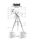
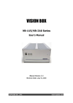
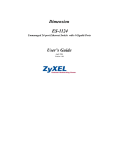
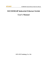
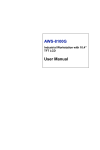
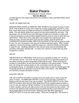
VOYAGER® 8 INCH DOBSONIAN TELESCOPE
MODEL 78-8000
9
1
8
2
3
7
4
6
5
1.
2.
3.
4.
5.
Rack & Pinion focusing System
Reflector Body
Altitude Bearing
Dobsonian Side Panel
Dobsonian Base (Azimuth Bearing)
6.
7.
8.
9.
Carry Handle
Primary Mirror
Finderscope
1.25" Format Eyepiec e
Never Look Directly At The Sun With Your Telescope
Permanent Damage To Your Eyes May Occur
Thank you for purchasing the Bushnell Voyager Dobsonian Telescope! Your new telescope has
been designed and crafted with the highest standards so that you may have years of enjoyment
and use out of this wonderful window to the heavens. This product comes complete with
everything you'll need to explore your universe including a professional parabolic primary
mirror, precision rack and pinion focusing mechanism, superior all-metal main telescope tube,
and professional quality wide-field 6x30 finderscope. Whether you are just starting out in
astronomy or you are an avid astronomer we wish you all the best with your telescope.
Please utilize this manual to its fullest potential by reading it completely before you attempt to
assemble and use your new telescope. Once assembled, we've included a basic guide on how to
get started in astronomy at the end of this manual. While this is not a complete guide, it will give
you some initial pointers. As you advance in ability, we would highly recommend a
supplemental star atlas, beginning astronomy guide, moon map, or any other guide as you travel
on your journey through the universe.
READ THROUGH ASSEMBLY INSTRUCTION
BEFORE YOU ASSEMBLE YOUR TELESCOPE
UNPACKING YOUR TELESCOPE
NOTE: YOUR DOBSONIAN TELESCOPE HAS BEEN SHIPPED IN TWO CARTONS.
PLEASE MAKE CERTAIN THAT YOU HAVE BOTH CARTONS (1 OF 2, 2 OF 2).
Carton 1 of 2: Includes the telescope tube and all accessories.
Carton 2 of 2: Includes the unassembled Dobsonian base and hardware.
TELESCOPE ASSEMBLY INSTRUCTIONS
Remove all components from the cartons and identify all components. You will need a phillips
screwdriver, and two adjustable wrenches for assembly.
ASSEMBLING THE DOBSONIAN BASE
1.
Remove the Dobsonian base components from the carton and verify that all five components
are included. You should have two circular pieces, two rectangular pieces with semi-circle
cut-outs, one rectangular piece, and a hardware package.
2.
Take the two rectangular pieces with semi-circle cut-outs and identify the side of each piece
with the countersunk pre-drilled holes. This side will face out when the base is assembled.
3.
Place one of the side panels (rectangular piece with semi-circle cut-out), making sure that the
proper side is facing out, against the front panel as shown in the diagram. Make sure that the
rubber bumper pads face in on the front panel. Line up the pre-drilled holes and insert two
screws through the side panels into the front panel. Note: the finished edge of the front
panel should face up. The two pieces should form a right angle. Tighten the screws and
countersink them until they are even with the side panel surface.
4.
Repeat this process with the other side panel. When complete, the support "box" will be
complete.
5.
Next insert the bolts from the inside of the "box" into the handles on the outside of the side
panel to firmly attach the handles to the side panels. Tighten completely.
6.
Insert the four supplied white caps over the four countersunk screws that hold the side
panels to the front panel to conceal the screw heads.
7.
Locate the circular component with the five drilled holes. This component is called the
azimuth bearing plate. Identify the side with the four outer countersunk holes like on the
other components. The side with the holes countersunk is the underside.
8.
Insert the remaining four screws through the azimuth bearing plate from the underside into
the corresponding pre-drilled holes in the bottom edges of the side panels on the previously
assembled "box" as shown in the diagram.
9.
Take the assembled "box" and azimuth bearing plate and turn it on its side. Locate the
remaining circular component called the bottom plate and the remaining hardware.
10. Take the bottom plate with rubber feet facing out and line it up with the hole in the center of
the azimuth bearing plate of the assembled "box"/azimuth bearing plate combination.
11. Insert the Nylon center bearing tube through the hole. Place a flat washer on each side.
Insert the Center Bolt from the bottom side and attach the hex nut on the top side. Tighten
enough to hold the base together yet loose enough to allow the base to turn easily.
Note: Your Bushnell Voyager Dobsonian Telescope Body comes pre-assembled from the
factory. No installation other than what is listed below is required.
ATTACH FINDERSCOPE AND TELESCOPE
1.
Remove Reflector Telescope Body (2) and Finderscope (8) from carton.
2.
Remove nuts located near the Rack & Pinion Focusing Mechanism (1) on Reflector Telescope
Body (2).
3.
Attach Finderscope (8) to Reflector Telescope Body (2) by inserting the screws extending
from the Reflector Telescope Body (2) into the holes in the base of the Finderscope (8).
4.
Refasten nuts so that Finderscope (8) is secure.
5.
Take Reflector Telescope Body (2) with attached Finderscope (8) and set them into the
Dobsonian base making certain that the Altitude Bearings (3) come to rest in the semi-circle
cradles on the side panels of the Dobsonian base. Note: The Finderscope (8) should be on
top of the Reflector Telescope Body (2) and the Bushnell® logo should be upright.
6.
Move the Dobsonian Telescope Assembly in both directions (up and down, and left and
right) to become familiarized with the unit. If the telescope doesn't move smoothly, review
the assembly process to verify you performed the assembly correctly.
THE FINAL STEPS
1.
Remove 1.25" Format Eyepiece (9) from carton.
2.
Insert into Rack & Pinion Focusing Mechanism (1).
3.
Remove Protective Dust Cover from end of telescope nearest the Rack & Pinion Focusing
Mechanism (1).
4.
Let the adventure begin.
Your Bushnell Telescope is now ready to be used. To obtain the fullest enjoyment from your
telescope, please refer to the following additional information.
Astronomical Telescopes are designed in such a way that the image you will see appear will be
UPSIDE DOWN and REVERSED, this is acceptable for viewing celestial bodies.
TELESCOPE USE
SELECTING AN EYEPIECE:
1. You should always start viewing with the lowest power eyepiece, which in this case is the 25
mm lens. Note: the base power of each eyepiece is determined by the focal length of the
telescope objective element, which for this model is 1000 mm. A formula can be used to
determine the power of each eyepiece: telescope OBJECTIVE mirror focal length
EYEPIECE focal length = MAGNIFICATION (e.g. Using the 25 mm lens, the calculation
would look like this: 1200 mm ÷ 25mm = 48x or 48 power.)
2.
Offered as an accessory for this telescope is a Barlow lens (model #78-0105). Barlow lenses
are used to double or triple the power of your telescope by placing your Barlow between the
focusing tube and the eyepiece. Using the example above, a 2x Barlow lens would give you a
total power of 96x or 96 power. (48 x 2 = 96x or 96 power). Other accessories available
include a 9mm eyepiece (model #78-0101) that would give you 133x or 133 power or 266x
when used in conjunction with the Barlow accessory and a standard camera adapter (model
#78-0104) for photographing the night sky.
FOCUSING TELESCOPE:
1. After inserting the eyepiece, aim the main telescope tube at a land-based target at least 200
yards away (e.g. A telephone pole or building). Fully extend focusing tube by turning Rack &
Pinion Focusing Mechanism (1)
2.
While looking through selected eyepiece (in this case the 25 mm), slowly retract focusing
tube by turning Rack & Pinion Focusing Mechanism (1) until object comes into focus.
ALIGNING FINDERSCOPE:
1. Look through low-power 1.25" format eyepiece (9) and establish a well-defined target (see
focusing telescope section).
2.
Looking through Finderscope (8), alternate tightening each Finderscope Adjustment Screw
surrounding the Finderscope (8) in the Finderscope Mount until crosshairs of Finderscope (8)
are precisely centered on the same object already centered in Main Telescope Tube's field of
view as seen through the 1.25" Format Eyepiece (9).
3.
Now, objects located first with the Finderscope (8) will be centered in the field of view of the
main telescope as seen through the 1.25" Format Eyepiece (9).
COLLIMATING THE TELESCOPE
Good alignment or collimation of the telescope's optical components will guarantee the most
optimum viewing. This telescope body comes preassembled from the factory and
precollimated. Therefore collimation should not be required. However, due to its great
importance there are a few steps that you can take to ensure that your telescope is properly
collimated.
1.
Remove the 1.25" Format Eyepiece (9) from the Rack and Pinion Focusing Mechanism (1).
2.
Look into the Rack and Pinion Focusing Mechanism (1) with the eyepiece removed. You will
see the secondary mirror located a few inches inside the end of the telescope tube (nearest the
Rack and Pinion Focusing Mechanism). Since it is a mirror, you will see a reflection of the
large primary mirror (7). That mirror will show an image of the secondary mirror and your
eye. Each image will be centered in a concentric set of images starting with the image of the
Primary Mirror (7), the secondary mirror, and your eye.
3.
Please refer to the diagram to see what to expect.
4.
If the image of your eye is centered in the reflection of the secondary mirror, your secondary
mirror is collimated. If it is off to one side, then secondary mirror adjustment will be
required. By removing the plastic cap on the secondary mirror base at the end of the
telescope tube nearest the Rack and Pinion Focusing Mechanism (1), you will see three screw
heads. They are positioned 120 degrees apart. By adjusting these three screws very slowly
and carefully, the secondary mirror will reflect an image of your eye that is perfectly centered
in the reflection of the secondary mirror. Once this is accomplished replace the plastic cap.
Your secondary mirror is now collimated.
5.
Once secondary mirror collimation is confirmed, you will need to verify Primary Mirror (7)
collimation. If the image of the secondary mirror is centered in the reflection of the primary
mirror, then your primary mirror is collimated. If it is off to one side, then Primary Mirror (7)
adjustment will be required. By locating the Primary Mirror (7) you will see three screw
heads on the bottom end of the telescope furthest from the Rack and Pinion Focusing
Mechanism (1). They are alsopositioned 120 degrees apart. By adjusting these three screws
very slowly and carefully, the Primary Mirror (7) will reflect an image of the secondary
mirror that is perfectly centered in the reflection of the Primary Mirror (7). Once this is
accomplished your Primary Mirror (7) is now collimated.
6.
Your telescope is now ready to deliver the best images possible.
Enjoying Your New Telescope
1. First determine your targeted object. Any bright object in the night sky is a good starting
point. One of the favorite starting points in astronomy is the moon. This is an object sure to
please any budding astronomer or experienced veteran. When you have developed
proficiency at this level, other objects become good targets. Saturn, Mars, Jupiter, and Venus
are good second steps to take.
2. The first thing you need to do after assembling the telescope as planned is center the desired
object in the finderscope's cross hairs. Provided you did a reasonable job aligning the
finderscope, a quick look through the main telescope tube at low power should reveal the
same image. With the lowest power eyepiece (the one with the largest number printed on it)
you should be able to focus the same image that you saw through the finderscope. Avoid the
temptation to move directly to the highest power. The low power eyepiece will give you a
wider field of view, and brighter image--thus making it very easy to find your target object.
At this point with a focused image in both scopes, you've passed the first obstacle. If you
don't see an image after attempting to focus it in, you might consider aligning your
finderscope again. Once you pass this step, you'll will enjoy the time spent ensuring a good
alignment. Every object you center in the finderscope will be easily found in the main
telescope tube, which is important for continuing your exploration of the night sky.
3. The low power eyepieces are perfect for viewing the full moon, planets, star clusters, nebulae,
and even constellations. These should build your foundation. However, for more detail, try
bumping up in magnification to higher power eyepieces on some of these objects. During
calm and crisp nights, the light/dark separation line on the moon (called the "Terminator") is
marvelous at high power. You can see mountains, ridges and craters jump out at you due to
the highlights.
Similarly, you can move up to higher magnifications on the planets and
nebulae. Star clusters and stars are best viewed through the low power no matter what.
4. The recurring astronomical theater we call the night sky is an ever-changing billboard. In
other words, not the same movie plays all the time. Rather, the positions of the stars change
not only hourly as they seem to rise and set, but also throughout the year. As the earth orbits
the sun our perspective on the stars changes on a yearly cycle about that orbit. The reason
the sky seems to move daily just as the sun and the moon "move" across our sky, is that the
earth is rotating about its axis. As a result you may notice that after a few minutes or a few
seconds depending on what power you are viewing at, the objects in your telescope will
move. At higher magnifications especially, you will notice that the moon or Jupiter will
"race" right out of the field of view. To compensate, just move the fine adjustment controls
on your telescope to "track" it in the necessary path.
Helpful Hints
1.
Your telescope is a very sensitive instrument. For best results and fewer vibrations set your
telescope up on a level location on the ground rather than your concrete driveway or your
wooden deck. This will provide a more stable foundation for viewing, especially if you've
drawn a crowd with your new telescope.
2.
If possible view from a location that has relatively few lights. This will allow you to see
much fainter objects. You'd be surprised how much more you'll see from your local lake or
park when compared to a backyard in the city.
3.
Using your telescope out a window is NEVER recommended.
4.
View objects that are high in the sky if possible. Waiting until the object rises well above the
horizon will provide a brighter and crisper image. Objects on the horizon are viewed
through several layers of earth's atmosphere. Ever wonder why the moon appears orange as
it sets on the horizon. It's because you are looking through a considerable more amount of
atmosphere than you would directly overhead. (Note: If objects high in the sky are distorted
or wavy, you are probably viewing on a very humid night.) During nights of unstable
atmosphere, viewing through a telescope can be frustrating if not impossible. Astronomers
refer to crisp, clear nights as nights of "good seeing."
Where do I start?
Your Bushnell telescope can bring the wonders of the universe to your eye. While this manual is
intended to assist you in the set-up and basic use of this instrument, it does not cover everything
you might like to know about astronomy. The first thing you need to do is get a very simple star
chart and a flashlight with a red bulb or red cellophane over the end. For objects other than stars
and constellations, a basic guide to astronomy is a must. Some recommended sources appear on
our website at www.bushnell.com. Also on our website will be current events in the sky for
suggested viewing. But, some of the standbys that you can see are:
The Moon--a wonderful view of our lunar neighbor can be enjoyed with any magnification. Try
viewing at different phases of the moon. Lunar highlands, lunar maria (lowlands called "seas"
for their dark coloration), craters, ridges and mountains will astound you.
Saturn--even at the lowest power you should be able to see Saturn's rings and moons. This is one
of the most satisfying objects in the sky to see simply because it looks like it does in pictures.
Imagine seeing what you've seen in textbooks or NASA images from your backyard!
Jupiter--the largest planet in our solar system is spectacular. Most noted features are its dark
stripes or bands both above and below its equator. These are the north and south equatorial
belts. Also interesting are Jupiter's four major moons. Pay close attention to their positions from
night to night. They appear to be lined up on either side of Jupiter.
Mars--The Great Red Planet appears as a reddish-orange disk. Look at different times of the year
and try to catch a glimpse of the white polar ice caps.
Venus--just like the moon, Venus changed phases from month to month. Some views of brilliant
Venus appear as if you were looking at a distant crescent moon.
Nebulae--The Great Orion Nebula is a very well known night sky object. This and many others
are brought to you by this telescope.
Star Clusters--View millions of stars densely packed in a cluster that resembles a ball.
Galaxies--One of the greatest and most interesting galaxies is our neighbor the Andromeda
Galaxy. Enjoy this and many others. Much, much, more!
www.bushnell.com
ANSWERS TO COMMONLY ASKED QUESTIONS
1. The image I see in the telescope is upside down and
reversed from right to left ?
• An upside-down and reversed image is a
common characteristic of most astronomical
telescopes. Since telescopes are used for
astronomical viewing orientation is not important.
The image in the finderscope will also be upside
down and reversed.
2.
How do I determine the power my telescope ?
• The power of your telescope can be determine
by dividing the focal length of the objective lens by
the focal length of the eyepiece. The eyepiece focal
length is the number printed on the eyepiece. (For
example: 1200 ÷ 25 = 48X)
3.
Where do I find the Telescope Focal Length
• The telescope focal length is the same focal
length as the objective focal length. For this
telescope it is 1200mm. Telescope focal lengths
range from 600mm to 1200mm on Bausch & Lomb
and Bushnell telescopes.
4.
What can I see with my telescope ?
• Telescopes with power ranging from 25X to
50X can be used to view Star Clusters and Nebulae.
90X to 120X telescope can view galaxies. Most
planets can be seen at any magnification.
5.
What do the numbers on the eyepiece mean ?
• The numbers on the eyepiece represents the
“focal Length” of the eyepiece.
TROUBLESHOOTING GUIDE
If after you have set-up your new telescope you are unable to see any objects, use this Quick
Reference guide to help you to understand the cause of the problem and quickly determine a remedy
1.
I’ve completed the set-up yet I cannot see anything
•
Check to see if objective lens cover and all
other lens covers have been removed.
•
Try to view an object that is 200 or more
yards away.
•
If there is more than one eyepiece included
with the telescope, use the lowest power
(highest number) eyepiece to begin viewing.
•
Use the Rack & Pinion Focusing Mechanism to
bring the object you are trying to view into
focus
Telescope LIFETIME LIMITED WARRANTY
Your telescope is warranted to be free of defects in materials and workmanship for the lifetime
of the original owner. The Lifetime Limited Warranty is an expression of our confidence in the
materials and mechanical workmanship of our products and is your assurance of a lifetime of
dependable service.
If your telescope contains electrical components the electronic components are warranted to be
free of defects in materials and workmanship for one year after the date of purchase.
In the event of a defect under this warranty, we will, at our option, repair or replace the
product, provided that you return the product postage prepaid. This warranty does not cover
damages caused by misuse or improper handling, installation or maintenance of the product.
Any return made under this warranty must be accompanied by the items listed below:
1) A check in the amount of $15.00 to cover the cost of handling
2) Name and address for product return
3) An explanation of the defect
4) Product should be well packed in a sturdy outside shipping carton to prevent
damage in transit and return postage prepaid to the address listed below:
IN U.S.A. Send To:
Bushnell * 8500 Marshall Drive * Lenexa, Kansas 66214
IN CANADA Send To:
Bushnell * 25A East Pearce Street, Unit 1 * Richmond Hill, Ontario L4B 2M9
For products purchased outside the United States and Canada please contact your local dealer
for applicable warranty information. This warranty gives you specific legal rights. You may
have other rights which vary from country to country.
©2001 Bushnell Performance Optics