1
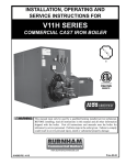
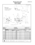
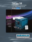
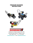
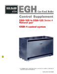
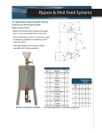
V11H Series
CAST IRON COMMERCIAL
WATER OR STEAM BOILER
UP TO 85%
THERMAL
EFFICIENCY
837 TO 5733
MBH INPUT
OIL, GAS
OR OIL/GAS
COMBINATION
30, 50 OR 80 PSI
CAST IRON
SECTIONAL
DESIGN
WATER OR STEAM
TOP OR REAR
VENTING
MAXIMIZE
EFFICIENCY WITH
SBC™ INTEGRATED
BOILER CONTROL
V11H Series CAST IRON COMMERCIAL WATER OR STEAM BOILER
Your Commercial Heating Solution!
Available in twenty sizes with gross output ratings from 674 to 4763
MBH, the V11H Series is commonly used in schools, hospitals, and
other large commercial applications where comfort and reliability
are critical. The product meets the energy efficiency requirements
of ASHRAE 90.1 with thermal efficiencies up to 85%.
Cast iron construction, ease of assembly, two venting options, and
stringent testing methods make the V11H Series boiler by Burnham
Commercial your commercial heating solution.
American-Made Cast Iron Construction
PAGE
2
Burnham Commercial’s unique cast iron
formula has an extremely high silicon
content, making it stronger and more
flexible. It offers better thermal shock
resistance and greater heat transfer
capabilities than other cast iron products. • MANUFACTURED WITH QUALITY
Casting Solutions operates a state-ofthe-art foundry, in Zanesville, Ohio,
ensuring quality and availability of
boiler sections.
• C AST IRON NIPPLE DIFFERENCE
V11H sections are held together using
cast iron nipples, which are well known
as being of the highest standard for
boiler construction. Unlike gaskets used
by many other boiler manufacturers,
cast iron nipples are impervious to flue
gases, oils, petroleum-based chemicals
and other contaminants, which means
fewer costly repairs and a longer
lasting boiler.
Installation & Service Flexibility
The cast iron sectional design of the V11H boiler makes it easy to
maneuver through doorways and into the boiler room. In addition
to being shipped as loose sections, the boiler is available with
factory-assembled sections or as a completely packaged and
fire-tested unit.
• HASSLE-FREE SECTION ASSEMBLY
V11H boiler sections have reinforced
lugs that are used to assemble the
sections with individual draw rods
resulting in fast, strain-free assembly.
The sections can be assembled using
two common tools—a 3/4" drive
ratchet with a 1-1/16" deep socket and
wrench. The sections are surface ground
to ensure smooth surface mating. An elastic sealant and fiberglass
rope are used on all section joints for a completely sealed and
pressure-tight assembly.
• E XTENSIVE TESTING METHODS — ASME APPROVED
Each boiler section is hydrostatically tested at 2-1/2 times the rated
working pressure at the foundry. Factory-assembled sections are
tested a second time at 1-1/2 times the rated working pressure.
• R EAR OR TOP VENTING
As a forced draft boiler, the V11H
provides optimum draft for
controlled efficiency, eliminating
the need for high chimneys or induced
draft fans. A unique feature of the
V11H boiler is that it can be vented
from the rear or the top. This enables
easy chimney or sidewall venting
for maximum installation flexibility.
Top outlet venting saves floor space
and reduces installation time and
materials. A plugged tapping is
provided to make flue outlet pressure readings.
V11H Series COMMITMENT TO QUALITY
Top or Rear Outlet
Burnham Commercial, “America’s Boiler Company,” has earned a reputation
for quality and dependability. Built for a variety of applications, the V11H
Series is right for your next job.
With adjustable lock-type damper (not shown);
includes plugged tapping for outlet pressure readings.
Front Mounted Controls
For easy adjustment
and maintenance
Aluminized Steel Canopy
Burner Mounting Plate
Cast Iron Nipples
With flame observation port
Ensure the integrity of the
section assembly and resist
petroleum-based chemicals
and flue gases
Removable Side Jacket Panels
Easy access to all cleanouts
and flue surfaces
Cast Iron Sections
Optional SBC™
Integrated
Boiler Control
System Available
Rear Observation Port
Includes plugged tapping
for over-fire draft readings
5 Burner Manufacturers
Options to best fit your needs
Individual Draw Rods
With reinforced lugs for
strain free assembly
Wet Base
Optional Tankless Heater
Side wall insulation
creates improved
thermal circulation
Provides domestic hot water
GAS EFFICIENCIES
Boiler
Model (1)
V1104H
V1105H
V1106H
V1107H
V1108H
V1109H
V1110H
V1111H
V1112H
V1113H
V1114H
V1115H
V1116H
V1117H
V1118H
V1119H
V1120H
V1121H
V1122H
V1123H
Water
OIL EFFICIENCIES
Steam
Water
Steam
Combustion Efficiency Thermal Efficiency Combustion Efficiency Thermal Efficiency Combustion Efficiency Thermal Efficiency Combustion Efficiency Thermal Efficiency
82.7%
82.7%
82.7%
82.7%
82.7%
82.6%
82.6%
82.6%
82.6%
82.6%
82.6%
82.6%
82.6%
82.6%
82.6%
82.6%
82.6%
82.6%
82.6%
82.6%
81.5%
81.6%
81.7%
81.8%
81.9%
81.9%
82.0%
82.1%
82.2%
82.2%
82.3%
82.3%
82.3%
82.3%
82.4%
82.4%
82.4%
82.4%
82.5%
82.5%
82.5%
82.5%
82.4%
82.4%
82.3%
82.3%
82.3%
82.2%
82.2%
82.2%
82.2%
82.2%
82.2%
82.2%
82.1%
82.1%
82.1%
82.1%
82.1%
82.1%
80.5%
80.7%
80.9%
81.1%
81.3%
81.5%
81.7%
81.9%
82.1%
82.0%
82.0%
81.9%
81.9%
81.8%
81.8%
81.7%
81.7%
81.6%
81.6%
81.5%
85.4%
85.4%
85.5%
85.5%
85.6%
85.6%
85.6%
85.7%
85.7%
85.7%
85.6%
85.6%
85.6%
85.6%
85.5%
85.5%
85.5%
85.5%
85.4%
85.4%
84.4%
84.5%
84.7%
84.8%
84.9%
85.0%
85.2%
85.3%
85.4%
85.4%
85.4%
85.4%
85.4%
85.4%
85.4%
85.4%
85.4%
85.4%
85.4%
85.4%
85.7%
85.7%
85.6%
85.6%
85.5%
85.5%
85.4%
85.4%
85.3%
85.3%
85.3%
85.3%
85.3%
85.3%
85.2%
85.2%
85.2%
85.2%
85.2%
85.2%
83.5%
83.7%
83.9%
84.1%
84.3%
84.5%
84.7%
84.9%
85.1%
85.0%
84.9%
84.8%
84.7%
84.6%
84.5%
84.4%
84.3%
84.2%
84.1%
84.0%
3
PAGE
Vertical flue design
with pinned heating
surface for maximum
heat extraction
V11H Series Specifications
GROSS OUTPUTS
I=B=R NET RATING (3)
Water
Steam
Boiler
Model (1) Output Output Output Output
(MBH) (BHP) (MBH) (BHP)
V1104H
V1105H
V1106H
V1107H
V1108H
V1109H
V1110H
V1111H
V1112H
V1113H
V1114H
V1115H
V1116H
V1117H
V1118H
V1119H
V1120H
V1121H
V1122H
V1123H
PAGE
4
682
871
1,085
1,298
1,536
1,750
1,965
2,181
2,373
2,552
2,790
3,028
3,208
3,447
3,685
3,865
4,104
4,343
4,524
4,763
20.4
26.0
32.4
38.8
45.9
52.3
58.7
65.2
70.9
76.2
83.3
90.5
95.8
103.0
110.1
115.5
122.6
129.7
135.1
142.3
674
862
1,074
1,288
1,525
1,741
1,958
2,175
2,370
2,546
2,781
3,015
3,191
3,425
3,659
3,833
4,066
4,299
4,473
4,705
20.1
25.7
32.1
38.5
45.6
52.0
58.5
65.0
70.8
76.1
83.1
90.1
95.3
102.3
109.3
114.5
121.5
128.4
133.6
140.6
Steam
MBH
Sq. Ft.
505
647
806
969
1,166
1,345
1,520
1,689
1,840
1,977
2,159
2,341
2,477
2,659
2,840
2,976
3,157
3,338
3,473
3,653
2,106
2,694
3,358
4,036
4,857
5,604
6,333
7,037
7,668
8,236
8,997
9,754
10,323
11,081
11,835
12,401
13,154
13,908
14,471
15,221
INPUTS
Water
MBH
Gas
Input
(MBH)
Oil
Input
(GPH)
593
758
943
1,129
1,335
1,522
1,709
1,896
2,064
2,219
2,426
2,633
2,789
2,997
3,204
3,361
3,568
3,777
3,934
4,142
837
1,068
1,328
1,588
1,876
2,136
2,396
2,656
2,887
3,103
3,392
3,680
3,897
4,186
4,474
4,691
4,979
5,268
5,485
5,773
5.8
7.4
9.2
10.9
12.9
14.7
16.5
18.3
19.8
21.3
23.3
25.3
26.8
28.8
30.8
32.3
34.3
36.3
37.8
39.8
Net Firebox Pressure in
Volume
Firebox
(Cu. Ft.)
(In. Wc.)
7.9
10.6
13.2
15.9
18.5
21.1
23.8
26.5
29.1
31.8
34.4
37.1
39.7
42.4
45.0
47.7
50.3
53.0
55.6
58.3
0.48
0.48
0.49
0.50
0.50
0.48
0.50
0.48
0.49
0.47
0.44
0.43
0.44
0.46
0.44
0.43
0.43
0.44
0.44
0.45
Vent
Dia.
(In.)
Approx. Shipping
& Lifting Weight
(Lb.)
8
8
8
10
10
10
12
12
12
12
14
14
14
14
16
16
16
16
18
18
2,105
2,510
2,920
3,325
3,733
4,147
4,557
4,964
5,374
5,771
6,184
6,601
7,008
7,417
7,823
8,231
8,638
9,053
9,456
9,865
1. Suffix “S” indicates steam boiler, “W” indicates water boiler. Suffix “G” indicates gas-fired, “O” indicates oil-fired and “GO” indicates combination gas/oil-fired.
2. Boiler ratings are based on 13% CO2 on oil; 10% CO2 on gas and + 1/10" water column pressure at boiler flue outlet.
3. I=B=R net ratings shown are based on piping and pick up allowances which vary from 1.333 to 1.288 for steam and 1.15 for water.
Consult manufacturer for installations having unusual piping and pick up requirements, such as intermittent system operation, extensive piping systems, etc.
4. The I=B=R burner capacity in GPH is based on oil having a heat value of 140,000 BTU per gallon.
Ratings shown above apply to altitudes up to 1000 feet for oil and 2000 feet for gas. For altitudes above those indicated, the ratings should be reduced at the rate of 4% for each 1000 feet above sea level.
Note: Maximum allowable working pressure (MAWP):
Steam:
15 PSI
Water - USA:
80 PSI (Standard relief valve provided is 50 PSI) (80 PSI/30 PSI Optional)
Water - Canada:
50 PSI (Standard relief valve provided is 50 PSI) (30 PSI Optional)
Standard Equipment
ALL BOILERS: Sections unassembled, flush insulated jacket, burner mounting plate, rear observation port cover, fire wall plates, target wall (V11H04–11H06 only),
rear flue outlet damper (top outlet optional), flue canopy, trim, and miscellaneous plugs, bushing and fitting.
STEAM TRIM:
15 PSI safety valve, L404F pressuretrol, gauge glass assembly, steam gauge.
WATER TRIM:
50 PSI safety valve, L4006A high limit, pressure temperature gauge.
OIL BURNER:
Flange mounted flame retention oil burner furnished with 2 stage fuel unit, primary control and dual oil valves.
GAS BURNER:Flange mounted gas burner with standard controls meeting the latest UL requirements, dual gas valves, gas-electric ignition with proven gas
pilot, flame rod on JR burner, ultra violet flame detector on others, electronic programming controls and components are factory wired in a burner
mounted control panel (except JR—panel available as an option).
GAS/OIL BURNERS:Flange mounted combination gas/oil burner with standard controls meeting latest UL requirements, manually operated fuel transfer switch for dual fuel
changeover, dual gas valves and oil valves, electric ignition with proven gas pilot on both fuels (direct spark ignition of oil is optional), ultra-violet flame
detector, electronic programming controls and components are factory wired in a burner mounted control panel.
Optional Equipment
Assembled sections; completely packaged (including manual reset high limit and manual reset low water cutoff); packaged and fire-tested; top outlet flue damper;
tankless heaters; side inspection tappings with brass plugs; pressure relief door; 30 PSI and 80 PSI safety relief valves; combustion and hydronic controls to meet special
applications including F.M., I.R.I, and ASME CSD-1.
PLEASE CONSULT BURNHAM COMMERCIAL WEBSITE FOR BOILER DIMENSIONAL DATA, PIPING CONFIGURATIONS AND BURNER MODELS/SPECIFICATIONS.
©2013 Burnham Commercial • P.O. Box 3939, Lancaster, PA 17604
Phone: 888.791.3790 • www.burnhamcommercial.com
Form No. PL81401261000-6/13-2.5Ms Printed in the U.S.A.