1
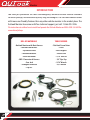
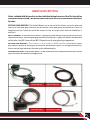
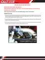
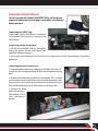
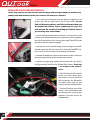
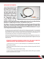
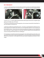
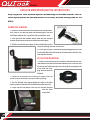
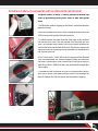
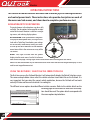
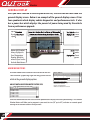
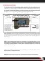
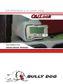
GM DURAMAX 6.6L 2001-2006
Part # 40366 v1.0.0
INSTALLATION MANUAL
®
Monitor
REMEMBER THIS IS A PERFORMANCE PRODUCT USE AT YOUR OWN RISK.
This product is not intended to be used to break the law.
Do not use this product until you have carefully read the following agreement. This agreement sets forth the terms and conditions for the use of this product. The installation of this product indicates that the buyer has read and understands this agreement
and accepts the terms and conditions. Never exceed recommended vehicle or tire top speed ratings.
DISCLAIMER OF LIABILITY
Bully Dog Technologies, LLC. Its distributors, jobbers, and dealers (hereafter Seller) shall be in no way responsible for the
product’s proper use and service. THE BUYER HERBY WAIVES ALL LIABILITY CLAIMS.
The Buyer acknowledges that he is not relying on the Sellers skill or judgment to select or furnish goods suitable for any particular purpose and that there are no liabilities which extend beyond the description on the face hereof, and the Buyers hereby
waivers all remedies or liabilities expressed or implied, arising by law or otherwise, (including without any obligation of the
Seller with respect fitness, merchantability and consequential damages) or whether or not occasioned by the Seller’s negligence.
The Seller disclaims any warranty and expressly disclaims any liability for personal injury or damages. The Buyer acknowledges
and agrees that the disclaimer of any liability for personal injury is a material term for this agreement and the Buyer agrees to
indemnify the Seller and to hold the seller harmless from any claim related to the item of the equipment purchased. Under not
circumstances will the Seller be liable for any damages or expenses by reason of use or sale of any such equipment.
The Seller assumes no liability regarding the improper installation or misapplication of its products. It is the installer’s responsibility to check for proper installation and if in doubt contact the manufacturer.
The Buyer is solely responsible for all warranty issues from the manufacturer.
LIMITATION OF WARRANTY
BULLY DOG TECHNOLOGIES, LLC. (Hereafter “Seller”) gives Limited Warranty as to description, quality, merchantability, and
fitness for any particular purpose, productiveness, or any other matter of Seller’s product sold herewith. The Seller shall be in no
way responsible for the products proper use and service and the Buyer hereby waives all rights other than those expressly written
herein. This warranty shall not be extended, altered or varied except be a written instrument signed by Seller and Buyer.
The Warranty is Limited to one (1) year from the date of sale and limited solely to the parts contained within the products kit. All
products that are in question of Warranty must be returned prepaid to the Seller and must be accompanied by a dated proof of
purchase receipt. All Warranty claims are subject to approval by BULLY DOG TECHNOLOGIES, LLC.
Under no circumstances will the Seller be liable for any labor charged or travel time incurred in diagnosis for defects, removal, or
reinstallation of this product or any other contingent expenses.
Under no circumstances will the Seller be liable for any damage or expenses incurred by reason of the use or sale of any such
equipment.
IN THE EVENT THAT THE BUYER DOES NOT AGREE WITH THIS AGREEMENT: THE BUYER MAY PROMPTLY RETURN THIS PRODUCT,
IN A NEW AND UNUSED CONDITION, WITH A DATED PROOF OF PURCHASE TO THE PLACE OF PURCHASE WITHIN TEN (10) DAYS
FROM DATE OF PURCHASE FOR A FULL REFUND.
THE INSTALLATION OF THIS PRODUCT INDICATES THAT THE BUYER HAS READ AND UNDERSTANDS THIS AGREEMENT AND
ACCEPTS ITS TERMS AND CONDITIONS.
1
TABLE OF CONTENTS
INTRODUCTION ............................................................................................ PAGE 3
BILL OF MATERIAL ........................................................................................ PAGE 3
HARNESS DESCRIPTIONS .............................................................................. PAGE 4
OUTLOOK INSTALLATION........................................................................ PAGES 5-12
Sub-Harness Install ......................................................................................................page 5
OBD 2 Harness Install ...................................................................................................page 6
Main Harness Install.....................................................................................................page 7
Pyrometer Installation ............................................................................................page 8-10
Mounting Options ................................................................................................. page 11-12
OPERATING INSTRUCTIONS .................................................................... PAGE 13-20
Navigation/Joystick Operation .................................................................................... page 13
Using the OutLook / Selecting the Correct Vehicle................................................. pages 13-14
Vehicle Selection Details ............................................................................................ page 14
General Display .......................................................................................................... page 15
Main menu / Menu Items ...................................................................................... page 15-17
OutLook Display Options ......................................................................................pages 18-20
2
Monitor
INTRODUCTION
You have just purchased the most technologically advanced Vehicle Monitor available
for diesel pickups, manufactured by Bully Dog Technologies. The OutLook Monitor comes
with more user friendly features than any other vehicle monitor in the market place. The
OutLook Monitor also comes with free technical support, just call: 1-866-285-5936.
The instruction set outlines how to install and operate the OutLook Monitor on 2003-2006 6.6L GM Duramax diesel pickups.
3
BILL OF MATERIALS
TOOLS NEEDED
• OutLook Monitor with Main Harness
• OutLook Sub Harness
• Pyrometer Probe
• Windshield Mount
• Pillar Pod Mount
• OBD 2 Connector & Harness
• Fuse Jack
• 90 degree connector
• Zip Ties
• Flat Head Screw Driver
• Pliers
• Wire Strippers
• Electric Drill
• 5/16” Drill Bit
• 1/8” Pipe Tap
• 9/16” Wrench
• 5/8” Wrench
HARNESS DESCRIPTIONS
Notice: included with this product are four individual wiring harnesses. Read the description
of each the harness below , the installation instructions will refer to the different harnesses
by name.
OUTLOOK MAIN HARNESS: The OutLook Monitor sits on one end of this harness and on the other end
notice it has two green plugs (one male and one female). These green plugs will connect this harness to
two other harnesses. Further the end of this harness has two sets of pyro wires which are labeled Pyro 1
and Pyro 2
OBD 2 HARNESS: On one end of this harness is a green plug (male) identical to the plug on the end of the
OutLook Main Harness. From that green plug two wires branch off, one is a yellow wire which is the Power Wire
and the other is the OBD 2 wire with the OBD 2 Plug on the end (a rectangular plug in appearance).
OUTLOOK SUB-HARNESS: This harness is not used on 2006 vehicles. On one end is a green
plug (female) identical to the plug on the end of the OutLook Main Harness. On the opposite end of this
harness are two large connectors that make up the information plug.
PYROMETER PROBE: The pyrometer probe is a steel braded cable with a probe on one end and a red and
yellow electronic connection on the opposite end.
Sub-Harness
OBD 2 Harness
OutLook Main
Pyrometer Probe
4
Monitor
INSTALLATION INSTRUCTIONS
INSTALLING THE OUTLOOK SUB-HARNESS
Skip this step if installing on a 2006 vehicle. The OutLook Sub-Harness is not used during
installation on a 2006 vehicle.
In this step you will connect the Information plug to 2003-2005 vehicles.
INFORMATION PLUG:
1. Disconnect the stock information plug from the stock information plug receiver. The plug is located on the driver
side of the engine bay on top of the engine. To disconnect, gently press the lever ears in and pull back on the
lever. The plugs should disconnect smooth and easily.
2. Plug the OutLook information plug into the stock information plug receiver and plug the stock information plug
into the OutLook information plug receiver.
3. Run the green connector (female) on the end of the OutLook Sub-Harness over to the back corner of the engine
bay on the drivers side and let it sit while installing the other harnesses.
5
INSTALLING THE OBD 2 HARNESS
In this step you will connect the OBD 2 Plug, run the green
connector and power wire through the firewall, and connect
the power wire.
Connecting the OBD 2 Plug:
Plug the OBD 2 Harness into the OBD 2 Plug located
on the bottom side of the dash on the drivers side
of the vehicle.
Green Plug through the firewall:
1. Run the end of the OBD 2 Harness (green plug)
through the firewall, pull the yellow power wire
completely through the firewall.
2. Set the green male connector in the back corner of the engine bay and leave it while hooking up the yellow
power wire.
Connecting the yellow Power wire:
1. Prepare the yellow power wire by stripping the end of the wire about .25”.
Connect the blue 90 degree connector to the end of the power wire using
pliers.
2. Remove the fuse box cover and locate the fuse labeled “ING E.”, remove
the fuse and place the fuse jack along with the fuse back into position. Make
sure that the fuse jack is placed on the dead side of the fuse to ensure that
the OutLook Monitor only turns on when the key is in the on position.
3. Connect the yellow
power wire to the fuse
jack attached to fuse
“ING E” and close the
fuse box.
6
Monitor
INSTALLING THE OUTLOOK MAIN HARNESS:
In this step you will run the OutLook harness plugs and wiring through the firewall and
connect the Main Harness to the Sub-Harness and the OBD 2 Harness.
1. For a clean install first peel back the weather stripping on the
driver’s side door seal right next to the dash and down. See the
OutLook Mounting options available to determine how you
will mount the OutLook before completing this step; this
will save you the trouble of installing the OutLook twice if
you are using an A-Pillar mount.
2. Set the OutLook Monitor up on the driver’s side dash and run the
OutLook wires down behind the dash to conceal the wiring Remove
the side dash panel to assist in running the wiring. Reinstall the side
dash panel and the weather stripping.
3. Run the end of the OutLook wiring harness through the firewall
into the engine bay. Use the same hole as done with the OBD 2 Harness. Pull all of the slack from the cab through the firewall.
4. Connect the green plug (male) on the end of the OBD 2 Harness to
the green plug (female) on the OutLook Main Harness.
5. Connect the green plug (female) on the end of the Sub-Harness
to the green plug (male) on the OutLook Main Harness. Omit step
5 for installs on all 2006 vehicles.
6. Go inside the cab of the vehicle
to test the install before going
any further. Turn the ignition to
the run position, the OutLook at
this point should light up and
display a vehicle selection screen.
2006 wiring will NOT have a Sub-Harness connection
7
7. Secure all wiring to ensure that
wiring is safe from extreme heat
and moving parts using zip ties
provided. (save two zip ties for
the pyrometer)
INSTALLING THE PYROMETER:
In this installation section you
will tap and mount the pyrometer probe into the exhaust
either pre-turbo or post turbo
and then connect the end of
the pyrometer to the OutLook
Main Harness. Doing so will
allow you to monitor Exhaust
Gas Temperatures which is
a very important diagnostic
measure. Exhaust Gas Temperatures indicate how hot the motor is getting and can be used to set safety defueling
parameters (see operating instructions “Set Pyrometer Defuel Level”).
Post Turbo vs. Pre-turbo: You may decide between mounting the pyro either post turbo
or pre-turbo. The difference in location determines what temperatures will read on your
OutLook. Pre-turbo mounting is recommended on the GM Duramax because it is easy to
install and provides accurate, safe readings.
The option does exist to mount both a Pre-turbo and a Post-turbo pyrometer probe. It is recommended
that two pyrometers be used if a vehicle is running more that 50 horsepower over stock. On the OutLook
display screen Pyro 1 temps are constantly shown in the bottom left quadrant (If you mount pyro 1 in a
post turbo location, the numbers in that quadrant will represent post turbo).
Whether you mount post turbo or pre-turbo you need to monitor your temperatures; know what is
safe and when to back off. Use the pyrometer calibration procedure below to figure out what your
safety limits are.
PYROMETER CALIBRATION PROCEDURE: BEFORE THIS STEP CAN BE COMPLETED
COMPLETELY INSTALL THE OUTLOOK AND ALL OF ITS COMPONENTS.
1. Vehicle must be set to STOCK HP/TQ levels-meaning no HP/TQ modifications of any kind (downloader or plug-in modules).
2. Engine must be put under full load for as long as possible on the hottest day possible. Pull a hill
or pull a trailer.
3. During a heavy load pull, record the highest reading.
4. Take that reading and add 150 degrees to the high number and that will be your new defuel
number that you do not want to exceed.
8
Monitor
POST TURBO MOUNT:
1. Find a location on the exhaust pipe that is 3-6”downstream from the turbo charge output. Then drill a 5/16”hole
and run a 1/8” pipe tap into the hole. Mount the pyrometer probe in the hole , use a 9/16” wrench to tighten the
probe holder or tube fitting to the down tube. Then tighten the pyro probe cap to the holder using a 5/8” wrench.
2. Run the pyro cable along the brim of the engine bay so the end meets the end of the OutLook Main Harness and use zip ties to secure the line.
3. Connect the Pyrometer end to the OutLook Main Harness: if you want post turbo temperatures displayed in
the bottom left quadrant on the Outllook screen connect the post turbo connectors to the Pyro 1 connectors on
the OutLook Main Harness. Connect the shorter wire from the pyrometer to the longer wire on the OutLook Main
Harness labeled pyro 1 using a set of pliers and a screw driver. Connect the longer wire from the pyrometer to the
shorter wire coming off the OutLook Main Harness labeled pyro 1.
4. If a second pyro is not used then connect the remaining pyro 2 wires to the long black ground wire that is sticking out from the Main Harness using the existing hardware. This will ensure that there is no electrical interference
between the Pyro connections. To further protect the connections wrap all of the pyrometer connections in electrical tape.
9
PRE-TURBO MOUNT:
1. Drill a 5/16” hole into the exhaust manifold where all the exhaust runners of the manifold come together
just before the turbo exhaust inlet. Then tap the hole with a 1/8: pipe tap and mount the pyrometer probe
in the hole. Use 9/16” wrench to tighten the probe holder or tube fitting to the down tube. Then tighten the pyro
probe cap to the holder using a 5/8” wrench.
2. Run the pyro cable along the brim of the engine bay so the end meets the end of the OutLook Main Harness and use zip ties to secure the line.
3.Connect the Pyrometer to the OutLook Main Harness: if you want Pre-Turbo temperatures displayed in the bottom left quadrant on the Outllook screen connect the Pre-Turbo pyrometer connectors to Pyro 1 connectors on
the OutLook Main Harness. Connect the shorter wire from the pyrometer to the longer wire on the OutLook Main
Harness labeled pyro 1 using a set of pliers and a screw driver. Connect the longer wire from the pyrometer to the
shorter wire coming off the OutLook Main Harness labeled pyro 1.
4. If a second pyro is not used then connect the remaining pyro 2 wires to the long black ground wire that is sticking out from the Main Harness using the existing hardware. This will ensure that there is no electrical interference
between the Pyro connections. To further protect the connections wrap all of the pyrometer connections in electrical tape.
10
Monitor
OUTLOOK MONITOR MOUNTING INSTRUCTIONS
Bully Dog offers three different options for mounting the OutLook Monitor. Each location option places the OutLook Monitor in an easily accessed viewing area for the
driver.
WINDSHIELD MOUNT:
1. Locate the windshield mount included with the OutLook Monitor as seen in. This does not come with mounting glue. Glue that
will adhere metal to glass can be found at any hardware store.
2. Place glue onto the window mount piece with the OutLook
Monitor holder detached from the windshield mount piece.
3. Hold the windshield mount piece on the windshield just to the
left of the steering wheel for one minute.
4. Let the glue set up as instructed by glue packaging and then slide
the OutLook Monitor holder onto the window mount with the OutLook Monitor attached.
PILLAR POD MOUNTING:
1. Locate the OutLook Pod Mount Circle that is included with the OutLook Monitor and attach the OutLook Monitor to the Pillar Pod Circle
by running the OutLook wiring harness through the rectangular hole
in the circle and snapping the back onto the
OutLook.
2. Follow the instructions for installing the single Pillar Pod
mount that are included in the pillar mount package.
3. Run the OutLook wires down through the hole in the pillar
mount system and connect the OutLook to the other harnesses.
4. Finally slide the Pod Mount Circle with the OutLook attached
into the pillar
mount hole.
11
OUTLOOK CUSTOM A-PILLAR MOUNT (NOT INCLUDED WITH THE OUTLOOK)
The pillar comes in black, it can be painted to match any
color by purchasing OEM paint color at any auto paint
store.
1. Pull Back the weather stripping on the driver’s side of the vehicle to
prepare the install.
2. Run the OutLook Main Harness wires through the front end of the
A-Pillar mount and snap the OutLook into place.
3. Carefully remove the paper from the sticky tape on the inside of
the OutLook Pillar Pod. Place the OutLook Pillar Pod over the OEM
pillar. The OutLook Main Harness wire will run down between the
pod and the pillar into the back of the dash. Put pressure against the
tape areas to ensure a good connection between the stock pillar and
the OutLook Pillar Pod.
4. Drill 1 hole with a 13/64 drill bit on the top part of the OutLook
Pillar Pod underneath the weather stripping facing the outside of
the driver’s side window. Place a plastic rivet in the hole to ensure a
good fit and finish. Additional holes may be drilled if the pod does
not fit tightly.
5. Remove the side dash panel to access the OutLook Main Harness
wire, pull all of the slack down through the dash and through the
firewall. Replace the side dash panel and the weather stripping.
12
Monitor
OPERATING INSTRUCTIONS
This section of the instructions describes how to use the joystick to navigate menus
and control power levels. These instructions also provide descriptions on each of
the menus and sub-menus, and shows how to complete a performance test.
NAVIGATION/JOYSTICK OPERATION
The joystick moves in four directions: up, down, left,
and right. The descriptions below provide an explanation of what each direction is used for in navigating menus, and selecting display options.
UP AND DOWN: Scroll up and down in the general display to control power levels, If using the OutLook with a Triple Dog Downloader, your settings
will be Extreme, Performance, Towing and Stock.
Use the up and down directions to scroll between
menu items while in the main menu or any of the
sub-menus.
RIGHT: Press right to move from the general
display into the main menu. See the list of menu
items on the next page. Pressing Right will also select menu items and navigate to sub-menus.
LEFT: Press left to move from any sub-menu back to the main menu and back into the general display. It is also
used to reset any performance test.
USING THE OUTLOOK / SELECTING THE CORRECT VEHICLE
The first time you use the OutLook Monitor it will automatically display the Vehicle Selection screen.
The screen example below shows what the vehicle selection screen looks like on the OutLook. It is
very important that you select the correct vehicle application, because the OutLook will not work
correctly if it does not know what vehicle it is working on.
The different screen options describe different vehicle scenarios. Refer to the vehicle details on the
following page for clarification on when each vehicle opChoose Your Vehicle
tion should be used. The option details correspond with
03-06 6.0L Ford w/ BD Mod
03-06 6.0L Ford w/ other
the screen options top to bottom.
03-06 6.0L Ford w/TriDog
99.5-03 7.3L Ford w/ other
01-05 GM w /BD Module only
01-05 GM w / other or stock
01-05 GM w /TriDog
03-04 Dodge w/ BD Module
03-04 Dodge w / other
13
VEHICLE SELECTION DETAILS: The list below provides a description of vehicle type and product compatibility . Use this list to help correctly select vehicle and product type. The OutLook will not work
properly if you have selected the wrong vehicle and product combination.
On-the-fly power adjustments and set defuel levels are activated on selections highlighted in red
• 03-06 6.0L FORD W/BD MOD:
Used if you have a 2003-2006 6.0L ford Power Stroke along with a Bully Dog Rapid Power or Dyno Dominator
plug in module, a Power Pup Downloader, or stock
• 03-06 6.0L FORD W/ TRI DOG:
Used if you have a 2003-2006 6.0L Ford Power Stroke along with Triple Dog Downloader.
• 99.5-03 7.3L FORD W/OTHER:
Used if you have a 1999.5-2003 7.3L Ford Power Stroke
• 2006 GM DURAMAX:
Used if you have a 2006 Duramax with a Power Pup Downloader or Stock.
• 01-05 GM W/BULLY DOG MODULE ONLY:
Used if you have a 6.6L GM Duramax along with a Bully Dog Rapid Power or Dyno Dominator plug in module.
• 01-05 GM W/ OTHER OR STOCK:
Used if you have a 6.6L GM Duramax along with a competitors products, a Bully Dog downloader, or stock.
• 01-05 GM W/ TRI DOG:
Used if you have a 2001 or newer 6.6L GM Duramax along with Triple Dog Downloader.
• 06 DODGE W/OTHER:
Used if you have a 2006 Dodge Cummins in combination with a Power Pup Downloader, or stock.
• 06 DODGE W/TRI DOG:
Used if you have a 2006 Dodge Cummins in combination with a Triple Dog Downloader.
• 03-05 DODGE W/BD MODULE:
Used if you have a 2003-2005 Dodge Cummins with a Bully Dog Rapid Power or Dyno Dominator module.
• 03-05 DODGE W/OTHER:
Used if you have a 2003-2005 dodge Cummins with a competitors product, a Bully Dog Downloader, a Bully
Dog Torque Dog, or stock.
• 03-05 DODGE W/ TRI DOG DOWNLOADER:
Used if you have a 2003-2005 Dodge Cummins with a Bully Dog Triple Dog Downloader.
• 01 - 02 DODGE W/OTHER:
Used if you have a 2001-2002 Dodge Cummins
• 98.5 - 2000 DODGE W/OTHER:
Used if you have a 1999.5-2000 Dodge Cummins
14
Monitor
GENERAL DISPLAY
Once you have selected a vehicle upon initial use, the OutLook will then load the
general display screen. Below is an example of the general display screen. It has
four quadrants which display vehicle diagnostics and performance tests. It also
has a power bar which displays the percent of power being used by the vehicle
from a performance upgrade.
Top Left Quadrant
Displays User Preset
Options
Power Bar Displays the % of Power of Aftermarket
Performance Product Being Used by the Vehicle
Bottom Left Quadrant
Always Displays the
Pyro1 Temperature
Reading, Which Correlates to Pyro 1 on the
OutLook Main Harness.
Top Right Quadrant
Displays User Preset
Options
Bottom Right
Quadrant
Displays User Preset
Options
MAIN MENU ITEMS
All main menu items listed can be accessed on the OutLook Monitor by pressing right on the joystick button
while in the general display options.
ADJUST OUTLOOK SPEEDOMETER TO TIRE SIZE:
Adj Speedmtr to Tire Size
Main Menu
Adj Speedmtr to Tire Size
Set Top Left Display
Set Bottom Right Display
Set Pyro Defuel Level
View Last Ten Readings
View All-time Highs
View Current Settings
View Peak Values
Clear Saved Peaks
Vehicle Selection Screen
28.00 inches
28.25 inches
28.50 inches
28.75 inches
29.00 inches
29.25 inches
29.50 inches
Oversized aftermarket tires will cause the OEM speedometer to display inaccurate speed readings. This OutLook
Monitor feature will allow you to program in your exact tire size (28” up to 44”) and view an accurate speed
reading on the OutLook screen in miles per hour.
15
TOP LEFT DISPLAY: Select this to enter a sub-menu with a list of OutLook Display Options that you select to
view in the top left display quadrant of the OutLook screen. All of the OutLook Display Options are listed in this
instruction set with options specific to this make, model, and year of vehicle.
TOP RIGHT DISPLAY: Select this to enter a sub-menu with a list of OutLook Display Options that you can select
to view in the top right display quadrant of the OutLook Screen. All of the OutLook Display Options are listed in
this instruction set with option specific to this make, model, and year of vehicle.
BOTTOM RIGHT DISPLAY: Select this to enter a sub-menu with a list of OutLook Display Options that you can
select to view in the bottom right display quadrant of the OutLook screen. All of the OutLook Display Options are
listed in this instruction set with options specific to this make, model, and year of vehicle.
LIST OF DISPLAY OPTION: All featured list items can be displayed in Top Left, Top Right and Bottom Right quadrants
of the general display screen.
BOOST PRESSURE (PSI)
0-60 TIME IN MPH
PYRO 1 (F)
1/4 MILE TIME SPEED (MPH)
PYRO 2 (F)
PEAK BOOST PRESSURE
SPEED (MPH)
PEAK PYRO (EITHER CHANNEL)
ENGINE RPM
PEAK HORSEPOWER
TRANSMISSION SLIP
PEAK TORQUE
SLIP POWER REDUCTION
FASTEST 0-60 TIME
COOLANT TEMPERATURE
FASTEST 1⁄4 MILE TIME
HORSEPOWER AND TORQUE
SET PYROMETER DEFUEL LEVEL: Within this menu option Set Pyrometer Defuel Level
900º
is a list of Fahrenheit temperatures ranging from 900˚F up to 950º
1700˚F. Based upon where you have installed the pyrometer 1000º
1050º
probe (see installing the Pyro instructions) you will use this 1100º
1150º
option to select the highest temperature you ever want your 1200º
exhaust gas to reach. We recommend that you use our Pyrometer Calibration Procedure to find out what your pyrometer defuel level will be. Once a defuel level is put in
place if the EGT’s reach a level greater than or equal to the set level the OutLook will automatically lower the
horsepower and in turn bring EGT’s back down to a safe level. This feature has been designed to save the integrity of an engine by preventing unsafe engine temperatures. SEE VEHICLE SELECTION DETAILS FOR VEHICLE
AVAILABILITY.
The default defuel level temperature is 1200˚F. If you do not have a pyrometer hooked up to the OutLook it acts as though your EGT’s are 73° F and this safety feature will not work. Therefore your engine
is susceptible to overheating with the addition of performance upgrades.
16
Monitor
VIEW LAST 10 READINGS: This feature lets you view the
last pyro readings taken per key cycle, the last 10 pyro readings taken per key cycle, the last 10 boost readings per key
cycle, and if the features are available to your vehicle it will
show you your last 10 quarter mile runs and 0-60 runs. You
can also erase the last ten readings.
VIEW ALL TIME HIGHS: Select this and then choose to see
your five all time best 0-60 times and quarter mile times.
You can also choose to erase your all time highs to make
room for new ones.
VIEW CURRENT SETTING: This feature allows you to see
how the OutLook has been set up to work with the vehicle.
It will display what truck type was selected, what the tire
size was set to and what the emergency defuel level is set
to. This makes it simple to make sure you have these standards set up correctly.
VIEW PEAK VALUES: This feature will show you what all
of the single all time highs are for your vehicle on a single
screen.
View Last 10 Readings
Quarter Mile Times
0-60 Times
Peak Boost / Start Cycle
Peak Pyro / Start Cycle
Clear Top Ten Values
View All-time Highs
Quarter Mile Times
0-60 Times
Clear Top Ten Values
CURRENT SETTINGS
Truck Selected:
03-05 6.0L Ford w / BD Mod
Tire Size:
32 Inches
Emergency Power Cutoff :
1250˚F
CURRENT PEAKS
Boost:
Pyrometer:
Horsepower
Torque:
0-60 Time:
1/4 Mile Time:
0 PSI
000˚ F
0.0 HP
0.0 ft-lbs
0.00 Seconds
0.00 Seconds
CLEAR PEAK VALUES: This will enable you to erase the
peak values that are saved in the OutLook and displayed
when you select the View Peak Values main menu option.
Clearing the peak values will free up the OutLook to record
new values lower than the previously saved peaks.
VEHICLE SELECTION SCREEN: This is the same screen that
appears when the OutLook gets installed for the first time.
Use this feature if the wrong setting is set or if the OutLook
is transferred to a different brand of vehicle.
17
Choose Your Vehicle
03-05 6.0 L Ford w/ BD Mod
03-05 6.0L Ford w/ other
99.5-03 7.3L Ford w/ other
01-05 GM w /BD Module only
01-05 GM w / other or stock
03-05 Dodge w/ BD Module
03-05 Dodge w / other
OUTLOOK DISPLAY OPTIONS
The list below is all of the OutLook display options applicable to this make, model and year of
vehicle. Once you select to display one of the options below it will be displayed either in the top
left, top right, or bottom right quadrant of the OutLook Monitor screen. Navigate to these items
through the main menu by selecting either top right, bottom right or top left.
Top Left Quadrant
Displays User Preset
Options
Bottom Left Quadrant
Always Displays the
Pyro1 Temperature
Reading, Which Correlates to Pyro 1 on the
OutLook Main Harness.
Power Bar Displays the % of Power of Aftermarket
Performance Product Being Used by the Vehicle
Top Right Quadrant
Displays User Preset
Options
Bottom Right
Quadrant
Displays User Preset
Options
BOOST PRESSURE: A measure of air pressure generated by the turbo that is being forced into the engine
cylinder. Knowing the pressure will indicate how much stress is being put on the turbo and the engine itself.
On a stock pickup at high acceleration a turbo will generate 18 to 40 lbs. of boost depending upon year &
make of vehicle.
PYRO 1: Reads the signal received from the Pyro 1 connection on the OutLook Main Harness. Use this
feature to display EGT readings on the screen, also use this to get a recommended defuel reading using
the Pyrometer Calibration Procedure. This display option is permanently displayed in the bottom left
quadrant of the OutLook Screen.
PYRO 2: Reads the signal received from the Pyro 2 connection on the OutLook Main Harness. Use this
feature to display EGT readings on the screen.
SPEED: Vehicle rate of travel in Miles Per Hour. This feature does not change the OEM speedometer.
18
Monitor
RPM: Number of Crank Revolutions Per Minute
TRANSMISSION SLIP: Shows the % difference between transmission input shaft speed and output
shaft . Tells you in an easy-to-read % how much your transmission is slipping.
SLIP POWER REDUCTION: The % that engine power is reduced by a Bully Dog Module, using Tranny
Smart Software, to account for transmission slippage. Only available with a Bully Dog Rapid Power or
Dyno Dominator Module.
COOLANT TEMP: Temperature of vehicle coolant
HORSE POWER AND TORQUE: Measures engine output to the ground. Due to all of the factors involved
in actual driving, the number calculated by the OutLook may not match those derived from an actual
dynamometer.
0-60 TIME IN MPH: This is a performance test that displays and records how long it takes the vehicle to
go from a stand still at zero miles per hour to sixty miles Per Hour. This is a standard test that automobile
manufacturers often use to describe the low end performance of an automobile. To operate this function
simply follow the instructions displayed on the screen in one of the three quadrants chosen to display
this performance test. When bad starts occur and the test must be restarted, simply press left on the
OutLook Joystick and the performance test will restart itself and also refresh the screen instructions.
19
1⁄4 MILE TIME: This performance test will display and record how long it takes the vehicle to travel .25
miles from a complete stand still and how fast the vehicle was traveling at the exact point of completion.
If for some reason the test must be restarted simply press left on the OutLook Joystick and the performance test will restart itself and also refresh the screen instructions.
PEAK BOOST PRESSURE: Highest intake pressure in PSI ever recorded in that vehicle.
PEAK PYRO: Highest exhaust gas temperature ever reached; with regard to the location of the pyro,
whether the pyro is installed pre or post turbo.
PEAK HORSEPOWER: Highest horsepower ever reached.
PEAK TORQUE: Highest torque ever reached.
FASTEST 0-60: Best ever 0-60 time.
FASTEST 1⁄4 MILE TIME: Best ever 1⁄4 mile time.
20
Monitor
21
22
Downloaders
Intake Systems
Exhaust Systems
Performance Modules
See More at: bullydog.com
®
For Free Technical Support
Call: 866-bullydog (866-285-5936)