1
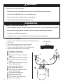
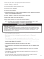
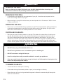
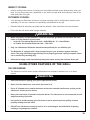
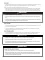
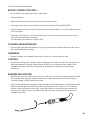
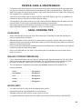
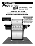
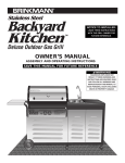
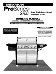
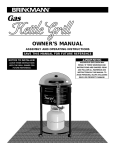
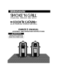
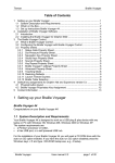
NOTICE TO INSTALLER:
LEAVE THESE INSTRUCTIONS
WITH THE GRILL OWNER FOR
FUTURE REFERENCE.
OWNER’S MANUAL
ASSEMBLY AND OPERATING INSTRUCTIONS
SAVE THIS MANUAL FOR FUTURE REFERENCE
WARNING
0
400 45
0
350
5
00
600 6
550
50
0
15
200 250
30
HAZARDOUS EXPLOSION MAY
RESULT IF THESE WARNINGS AND
INSTRUCTIONS ARE IGNORED. READ
AND FOLLOW ALL WARNINGS AND
INSTRUCTIONS IN THIS MANUAL TO
AVOID PERSONAL INJURY, INCLUDING
DEATH OR PROPERTY DAMAGE.
0
70
10
0
IMPORTANT SAFETY
WARNINGS
WE WANT YOU TO ASSEMBLE AND USE YOUR GRILL AS SAFELY AS POSSIBLE.
THE PURPOSE OF THIS SAFETY ALERT SYMBOL
IS TO ATTRACT YOUR
ATTENTION TO POSSIBLE HAZARDS AS YOU ASSEMBLE AND USE YOUR GRILL.
WHEN YOU SEE THE SAFETY ALERT SYMBOL
PAY CLOSE ATTENTION TO THE INFORMATION WHICH FOLLOWS!
READ ALL SAFETY WARNINGS AND INSTRUCTIONS CAREFULLY
BEFORE ASSEMBLING AND OPERATING YOUR GRILL.
DANGER
FOR YOUR SAFETY:
IF YOU SMELL GAS:
1. Shut off gas to the appliance at the LP cylinder and burners.
2. Extinguish any open flame.
3. Open the Lid.
4. If odor continues, leave the area and immediately call your gas supplier or your fire department.
WARNING
FOR YOUR SAFETY:
1. DO NOT store or use gasoline or other liquids with flammable vapors in the vicinity of this or
any other appliance.
2. An LP cylinder not connected for use shall not be stored in the vicinity of this or any other
appliance to avoid the possibility of explosion.
WARNING
1
•
Never store a spare LP gas cylinder under or near this grill.
•
Never fill the cylinder beyond 80% full.
•
A fire causing death or serious injury may occur if the above is not followed exactly.
WARNING
•
Never use natural gas in a unit designed for liquid propane gas.
•
Never use charcoal briquets or lighter fluid in a gas grill.
•
Leak test all connections before first use, even if grill was purchased fully assembled and after
each tank refill.
•
Never check for leaks using a match or open flame.
CAUTION!
Strong odors, colds, sinus congestion, etc. may prevent the detection of
propane. Use caution and common sense when testing for leaks.
•
Always keep gasoline, paint thinner, or other flammable liquids or combustible materials away
from your gas grill.
•
Always check the grill prior to each use as indicated in the "Pre-Start Check List" section of this
manual.
•
Keep children and pets away from hot grill. DO NOT allow children to use or play near this grill.
•
DO NOT leave the grill unattended while in use.
•
DO NOT allow the gas hose to come in contact with hot surfaces.
•
DO NOT allow grease from drain hole to fall on hose or valve regulator assembly.
•
Keep any electrical supply cords away from water or heated surfaces.
•
Keep a fire extinguisher on hand acceptable for use with gas products. Refer to your local
authority to determine proper size and type.
•
Never place more than 15 pounds on the side burner. DO NOT lean on the side burner shelf.
•
For household use only. DO NOT use this grill for anything other than its intended purpose.
•
DO NOT use while under the influence of drugs or alcohol.
•
Grill is hot when in use. To avoid burns:
•
•
•
•
•
DO NOT attempt to move the grill.
Lock the wheels so the unit does not accidentally move.
Wear protective gloves or oven mitts.
DO NOT touch any hot grill surfaces.
DO NOT wear loose clothing or allow hair to come in contact with grill.
USE CAUTION AND COMMON SENSE WHEN OPERATING YOUR GAS GRILL.
FAILURE TO ADHERE TO THE SAFETY WARNINGS AND GUIDELINES IN THIS
MANUAL COULD RESULT IN SEVERE BODILY INJURY OR PROPERTY DAMAGE.
SAVE THIS MANUAL FOR FUTURE REFERENCE.
2
WARNING
•
FOR OUTDOOR USE ONLY. DO NOT operate indoors or in an enclosed area such as garage,
shed or breezeway.
•
Use your grill OUTDOORS in a well ventilated space away from dwellings or other buildings to
prevent dangers associated with gas accumulation and toxic vapors. We recommend your grill
be situated at least 10 feet from buildings.
•
Maintain a minimum clearance of 24 inches (60 cm) between all sides of grill and walls or other
combustible material.
•
DO NOT install in or on a recreational vehicle and/or boat.
INSTALLATION INFORMATION:
The installation of this appliance must be in accordance with:
All applicable local codes, or in the absence of local codes, either:
• National Fuel Gas Code,
• ANSI Z223.1 1988 or latest edition (USA)
• Natural Gas Installation Code: CAN/CGA B149.1 (Canada)
• Propane Installation Code: CAN/CGA B149.2 (Canada)
To check your local codes, see your local LP gas dealer or natural gas company.
This grill was not intended to be connected to a natural gas supply line.
WARNING
LP GAS CYLINDER (NOT SUPPLIED WITH THIS GRILL)
The LP (Liquid Propane) gas cylinder specifically designed to be used with this grill must have
a 20 lb. (9.1 kg) capacity incorporating a Type 1 cylinder valve and an over-filling protection
device (OPD).
•
DO NOT connect this grill to an existing #510 POL cylinder valve with Left Hand threads. The
Type 1 valve can be identified with the large external threads on the valve outlet.
•
DO NOT connect to a propane cylinder exceeding this capacity.
•
DO NOT connect to a cylinder that uses any other type of valve connection device.
CYLINDER SPECIFICATIONS:
When purchasing or exchanging a cylinder for your gas grill, it must be constructed and marked in
accordance with the specifications for LP gas cylinders of the U.S. Department of Transportation
(DOT) or the National Standard of Canada, CAN/CSA-B339 as applicable with a listed over-filling
prevention device (OPD).
3
The cylinder must also be equipped with:
•
A shut-off valve terminating in a Type 1 gas cylinder valve outlet.
•
A Type 1 valve that prevents gas flow until a positive seal is obtained.
•
An arrangement for vapor withdrawal.
•
A collar to protect the cylinder shut off valve.
•
A safety relief device having direct communication with the vapor space of the cylinder.
•
A listed over-filling prevention device (OPD).
WARNING
•
Turn off the cylinder valve when your grill is not in use.
•
Handle the tank with care.
•
Always secure the cylinder in an upright position.
•
Never connect an unregulated LP gas cylinder to your grill.
•
DO NOT expose LP gas cylinders to excessive heat or ignition sources.
•
DO NOT store a spare LP gas cylinder under or near your grill.
•
Allow only qualified LP gas dealers to fill or repair your LP gas cylinder.
•
DO NOT allow the cylinder to be filled beyond 80% capacity.
•
Read and follow all warnings and instructions that are on the cylinder and that accompany this
product.
DANGER
•
Never store a spare LP gas cylinder under or near your grill when in use. This could cause
excess pressure to be expelled through the vapor relief valve resulting in fire, explosion, or
severe personal injury including death.
NOTE: PROPANE GAS IS HEAVIER THAN AIR AND WILL COLLECT IN LOW AREAS.
PROPER VENTILATION IS EXTREMELY IMPORTANT.
•
DO NOT insert any foreign objects into the valve outlet. Damage to the back-check could
result. A damaged back-check can cause a leak, possibly resulting in explosion, fire, severe
bodily harm, or death.
4
WARNING
FILLING THE LP GAS CYLINDER:
•
Allow only qualified LP gas dealers to properly fill or repair your LP gas cylinder.
•
New tanks should be purged prior to filling; inform LP gas dealer if you are using a new tank.
•
DO NOT allow the cylinder to be filled beyond 80% capacity. Over-filled tanks can create a
dangerous condition. Over-filled tanks can build-up pressure and cause the relief valve to expel
propane gas vapors. The vapor is combustible and if it comes in contact with a spark source or
flame an explosion causing severe burns, bodily harm, or death could occur.
•
Always use a protective cylinder cap when grill is not connected to cylinder.
•
If you exchange a cylinder with a qualified exchange program, be sure the cylinder has
a Type 1 valve and an over-filling prevention device (OPD).
INSTALLING THE LP GAS CYLINDER ONTO THE GRILL:
1. Check that the cylinder valve is closed by turning the
knob clockwise.
2. Loosen the two (2) wing nuts on the tank clamp bracket
to allow the bracket to move up and down freely.
3. Place the cylinder onto the support bracket.
4. Orient the cylinder such that the valve opening faces
the front of the grill.
5. The tank clamp bracket should slide upward and hook
inside one of the openings on the top flange of the tank.
6. Fully tighten both wing nuts to secure the tank.
HOSE AND REGULATOR:
Your grill is equipped with a Type 1 connection device with the following features:
1. The system will not allow gas flow from the cylinder until a positive connection to the valve has been made.
NOTE: The cylinder valve must be turned off before any connection is made or removed.
2. A thermal device that will shut off the gas flow if the device is subject to temperatures above 240°F and
300°F (115°C and 150°C). If this should happen, remove the entire regulator assembly and throw it away.
A replacement regulator assembly can be purchased by contacting Brinkmann at 1-800-527-0717.
The cause of the excessive heat should be determined and corrected before using your grill again.
3. A flow limiting device, when activated, restricts the flow of gas to 10 cubic feet per hour.
5
WARNING
•
Never use your grill without leak testing all gas connections and hoses. See the section on
"Leak Testing" in this manual for proper procedures.
WARNING
The pressure regulator and hose assembly supplied with your gas grill is designed to work with an
LP gas supply cylinder.
•
DO NOT attempt to connect it to any other fuel supply source such as a natural gas line.
•
DO NOT use any other pressure regulator/hose assembly other than the one supplied with your grill.
•
DO NOT attempt to adjust or repair the regulator. A replacement regulator can be supplied by
contacting the manufacturer. The regulator is designed to operate at an output pressure of 11
inches of water column (2.74 kPa).
During assembly and/or replacement of the gas cylinder, keep the gas supply hose free of kinks and/or
damage.
Visually inspect the hose assembly prior to each use for evidence of damage, excess wear, or
deterioration. If found, replace the assembly before using your grill. Only the manufacturers supplied
replacement should be used.
WARNING
CONNECTING HOSE AND REGULATOR TO AN LP GAS CYLINDER
•
Insure the tank valve is CLOSED prior to connecting the LP gas cylinder to your grill. Turn the
valve knob clockwise to properly close the valve. Read and follow all instructions and warnings
on the supply hose safety tags. Read and follow all warnings in this manual concerning the safe
use of LP gas cylinders and the hose and regulator before connecting cylinder to grill. Read
and follow all warnings on the LP cylinder.
1. Check that the cylinder valve is closed by turning the knob clockwise.
2. Check that the grill’s burner knobs are in the proper OFF positions.
3. Remove the protective plastic cap from the cylinder valve and the connection device.
4. Insert the nipple of connection device into the valve outlet. Insure that the device is centered properly.
5. Turn the large coupling nut clockwise by hand and tighten to a full stop. Take care not to cross thread
the coupling nut onto the cylinder valve. Do not over-tighten the knob onto the valve. Do not use tools
to tighten connection.
NOTE: If you are unable to make the connection, repeat steps 4 and 5.
6. Check that the hose does not contain kinks, does not contact sharp edges, and does not contact
surfaces that may become hot during use.
7. Leak check all fittings before lighting your grill. See section on "Leak Testing" in this manual.
6
DANGER
LEAK TESTING:
To prevent fire or explosion hazard:
•
DO NOT smoke or permit ignition sources in the area while conducting a leak test.
•
Perform test OUTDOORS only in a well ventilated area.
•
Never perform a leak test with a match or open flame.
•
Never perform a leak test while the grill is in use.
WARNING
WHEN TO PERFORM A LEAK TEST:
•
After assembling your grill and before lighting for the first time, even if purchased fully assembled.
•
Every time the LP gas cylinder is refilled or if any of the gas components are replaced.
•
Any time your grill has been moved.
•
At least once per year or if your grill has not been used for more than 60 days.
CHECKING FOR LEAKS:
1.
2.
3.
4.
Create a mixture of 50% water and 50% liquid dishwashing soap.
Open the lid.
Insure all burner knobs are set to the OFF position.
Turn on the fuel supply at the LP cylinder valve.
Turn the cylinder valve knob one turn counterclockwise.
5. Apply the soap water mixture to the following:
7
A
Supply tank (cylinder) weld
B
Connection nut to tank valve.
C
Back side of connection nut to brass
nipple.
D
Brass nipple connection into regulator.
E
Regulator connections to gas supply
hoses.
F
Gas supply hose connection to main
burner valve assembly.
G
Main burner valve stem caps.
H
Main burner orifice fittings.
I
Gas supply hose connection to side
burner valve assembly.
J
Side burner valve stem cap.
K
Side burner orifice fitting.
L
The full length of gas supply hose
M
Tank valve to cylinder
Watch For Bubbles
G
F
J
K
I
H
L
E
M
D
C
B
A
6. Check each place listed (A -M) for growing bubbles which indicates a leak.
7. Turn OFF gas supply at cylinder valve.
8. Turn on control knobs to release gas pressure in hose.
9. Turn control knobs to “off” position.
10. Tighten any leaking connections.
11. Repeat soapy water test until no leaks are detected. DO NOT use the grill if leaks cannot be stopped.
Contact a qualified gas appliance repair service.
12. Turn OFF gas supply at cylinder valve until you are ready to use your grill.
13. Wash off soapy residue with cold water and towel dry.
14. Wait 5 minutes to allow all gas to evacuate the area before lighting grill.
NOTE: The leak test must be performed in an area that has adequate lighting in order to see if
bubbles are developing. DO NOT use a flashlight to check for bubbles.
WARNING
PRE-START CHECK LIST:
Property damage, bodily harm, severe burns, and death could result from failure to follow these
safety steps. These steps should be performed after the grill has been assembled, stored, moved,
cleaned, or repaired. DO NOT operate this grill until you have read and understand ALL of the
warnings and instructions in this manual.
•
Insure that the grill is properly assembled.
•
Check burner venturi tubes for blockage from insect nests. See section on "Cleaning and
Maintenance".
•
Check that all burner venturi are seated properly over the valve outlets as shown
in the assembly instructions. The orifice must be inside the burner venturi for proper air/fuel mixing.
•
Inspect the gas supply hose for burns, chaffing, kinks, and proper routing before each use. Hoses
should be at least 3 inches from hot surfaces.
•
Leak check all gas connections and hoses. See section on "Leak Testing".
•
Ensure that all electrical supply cords are properly grounded and are kept away from water and hot
surfaces.
•
Position your grill on level ground in a well ventilated location, a safe distance from combustible
materials and buildings.
•
Properly place an empty grease collection cup under the grease drain hole in the bottom of the
grill to catch grease during use.
•
Your grill is covered with a plastic film to protect the stainless steel finish during shipment and
assembly. This plastic film must be removed before operating your grill.
8
WARNING
Read, understand and follow all warnings and instructions contained in this manual. DO NOT skip
any of the warnings and instructions contained in the preceding sections of this manual.
WARNING
LIGHTING INSTRUCTIONS:
Follow the instructions exactly.
1. OPEN THE GRILL LID before attempting to light the burner so that fumes do not accumulate
inside the grill. An explosion could occur if grill lid is down.
2. Check that all burner control knobs and the cylinder valve are turned to the OFF position.
3. Turn on the fuel supply by rotating the cylinder valve knob counterclockwise to full open.
4. DO NOT stand with head, body, or arms over the grill when lighting.
LIGHTING THE MAIN BURNER:
1. Open lid before lighting.
2. Turn on either side of the burner by pressing in and rotating
the control knob to the HIGH position.
3. Press and hold the igniter button until the burner ignites.
4. If burner does not ignite immediately, turn the burner control
knob to OFF and wait 5 minutes for gas to evacuate the grill.
Repeat steps 1 through 4 until burner ignites.
5. If burner does not ignite using the push button igniter
wait 5 minutes, see "Match Lighting the Main Burner" section.
6. Once lit, the other side of the main burner can be lit
automatically by turning the other control knob to "HIGH".
MATCH LIGHTING THE MAIN BURNER:
1. Open lid before lighting.
2. Turn the burner control knobs to OFF.
3. Strike and place a long wooden match through the air holes in the bottom LEFT hand side of the grill
to approximately 1/2" (2 to 3 cm) from the burner.
4. Turn on the LEFT burner control knob to the HIGH position. The burner should light within 5 seconds.
5. If the burner does not light, turn the control knob to OFF and wait 5 minutes for gas to evacuate the
grill. Repeat steps 1 through 4 until the burner ignites.
6. Once lit, the other side of the main burner can be lit automatically by turning the other control knob to "HIGH".
7. If the burner does not light within the first few attempts of match lighting, there is a problem with the
gas supply. Turn off the gas at the burner and cylinder. DO NOT attempt to operate the grill until the
problem is found and corrected. See “Trouble Shooting” section of this manual.
9
LIGHTING THE SIDE BURNER:
1. Open or remove the lid to the side burner before lighting.
• O
OFF
2. Turn on the side burner by pressing in and rotating the
control knob to the HIGH position.
3. Press and hold the igniter button on the main control
panel until the burner ignites.
4. If burner does not ignite immediately, turn the burner
control knob to OFF and wait 5 minutes for gas to
evacuate the grill. Repeat steps 1 through 4 until
burner ignites.
5. If burner does not ignite using the push button igniter
wait 5 minutes, see "Match Lighting the Side Burner" section.
• Tu
bu
• If
tu
lig
HIGH
• R
lig
LOW
To Turn Knob On: Push dial in and turn
counter-clockwise.
• Tu
Ma
To Turn Knob Off: Turn dial clockwise until it
locks in "OFF" position.
MATCH LIGHTING THE SIDE BURNER:
1. Open or remove the lid to the side burner before lighting.
2. Turn the burner control knob to OFF.
3. Strike and place a long wooden match approximately 1/2" (2 to 3 cm) from the burner.
4. Turn the side burner control knob to the HIGH position. The burner should light immediately.
5. If burner does not ignite immediately, turn the burner control knob to OFF and wait 5 minutes for gas
to evacuate the grill. Repeat steps 1 through 4 until the burner ignites.
6. If the burner does not light within the first few attempts of match lighting, there is a problem with the
gas supply. Turn off the gas at the burner and cylinder. DO NOT attempt to operate the grill until the
problem is found and corrected. See “Trouble Shooting” section of this manual.
TURNING OFF THE GRILL:
1. Turn OFF the LP tank valve.
2. Turn all burner control knobs to the OFF position.
NOTE: Turn off LP cylinder first to prevent gas from being left in the system under pressure.
CAUTION!
•
The LP tank valve should always be in the off,
or closed, position when the grill is not in use.
To turn off the LP tank valve,
turn knob clockwise until it stops.
10
WARNING
OPERATING THE GRILL:
Never use Charcoal or Lighter Fluid inside your Gas Grill. Read and follow all warnings and
instructions contained in the preceding sections of this manual.
BREAKING IN YOUR GRILL:
•
In manufacturing and preserving the components of your grill, oil residue may be present on the
burner and cooking surfaces of your grill.
•
Before cooking on your grill for the first time you should operate it for 15 minutes on "HIGH" to burn
off these residual oils.
PREHEATING THE GRILL:
•
Prior to use, it is recommended that you preheat your grill. This ensures that the grilling surfaces are
at the desired temperatures to sear the food sugars when cooking. After lighting your grill, set the
main burner control knobs to the "HIGH" position for 10 to 15 minutes.
CONTROLLING FLARE-UPS:
•
Flare-ups are a part of cooking meats on a gas grill. This adds to the unique flavor of cooking on a
gas grill. Excessive flare-ups can over-cook your food and cause a dangerous situation for you or
your grill. Excessive flare-ups result from the build-up of grease in the bottom of your grill. If this
should occur, DO NOT pour water onto the flames. This can cause the grease to splatter and could
result in serious burns or bodily harm. When grease fires occur close the lid and turn off the main
burners until the grease burns out. Use caution when opening the lid as sudden flare-ups may occur.
WARNING
•
DO NOT leave your grill unattended while in use.
•
DO NOT move grill when in use. Lock wheels in place to stabilize grill.
•
DO NOT use water to extinguish flare-ups.
•
Have fire extinguisher readily accessible suitable for use with gas appliances.
•
Only use ceramic briquets that are large enough so they do not fall through the briquet grate to the
burner. This will prevent grease build-up.
TO MINIMIZE FLARE-UPS:
11
•
Trim excess fat from meats prior to cooking.
•
Cook meats with high fat contents (chicken or pork) on Low settings or indirectly.
•
Ensure that your grill is on level ground and the grease is allowed to evacuate the grill through the
drain hole in the bottom.
INDIRECT COOKING:
•
Indirect cooking is the process of cooking your food without the heat source being directly under your
food. You can sear meats over a high flame on one side of the grill while slow cooking a roast on the
other (unlit) side of the grill.
ROTISSERIE COOKING:
•
Your grill was pre-drilled from the factory to include mounting holes for a Brinkmann rotisserie (sold
separately). Do not use a rotisserie not specifically manufactured for this grill.
•
Read and follow all instructions provided with the rotisserie. Save instructions for future reference.
•
Do not use the side burner when using a rotisserie.
WARNING
•
When using an AC current rotisserie, it must be electrically grounded in accordance with local
codes, or in the absence of local codes:
• In the US: The National Electrical Code – ANSI-NFPA No. 70 – Latest Edition
• In Canada: the Canadian Electrical Code – CSA C22.1
•
Only use a Brinkmann Rotisserie manufactured specifically for use with this grill.
•
The Rotisserie is equipped with a three pronged plug for your protection against electrical
shock. This plug should be plugged directly into a properly grounded 3 prong receptacle. Never
cut or remove the grounding plug.
•
All electrical supply cords should be kept away from water and any hot surfaces of the grill.
USING OTHER FEATURES OF THE GRILL:
THE SIDE BURNER:
•
The side burner can be used to prepare side dishes such as beans, potatoes, corn, or to warm
sauces.
•
The burner valve can be adjusted from WARNING
high to low depending upon your cooking demands.
•
Read instructions on lighting your grill to light the side burner.
•
Never close the side burner cover when the burner is lit.
•
Use a 10" diameter pot or smaller that does not have an extended handle when cooking on the
side burner. Center pot over burner.
•
Never place more than 15 pounds on the side burner. The side burner is not constructed to hold
weight exceeding 15 pounds.
•
Use caution to avoid bumping grill, side burner or pot to prevent pot from spilling contents
possibly leading to severe burns.
•
DO NOT use side burner to deep fry food in oil to avoid dangers associated with oil igniting
creating a very dangerous situation.
12
THE SINK:
•
Attach a standard garden hose to the supply line and a spigot to provide water for the faucet. Turn on
the water supply to the garden hose. The faucet handle turns on and off the water flow.
NOTE: Do not leave water supply to garden hose on when not in use.
•
Attach the drain hose (provided) at the base of the sink to direct outflow water. A pail or large bucket
can be placed at the end of the drain hose to catch the waste water. If desired, a standard garden
hose can be attached to the drain hose to lengthen the drain hose and further evacuate waste water.
WARNING
•
DO NOT extinguish grease fires using water.
•
Use caution when turning on the faucet to not touch surface areas of grill as they may be very
hot.
•
Use caution when turning on the faucet so that water does not splash onto the side of the grill
lid or grill surface. Resulting steam can cause serious burns.
THE COOLER:
•
The cooler is designed to be removable from the grill. The cooler and lid are dishwasher safe. The lid
can be used as a cutting board.
•
It is not recommended to use the cutting board for meats when food or beverages may be stored
inside the cooler as meat juices will drip into cooler.
THE STORAGE AREA:
•
The storage area may be used to stow a grill cover or cooking utensils. The baskets located on the
back side of the doors can be utilized for holding condiments or grill cleaning supplies (tools).
WARNING
•
DO NOT store a spare LP gas cylinder (filled or empty) under or near the grill.
•
Never store flammable liquids or spray canisters under or near the grill.
•
The storage area may become wet from the sink drain, hose assemblies or rain. Do not store
items under the sink that would ruin if exposed to water.
WARNING
TRANSPORTING AND STORAGE:
13
•
Never move a grill when it is hot or when objects are on the cooking surfaces.
•
Make sure that cylinder valve is shut off. After moving the grill check that all gas connections
are free of leaks. Check the venturi tubes to ensure they are properly connected to the valves
and the orifices are inside the venturi tube.
Follow the instructions listed below.
BEFORE STORING YOUR GRILL:
•
Ensure that the fuel supply tank valve is fully closed.
•
Clean all surfaces.
•
Lightly coat the burners with cooking oil to prevent excess rusting.
•
If storing the grill indoors, disconnect the LP tank and leave the LP tank OUTDOORS.
•
Place a protective cap cover on the LP tank and store the tank outdoors in a well ventilated area out
of direct sunlight.
•
If storing the grill outdoors, cover the grill with a grill cover for protection from the weather. A grill
cover can be purchased by contacting:
The Brinkmann Corporation at 1-800-527-0717.
CLEANING AND MAINTENANCE:
•
For safe grilling and peak performance of your grill, perform these checks at least twice per year or
after extended periods of storage.
HARDWARE
•
Be sure to tighten up all hardware (nuts, bolts, screws, etc.) at least twice per year.
CASTINGS
•
Remove the cooking grids, ceramic briquets, and burner from inside your grill. Use a brush with hot
water and detergent to remove excess residue. NEVER use a commercial oven cleaner. Rinse
completely with water. Towel dry and replace all components as described in the assembly
instructions.
BURNERS AND VENTURIS
•
Although your burner is constructed of cast iron, it will rust as a result of the extreme heat and acids
from cooking foods. Regularly inspect the burner for cracks, abnormal holes, and other signs of
corrosion damage. If found, replace the burner.
•
Venturi tubes can become blocked by spiders and other insects building their nests. Blocked venturi
tubes can prevent gas flow to the burner and could possibly result in a venturi fire. To clean the
venturis, remove the burner from the grill. Use a pipe cleaner or a small wire and insert into the
opening of the venturi. Remove any obstructions that may exist. Replace the burner as per the
assembly instructions.
14
COOKING GRILLS
•
Clean with mild soap detergent and water. A brass bristled brush or a nylon cleaning pad can be used
to remove residue from the cast iron cooking surface. Do not use steel wire bristles to clean the cast
iron cooking grills. Steel can cause the finish to chip or crack. DO NOT use a commercial oven
cleaner.
CERAMIC BRIQUETS
•
Periodically, it may be necessary to inspect and clean the ceramic briquets to prevent excess grease
build-up. When the grill is cold, remove the cooking grills. Inspect each briquet and replace briquets that
are broken, chipped or damaged to the extent that it may fall through the briquet grate and onto the
burner. Replace the cooking grills and light the main burner. Operate the grill on "HIGH" for 10 minutes
to remove the excess grease. If purchasing replacement ceramic briquets, purchase only large briquets
that will not fall through the briquet grate as grease build-up on the briquets could result in grease fire.
•
Always make sure that the ceramic briquets are laying flat side down on the briquet grate.
TROUBLE SHOOTING:
Problem:
15
Possible Causes:
•
Burner will not light
1. Check LP cylinder fuel level.
2. Bad electrode spark.
Check to see if the grill will match light.
Electrode or collector may need adjustment.
3. Venturi may not be properly seated.
4. Venturi may be obstructed.
5. The cylinder valve may be closed.
6. Regulator is not properly seated on cylinder valve.
•
Fire at control knobs
1. Venturi is obstructed. See section on
Cleaning and Maintenance of the Venturi.
2. Venturi is improperly seated on control valve.
3. Gas connections may be loose.
Leak Check and tighten all connections.
•
Yellow Flames at burner
1. Venturi is obstructed. See section on
Cleaning and Maintenance of the Venturi.
•
Flame blows out on "LOW"
1. Venturi may be obstructed. See section on
Cleaning and Maintenance of the Venturi.
2. Grill is not sufficiently preheated.
3. Venturi is improperly seated on control valve.
•
Burner does not get hot enough
1. Flow control device has been activated in regulator.
2. Turn off the grill and the fuel supply. Disconnect the
grill from the cylinder valve. Reconnect the grill to
the cylinder and light grill. See section on
Connection to the LP Cylinder.
•
Grill is Too Hot
1. Excess grease build-up causing grease fires.
2. Damaged or faulty regulator.
Replace with factory authorized parts.
3. Cook on a lower temperature setting.
PROPER CARE & MAINTENANCE
•
To protect your grill from excessive rust, the unit must be kept clean and covered at all times when not in
use. A grill cover may be ordered directly from Brinkmann by calling 1-800-468-5252 or 1-800-527-0717.
•
Wash cooking grill and briquet grate with hot, soapy water, rinse well and dry. Lightly coat cooking grill
with vegetable oil or vegetable oil spray.
•
Clean inside and outside of grill by wiping off with a damp cloth. Apply a light coat of vegetable oil or
vegetable oil spray to the interior surface to prevent rusting.
•
If rust appears on the exterior surface of your grill, clean and buff the affected area with steel wool or fine
grit emery cloth. Touch-up with a good quality high-temperature resistant paint.
•
Never apply paint to the interior surface. Rust spots on the interior surface can be buffed, cleaned, then
lightly coated with vegetable oil or vegetable oil spray to minimize rusting.
GRILL COOKING TIPS
CLEANLINESS
•
Always wash hands thoroughly with soap and hot water prior to handling food and after handling raw
meat, un-cooked poultry or seafood.
•
When using a platter to carry raw meat, un-cooked poultry or seafood to the grill, make sure to wash the
platter thoroughly with soap and hot water before placing cooked foods back on the platter or use different
platters for raw and cooked foods.
•
Never use the same utensils when handling raw meat, un-cooked poultry or seafood unless you wash the
utensils thoroughly with soap and hot water.
•
Never re-use marinade from raw meat or un-cooked poultry on foods that have been cooked and are
ready to be served.
GRILLING TO PROPER TEMPERATURE
•
Use a meat thermometer to be sure food has reached a safe internal temperature. You may order a
Commercial-quality thermometer from Brinkmann. For more information on this product and other
Brinkmann accessories, please refer to the accessory pages at the end of this manual.
•
The US Department of Agriculture recommends the minimum temperature be reached for the
following food items:
Chops . . . . . . . . . . . . . . . . . . . .145 degrees F
Ground Meat . . . . . . . . . . . . . . .160 degrees F
Pork . . . . . . . . . . . . . . . . . . . . . .160 degrees F
Poultry . . . . . . . . . . . . . . . . . . .180 degrees F
Roasts . . . . . . . . . . . . . . . . . . . .145 degrees F
HELPFUL HINTS
•
If you pre-cook meat or poultry, do so immediately before grilling.
•
Never defrost meat at room temperature or on a countertop.
•
Refrigerate leftovers within 2 hours of taking food off the grill.
•
For additional information, please phone the USDA’s toll free Meat & Poultry Hotline at 1-800-535-4555
16
ASSEMBLY INSTRUCTIONS
READ ALL SAFETY WARNINGS & ASSEMBLY INSTRUCTIONS CAREFULLY
BEFORE ASSEMBLING OR OPERATING YOUR GRILL.
WE RECOMMEND TWO PEOPLE WORK TOGETHER WHEN ASSEMBLING THIS UNIT.
The following tools are required to assemble this Brinkmann Stainless Steel Backyard Kitchen:
•
•
•
Pliers
Phillips & Flathead Screwdrivers
Adjustable Wrench
PARTS LIST:
1
1
Hanging rack
2
1
Temperature gauge
3
1
Hood
4
1
Hood handle with handle stands
5
1
Side burner grid
6
1 Side burner bowl
7
2
Cooking grills 12" X 15.5"
8
1
Faucet
9
1
Strainer
10 1
Sink drain
11 2
Rubber gaskets
12 1
Cutting board
13 1
Side burner control knob
14 1
Side burner frame with cover
15 1
Side burner
16 1
Side burner electrode
17 1
Briquet grate 22.75" X 13.75"
18 1
Bag of Ceramic briquets
19 1
Lower grill housing
20 1
Sink
21 1
Sink drain nut
22 1
Faucet nut
23 2
Faucet mounting gaskets
24 1
Ice bucket
25 1
Grill burner with electrode
26 1
Upper grill frame
27 1
Drain hose
28
29
30
31
32
33
34
35
36
37
38
39
40
41
42
43
44
45
46
47
48
49
50
51
52
1
1
1
1
1
1
2
1
1
1
1
4
1
1
1
2
1
1
4
1
2
2
1
2
2
Water supply hose
Upper kitchen frame
Right side panel
Grease cup wire frame
Grease cup
Tank hook bracket
Side burner legs
Axle
Control panel
Grill bottom frame
Kitchen bottom shelf
Straight legs
Tank support bracket
Electronic igniter with battery
Gas control manifold, side burner
valve, hose/regulator assembly
Control panel knobs
Kitchen bottom frame
Trim panel
Casters (2 locking)
Door handles
Wheel hubs
Wheels
Front panel
Doors
Baskets
Your grill is covered with a plastic film to protect the stainless steel
finish during shipment and assembly. This plastic film must be removed
before operating your grill.
17
1
2
3
8
600 6
550
50
0
15
200 250
30
400 450
350
5
00
4
0
0
70
10
0
5
9
6
12
10
7
11
18
16
13
14
20
24
15
17
19
23
21
22
27
30
29
26
28
25
38
31
36
35
33
34
37
39
32
41
43
44
45
42
40
47
46
50
52
49
48
51
FOR MISSING PARTS, PLEASE CALL CUSTOMER SERVICE AT 1-800-527-0717.
(Proof of purchase will be required.)
Inspect contents of the box to ensure all parts are included and undamaged.
18
PARTS BAG CONTENTS
Make sure you have all items listed under PARTS LIST and PARTS BAG CONTENTS before
you begin the installation process.
Your Parts Bag will include:
PARTS BAG CONTAINS:
10 #8 X 3/8” sheet metal screws
11 Stainless steel sheet metal screws
4 M6 X 12 bolts
34 M6 X 35 bolts
4 Plastic inserts
2 Cotter pins
2 Hood pivot pins
10 M6 X 5 hex nuts
4 Stainless steel acorn nuts
2 Wing nuts
10 - #8 X 3/8” sheet metal screws
11 - Stainless steel sheet metal screws
19
4 - Plastic inserts
2 - Cotter pins
2 - Hood pivot pins
10 - M6 X 5 hex nuts
4 - M6 X 12 bolts
4 - Stainless
steel acorn nuts
34 - M6 X 35 bolts
2 - Wingnuts
Grill - Bottom Frame
Choose a good, cleared assembly
area and get a friend to help you put
your grill together. Lay cardboard
down to protect grill finish and
assembly area.
Step 1
Assemble side burner legs to open
end of grill bottom frame using four
M6 X 35 bolts (hand tighten only at
this point). Then set aside for Step 3.
NOTE: Wider flange indicates
top edge of frame.
NOTE: End caps indicate
top of legs.
Step 2
Assemble two straight legs to the
right side of the kitchen bottom
frame (bottom kitchen frame can be
identified by the two studs used to
assemble doors) using four
M6 X 35 bolts (hand tighten only at
this point).
Kitchen - Bottom Frame
Step 3
Assemble straight legs to the left
side of the kitchen bottom frame
and the closed side of the grill
bottom frame using four M6 X 35
bolts (hand tighten only at this
point).
Kitchen - Bottom Frame Studs
20
Step 4
Attach tank support bracket to open
end of grill bottom frame using two
M6 X 35 bolts and M6 X 5 hex nuts.
NOTE:
Tank Support Bracket
Securely tighten all bolts
at this time.
Step 5
Attach locking casters to bottom of
right straight legs and plain casters
to bottom of middle straight legs).
NOTE:
Turn cart upside down for
easier assembly of
casters.
Wheel Hub
Step 6
Insert axle into one wheel hub, then
insert a wheel onto the axle (with
flat side of wheel facing out toward
wheel hub). Slide axle assembly
through holes in side burner legs.
Place second wheel on axle (with
flat side facing out toward wheel
hub) and push second wheel hub
into place.
Step 7
Add kitchen bottom shelf with door
stop toward front. Shelf should drop
over door pivot studs located on
kitchen bottom frame. Secure the
bottom shelf using two #8 X 3/8"
sheet metal screws.
Step 8
Attach upper grill frame and control
panel to side burner legs and
center legs using eight M6 X 35
bolts. Tank mounting bracket studs
should be on same side as the
side burner legs. Control panel will
mount over the open end of the
upper grill frame.
NOTE: Bolt must go through
control panel, then leg and
grill frame.
21
Locking Casters
Door Stop
NOTE: Four small holes in frame.
Kitchen - Upper Support Frame
Step 9
Attach kitchen upper support frame
using eight M6 X 35 bolts. Four
small holes in frame should be
positioned on left side and face up.
Step 10
Add face panel using four stainless
steel sheet metal screws.
NOTE:
Top of face panel has
larger flat area above ribs.
Step 11
Place doors onto studs on kitchen
bottom frame and align and insert
trim panel door pivot studs into
holes on top of doors. Then attach
trim panel to straight legs using four
#8 X 3/8" sheet metal screws.
Trim Panel
Step 12
Add door handles by inserting
stainless steel handle through front
of door panel and secure using two
stainless steel acorn nuts.
Stainless steel
acorn nuts
Stainless Steel Handle
22
Step 13
Slide baskets into slots located on
inside of doors.
Step 14
Attach right side panel between
straight legs using four #8 X 3/8"
sheet metal screws. Panel should be
mounted with louvers toward bottom
of panel. Then add four plastic
inserts into holes on straight legs.
Sheet Metal Screws
screw from inside of Panel
Step 15
Remove button cap and retaining
nut from igniter. Feed threaded end
of igniter through hole on the
control panel from back side and
secure with retaining nut.
Louvers
Four - Plastic inserts
Retaining nut
Insert this end
into hole
Igniter
Step 16
To install battery unscrew igniter
button cap. Insert battery with
positive end towards button.
Replace igniter button cap.
Left Hose
Step 17
Attach control valve manifold to
control panel using screws and split
lock washers provided with
manifold. One screw hole is offset
for proper installation.
NOTE: Manifold will have offset
holes and can only be
installed by aligning
holes in manifold with
holes in control panel.
23
Control Valve Manifold
Step 18
Mount lower grill housing onto
upper grill frame using four M6 X 35
bolts and M6 X 5 hex nuts.
NOTE: Inside view of Lower Grill Housing
Step 19
Venturi Tubes
Remove four bolts from burner
supports on bottom of burner. Insert
the grill burner into the lower grill
housing by sliding Venturi tubes
through the large square opening in
the bottom of the housing. The gas
collector and electrode should face
towards the front of the grill. The
Venturi tube ends should fit over
the valve manifold ends.
NOTE: Manifold will have offset
holes and can only be
installed by aligning
holes in manifold with
holes in control panel.
Venturi Tubes
Inside view of Lower Grill Housing
Burner
Step 20
Secure burner to lower grill housing
using the four bolts that were
removed previously from the burner
in Step 19.
Bottom - Outside view of Lower Grill Housing
24
Hinge and Cotter Pins
400 45
0
350
5
600 6
550
50
0
15
200 250
30
0
00
Place hood on top of lower grill
housing and insert hinge pins
through upper and lower hinges,
then secure with cotter pins. Bend
ends of cotter pin around hinge pin
to secure.
0
70
Step 21
10
0
Handle
Step 22
Handle Support
Attach one handle stand using two
M6 X 12 bolts and M6 X 5 hex
nuts. Next insert hood handle by
sliding into stand. Place the other
handle stand over handle and
attach it by using two M6 X 12 bolts
and M6 X 5 hex nuts.
M6 X 12 Bolts
Pivot Boss
Inside view of Grill Hood
Step 23
Insert hanging rack into pivot boss
on left side of hood interior. Insert
into pivot boss on right by flexing
pivot wire on the hanging rack.
Hanging Rack
Step 24
Attach tank hook bracket to studs
on left side of upper grill support
frame using two wing nuts.
25
Grill Support Frame
Tank Hook Bracket
Step 25
Slide side burner frame onto burner
legs. Align holes in frame with holes
in leg. Secure using three stainless
steel sheet metal screw.
Step 26
Orifice inserted into
Venturi Tube
Place side burner grid over burner.
Align studs on bottom of grid with
holes in burner pan.
Step 27
With orifice inserted into end of
Venturi tube, attach side burner
valve assembly to bottom of side
burner frame using screws
provided with valve assembly.
NOTE: Locate faucet hole towards backside of grill.
Step 28
Place sink basin on to upper
kitchen frame and align holes.
Secure using four stainless steel
sheet metal screws.
26
Step 29
Install drain by placing rubber
gasket around opening in bottom
of basin. Insert drain through
opening. Place second gasket
under bottom side of the basin
and over the drain. Secure using
large plastic nut provided with
drain. Hand tighten.
Cutting Board
Strainer
Step 30
Place faucet through the hole in
the basin with one washer above
and one washer below the basin.
Secure with plastic nut provided.
Step 31
Attach smaller end of water
supply hose to the threaded end
of the faucet. The male end of a
standard garden hose will fit the
free end of the supply hose and
provide water to the faucet.
Step 32
Water Supply Hose
Water Supply Garden Hose
(Not supplied)
Attach the drain hose to threaded
end of the drain.
Step 33
Place ice bucket into the opening
next to the sink in the upper
kitchen frame. The removable lid
can serve as a cutting board.
Fingerhole should be oriented to
the back of the grill.
Place cast iron cooking grills on
support ribs in lower grill housing.
27
200 250
0
15
10
0
Step 36
5
0
70
Place ceramic briquets, flat side
down, onto briquet grate. Space
out the briquets evenly on the
briquet grate.
400 45
0
350
600 6
550
50
Step 35
0
00
Place briquet grate into lower grill
housing. The grate should rest on
the ledge just above the burner
level.
30
Step 34
Step 37
Add control knobs to valves by aligning
the notched stem of the valve with the
cut outs on the knobs. Smallest knob is
for side burner control.
Step 38
Connect wire leads from both burner
electrodes to the spark igniter. Side
burner wire will go through hole in
kitchen frame.
Main Burner
Center hole for Grease Cup
Step 39
Side Burner
Place grease cup inside wire frame.
Hang frame through center hole in back
of lower grill housing. Check grease cup
periodically when grilling to avoid spills.
Bottom - Outside view of Lower Grill Housing
0
400 45
0
350
5
00
600 6
550
50
0
15
200 250
30
Brinkmann Stainless Steel Backyard Kitchen (Assembled)
0
70
10
0
Your grill is covered with a plastic film to protect the stainless steel
finish during shipment and assembly. This plastic film must be removed
before operating your grill.
28
ACCESSORIES
BACKYARD KITCHEN COVER
R
Our heavy-duty, durable vinyl cover with felt backing provides years of protection for Brinkmann
Backyard Kitchen. This top-of-the-line cover comes with closure strips at both ends to prevent
cover from slipping or blowing off. Black.
812-3500-0
PROFESSIONAL SHISH-KABOB SKEWERS
These heavy-duty, 18" shish-kabob skewers are extra-long for fabulous
restaurant style kabobs. Made of rust resistant stainless
steel to last for years.
RIB RACK
Chrome-plated rack can greatly increase the cooking
capacity of your grill. Holds ribs, chicken halves,
potatoes and corn vertically to triple cooking capacity.
Allows smoke, steam and heat to penetrate food evenly.
SET OF 12
812-2904-0
600-0062-3
SMOKER BASKET
The unique basket weave prevents food from falling through the grill while
allowing smoke, steam and heat to flow into the food. Great for fish, shrimp,
vegetables and hors d’oeuvres.
812-3333-0
MEATLOAF BASKET
The unique basket weave prevents meatloaf from falling
through the grill while allowing smoke, steam and heat to
flow into the food. Also, provides a convenient method for
lifting your meatloaf in and out of the smoker.
400-0073-0
CHICKEN AND TURKEY RACKS
These chromed steel racks hold chicken, cornish hen, duck or
turkey upright and are ideal for smoking, grilling or oven roasting
poultry. The rack allows the meat to cook from the inside as well
as from the outside. This speeds up cooking time, seals in flavorful juices and promotes even browning of skin. It’s a low fat way
to cook poultry because excess fat drips off the meat. When oven
roasting, place poultry on rack in a shallow pan of water to steam
baste to tender perfection. When grilling or smoking, simply place
poultry on rack atop the grill. Makes carving easier, too.
CHICKEN RACKS (SET OF TWO)
885-9015-0
TURKEY RACK
885-9025-0
COMMERCIAL-QUALITY MEAT THERMOMETER
An essential tool when cooking all types of meat. Get perfectly smoked
roasts, briskets and turkeys without cutting into the meat. Commercialquality thermostat features an easy-to-read 2 3/4"
wide dial with a 5 1/4" stem. Features Fahrenheit
and Centigrade readings and
National Livestock and Meat
Board recommended
temperatures. Also features the newly
recommended 170°F internal temperature for
fresh pork. Stainless steel construction and
dishwasher safe.
812-4100-0
MEAT TENDERIZING MACHINE
The Jaccard Meat Tenderizing Machine’s Stainless Steel blades
penetrate meat in a single stroke. Easy to use with one hand. This
tenderizer makes any cut of meat unbelievably tender and allows
marinade and smoke to penetrate deeply into meat. Also reduces
cooking time and helps retain flavorful juices. Made from ABS plastic
with stainless steel blades. Completely
dishwasher safe. Protective cover
included.
16 BLADE TENDERIZER
812-5016-0
29
48 BLADE TENDERIZER
812-5048-0
ACCESSORIES
2-GALLON PAN & BASKET SET
Restaurant-style aluminum fry pan with nickel plated wire straining basket is an essential tool for
frying fish, chicken, french fries, onion rings and more. Strainer basket holder helps drain
excess oil. Use outdoors with the Brinkmann Backyard Kitchen and avoid the mess and odor of
frying indoors.
815-3610-0
MULTI-PURPOSE
SPATULA
THE ULTIMATE 5-PIECE BBQ TOOL SET
You’ll be the envy of your fellow outdoor chefs with
this ultimate BBQ tool set. It’s sleek ergonomic
design combined with durable, heavygauge stainless steel construction is
truly impressive. Extra-wide, polished
utensils provide precise handling and
control when flipping, basting and turning
your food on the grill. Beautifully crafted,
smooth rosewood handles are oval-shaped
to fit comfortably in your hand and are extralong to keep your hands safely away from the
fire. The five-piece set includes tongs, spatula,
fork, basting brush, and a grill brush. Includes
leather hanging straps for convenient storage.
If you could have only one BBQ
tool, this multi-purpose spatula is it!
Aside from being a great spatula, it
features a serrated edge for cutting, a
bottle opener, and special grooved edges for
cleaning grills. Made of heavy-gauge stainless
steel to last for years. Beautiful rosewood
handles are slotted and riveted for maximum
strength and durability. Includes leather hanging
straps for convenient storage.
812-5047-0
SMOKE’N SPICE SEASONING
These custom blended spices are a delicious
marinade seasoning for smoke cooking and
grilling. Contains no MSG. Available in red and
white meat varieties in a money-saving 2-pack.
812-5045-0
812-3322-0
STAINLESS STEEL
WOOD CHIP SMOKING BOX
CERAMIC BRIQUETS
Disperses heat evenly and
vaporizes drippings for delicious
barbecue flavor.
Rugged stainless steel smoking box allows wood chips to
burn longer for richer smoke flavor and provides easy
cleanup of ashes. Ideal for charcoal, electric, gas smokers
and grills.
168-7006-0
812-3311-0
ELECTRONIC COOKING THERMOMETER & TIMER
MARINADE INJECTOR
This quick and easy marinade injector marinates meat
in 5 minutes, not hours! Mix your favorite marinade
and spices into a liquid and inject into turkey, roast,
chicken or steak for a naturally tenderized and
flavorful delight. The reusable Marinade Injector
includes a heavy-duty stainless steel needle and
heavy-gauge plastic syringe to last for years.
Eliminate guesswork and cook with precision in your oven, grill or smoker!
This electronic digital thermometer & timer ensures that your food will be
cooked to perfection by pre-setting cooking time and temperature. The
alarm sounds automatically when the food is done. The stainless steel
probe that is connected to 3 feet of wire provides an instant digital readout
of internal cooking temperature of food without removing
the grill lid or opening the oven door. Includes double
magnet on the electronic unit for attachment to metal
surfaces. Includes a AAA battery.
812-5059-0
812-5030-0
LOOK FOR THESE AND OTHER BRINKMANN ACCESSORIES AT YOUR LOCAL RETAILER
WHERE SMOKERS ARE SOLD, OR ORDER DIRECT BY CALLING
1-800-468-5252.
30
©2001 The Brinkmann Corporation
Dallas, Texas 75244 U.S.A
www.brinkmanncorp.com
ONE-YEAR LIMITED WARRANTY
For one-year from date of purchase, The Brinkmann Corporation warrants the Brinkmann Stainless Steel Backyard KitchenTM
against defects due to workmanship or materials to the original purchaser. The Brinkmann Corporation’s obligations under
this warranty are limited to the following guidelines:
• This warranty does not cover grills that have been altered or damaged due to: normal wear, rust, abuse, improper
maintenance, improper use, disassembly of parts and/or attempted repair by anyone other than an authorized employee
of The Brinkmann Corporation.
• This warranty does not cover ceramic briquets, surface scratches, rust or heat damage to the finish, which is considered
normal wear.
• The Brinkmann Corporation may elect to repair or replace damaged units covered by the terms of this warranty.
• This warranty extends to the original purchaser only and is not transferable or assignable to subsequent purchasers.
The Brinkmann Corporation requires reasonable proof of purchase. Therefore, we strongly recommend that you retain your
sales receipt or invoice. To obtain replacement parts for your Brinkmann Stainless Steel Backyard Kitchenunder the terms of
this warranty, please call Customer Service Department at 1-800-527-0717. A receipt will be required. The Brinkmann
Corporation will not be responsible for any grills forwarded to us without prior authorization. Brinkmann Stainless
Steel Backyard Kitchenmust be returned to the original place of purchase for replacement of the unit.
EXCEPT AS ABOVE STATED, THE BRINKMANN CORPORATION MAKES NO OTHER EXPRESS WARRANTY.
THE IMPLIED WARRANTIES OF MERCHANTABILITY AND FITNESS FOR A PARTICULAR PURPOSE ARE LIMITED IN
DURATION TO ONE YEAR FROM THE DATE OF PURCHASE. SOME STATES DO NOT ALLOW LIMITATIONS ON
HOW LONG AN IMPLIED WARRANTY LASTS, SO THE ABOVE LIMITATION MAY NOT APPLY TO YOU.
ANY LIABILITY FOR INDIRECT, INCIDENTAL OR CONSEQUENTIAL DAMAGES ARISING FROM THE FAILURE OF
THE BRINKMANN STAINLESS STEEL BACKYARD KITCHENTO COMPLY WITH THIS WARRANTY OR ANY IMPLIED
WARRANTY IS EXCLUDED. CUSTOMER ACKNOWLEDGES THAT THE PURCHASE PRICE CHARGED IS BASED
UPON THE LIMITATIONS CONTAINED IN THE WARRANTY SET OUT ABOVE. SOME STATES DO NOT ALLOW THE
EXCLUSION OR LIMITATION OF INCIDENTAL OR CONSEQUENTIAL DAMAGES, SO THE ABOVE LIMITATION OR
EXCLUSION MAY NOT APPLY TO YOU. THIS WARRANTY GIVES YOU SPECIFIC LEGAL RIGHTS, AND YOU MAY
ALSO HAVE OTHER RIGHTS WHICH VARY FROM STATE TO STATE.
11/01, 2/02, 7/02
140-3620-0
Owner’s Manual for Models
810-3620-0