1
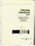
 Wiring Diagram &
Schematic
SAFETY WARNINGS
Safety Alert Symbols
The safety alert symbol (44) is used to
identify hazards that can result in personal
injury. A signal word (DANGER,
WARNING or CAUTION) is used with
the alert symbol to indicate the potential
severity of injury. In addition, a hazard
symbol may be used to represent the
type of hazard.
DANGER: Indicates a hazard
which, if not avoided will
result in death or serious
injury.
WARNING: Indicated a hazard
which, if not avoided could
result in death or serious
injury.
CAUTION: Indicates a hazard
which, if not avoided might
result in death or serious
injury.
CAUTION: When used without
the alert symbol, indicates a
situation that could result in
damage to equipment or
components.
HAZARD SYMBOLS AND MEANINGS
“ Ч
Explosion Fire Shock
ле
E сети
Entanglement Spark Plug
WD-SCH-01
ÁN DANGER
Physical contact with energized
electrical components will result
in dangerous and possibly fatal
electrical shock.
e Do not touch bare wires or
receptacies.
WD-SCH-04
ÁN DANGER
Generators produce powerful
voltages. Failure to isolate
generator from power utility
can result in death or injury to
electric utility workers due to
backfeed of electrical energy.
e When testing generators used for
backup power, notify utility company.
WD-SCH-05
ÁN CAUTION
These wiring diagrams and
schematics are intended for
use by trained and qualified
electrical service technicians
who are working in a properly
equipped service environment.
Familiarity with the proper
method of using tools,
measuring equipment and
service procedures is
essential to performing
successful troubleshooting and
repair of this equipment.
e Only qualified electrical technicians
should attempt to service this
equipment.
WD-SCH-02
CAUTION: The measuring
equipment used in troubleshooting
this equipment should be of industrial
quality and should have the sensitivity
to measure electronic values to the
third decimal. Its accuracy should
conform with acceptable industry
tolerances. Ensure that all specified
tools and/or equipment are available
before attempting to troubleshoot.
WD-SCH-03
Æà WARNING
Accidental starting of the unit
may cause entanglement or
electrocution.
@ Where applicable, disconnect the
negative (-) battery terminal.
® Disconnect the spark plug wire.
® Remove the control panel fuse
when available.
WD-SCH-07
Rev: 081805
7200 Watt Portable Generator
SCHEMATIC
11 O 11
22
022 VOLTAGE
REGULATOR
BLACK > 6 WHITE
o o
22
11 POWER POWER 44
y Р1-2 yo Y P1-1 V P1-4
TB-1 Y
TB-2
0 TB-3 22
Y
CB1 © ON
208 о/ o/
ETM
12V DC
HOURMETER
11 22
GF1
22
в 44B À 44A
CB2
15A
11A
q
TL
120/240V
WHITE 408
11A NY 444A
>
G
177
LOW OIL
SHUTDOWN
MODULE
13 hifi 55
BLK HI a
BLK 13 SC 16 a 0
SW
BLK BLK 13 1 13B_ Æ 0
o—0 e SC
—— LOW OIL PRESSURE 1A START RUN
° | — SWITCH 600V
ENG.
RUN GRN DCJ
SPARK SWITCH 0 136) 0
PLUG — 271
ENG.
IGNITION
SCHEMATIC
7200 Watt Portable Generator
WIRING DIAGRAM
CB3 CB?
1 2 1 2
e— a — —
x ETM
_ PELAR,
ТОЙ
|
22
11
(TN
CBI
e
1
Y) E
11
NN NN Y Y
44
LOCATED ON ENGINE
BLK
LOW OIL
PRESSURE — 22
SWITCH | гг
— 22 |
BLK LOW OIL HH
SHUTDOWN O TB
BLK MODULE o
ENGINE
RUN о /3| | 1
SWITCH 0
| 33 >
GRN 33 |
0 N [TN nm
ó Nr | _
NUT ON
ENGINE BLOCK
1A ”
600V —o
1A [= 4
115 1
13A
DCJ 55 —
0 9 9 VOLTAGE
REGULATOR
B
[+ | _ = = 22
POS NEG
Ц Ц
ВАТТЕВУ я e
12VDC
NOTE: POSITIVE BRUSH IS CLOSEST TO BEARING
WIRE DIAGRAM