1
SC & SI Remote Interface Description
en SC & SI Remote
Interface Description
SC & SI Remote Interface Description
en | 2
Table of Contents
1
Introduction ........................................................................................................................................3
Purpose ..........................................................................................................................................3
Scope..............................................................................................................................................3
Definitions, Acronyms and Abbreviations.......................................................................................3
References .....................................................................................................................................3
Overview.........................................................................................................................................3
2
System configuration and system installation ....................................................................................4
2.1
Introduction.....................................................................................................................................4
2.2
Remote System Configuration and System Installation .................................................................4
2.3
System Modes................................................................................................................................4
3
System Configuration Functions ........................................................................................................6
3.1
Introduction.....................................................................................................................................6
3.1.1
Remote function item explanation .......................................................................................6
3.2
SC_C_CHECK_LINK .....................................................................................................................6
3.3
SC_C_START_DCN ......................................................................................................................6
3.4
SC_C_STOP_DCN ........................................................................................................................7
3.5
SC_C_GET_CCU_VERSIONINFO................................................................................................7
3.6
SC_C_GET_CCU_CONFIG...........................................................................................................9
3.7
SC_C_START_DQS ....................................................................................................................10
3.8
SC_C_STOP_DQS ......................................................................................................................11
3.9
SC_C_MAINT_CCU_DB ..............................................................................................................11
3.10
SC_C_DOWNLOAD_CCU_DB ....................................................................................................12
3.11
SC_C_CLEAR_CCU_DB .............................................................................................................13
3.12
SC_C_CCU_APPLY_ONE...........................................................................................................14
4
System Configuration notifications...................................................................................................15
4.1
Introduction...................................................................................................................................15
4.1.1
Update Notification item explanation .................................................................................15
4.1.2
Unit/user event relations....................................................................................................15
4.2
SC_C_CCU_REBOOT .................................................................................................................17
4.3
SC_C_CONNECT_UNIT..............................................................................................................17
4.4
SC_C_DISCONNECT_UNIT........................................................................................................17
4.5
SC_C_CONNECT_SLAVE_CCU.................................................................................................17
4.6
SC_C_DISCONNECT_SLAVE_CCU...........................................................................................18
4.7
SC_C_CCU_MODE_CHANGE....................................................................................................18
5
System Installation Functions ..........................................................................................................19
5.1
Introduction...................................................................................................................................19
5.2
SI_C_START_INSTALL ...............................................................................................................19
5.3
SI_C_STOP_INSTALL .................................................................................................................19
5.4
SI_C_SELECT_UNIT ...................................................................................................................20
5.5
SI_C_SET_MASTER_VOL ..........................................................................................................21
6
System Installation notifications.......................................................................................................22
6.1
Introduction...................................................................................................................................22
6.1.1
Unit/user event relations....................................................................................................22
6.2
SI_C_REGISTER_UNIT...............................................................................................................22
Appendix A. Values of the defines..................................................................................................................23
Appendix B. Error Codes................................................................................................................................25
Appendix C. Examples ...................................................................................................................................27
C.1. Assigning seats using global installation ...........................................................................................27
C.2. Replacing defective units during operation........................................................................................28
Appendix D. Error Codes................................................................................................................................30
1.1
1.2
1.3
1.4
1.5
Bosch Security Systems B.V. | 2003 December | SC & SI Remote Interface Description
SC & SI Remote Interface Description
1
Introduction
1.1
Purpose
en | 3
The purpose of this document is to describe the remote interface for system configuration and system
installation. The document specifies the interface between the CCU and third party software.
1.2
Scope
This document describes the remote interface for system configuration and system installation. It is meant for
developers who want to use this remote interface to control/access system configuration and system
installation, present in the CCU, remotely.
For a complete description of the System Set-up can be referred to [SRS_INF].
1.3
Definitions, Acronyms and Abbreviations
CCU
DCN
SC
SI
DQS
OMF File
TCB
MTB
UnitId
remote controller
1.4
Central Control Unit. This can be either a Single-CCU system or a
Multi-CCU system.
Digital Congress Network
System Configuration
System Installation
Database Query Services
An executable file in a special format that can be programmed or
downloaded into the ReadOnlyMemory on the CCU
Trunc Communication Board
Multi Trunc Board
Unit identification, also called unit-number. A unique identification of
a unit within the CCU system.
Device (e.g. PC) connected to the CCU which remotely controls a
part of the applications present in the CCU.
References
[SRS_INF]
[USERDOC_DB]
[USERDOC_SI]
General Remote Interface Description
User Manual LBB 3580
User Manual LBB 3585
This document must be referenced as [SRS_SCSIINF].
1.5
Overview
Chapter 2 gives a brief explanation on System Configuration and System Installation. Also a short description
of the different CCU system modes is given in this chapter. For system configuration, the remote functions
and update notifications are described in chapters 3 and 4. For system installation, the remote functions and
update notifications are described in chapters 5 and 6.
Appendix Appendix A gives an overview of the constants used in combination with the remote functions and
update notifications described in this document.
Appendix Appendix B gives an overview of the possible error’s that could be returned upon execution of a
remote function.
Appendix Appendix C shows some examples on typical System Configuration or System Installation topics.
Bosch Security Systems B.V. | 2003 December | SC & SI Remote Interface Description
SC & SI Remote Interface Description
2
System configuration and system installation
2.1
Introduction
en | 4
The System Configuration and System Installation Remote Interface is part of the DCN software which allows
another controlling entity, not being the DCN Control PC, to use the System Configuration and System
Installation applications.
2.2
Remote System Configuration and System Installation
System Configuration (SC) is the application that monitors the hardware configuration of the congress system
and the link between hardware items and user information. Typical SC issues are, e.g. checking the
communication status, determining the system mode and replacing units.
System Installation (SI) is the application that allows for assigning seatnumbers to units to create a one to one
link between a unique user chosen identifier and a congress unit in the conference hall.
Maintaining the system configuration or performing a system installation with a remote interface is done by
means of calling a defined set of Remote Functions and acting upon a defined set of Update Notifications.
The general concept of remote functions and update notifications is described in [SRS_INF]. [SRS_INF] also
defines the protocol and hardware conditions concerning the remote interface. This document gives the set of
remote functions and the set of update notifications concerning SC and SI. The relation between remote
function and update notifications is given in the description of each separate remote function.
The system configuration and system installation process however, are also influenced by the actions of the
users performed upon the actual units. Actions such as pressing the microphone button or disconnecting a
unit from the system also results in update notifications being sent to the remote controller. The relation
between unit/user events and update notifications can be found in the user event matrices in sections 4.1.2
en 6.1.1.
2.3
System Modes
To understand the SC and SI functions, one should have some knowledge on the behaviour of the CCU
depending on the various so called system modes. This section gives a brief, although complete, description
of these modes.
The CCU system as a whole is always running in one of the system modes. Each application on the CCU has
its own behaviour in each system mode. The purpose of the system mode is to have a clear division of
functions and an easy way of separating them. It should be impossible for instance to start the installation
mode while the CCU is still booting, i.e. the CCU is in the Init-mode.
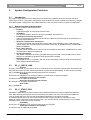
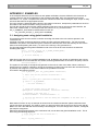
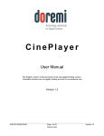
The following system modes are used:
init
One time mode after start-up of the CCU. The CCU can
start with default data (defined as ‘cold start’), or with data
the last time used (so called ‘warm start’).
config
In this system mode the DCN configuration can be
changed, for instance installing units, assigning
seatnumbers, assigning audio channels etc.
congress
This is the 'normal' system mode. In this mode most
applications will do their work, for instance starting a
voting round, turning on a microphone, interpreting etc.
maintenance In this system mode the DCN system can be maintained,
for instance testing microphones, testing audio channels,
factory testing and equalisation.
download
In this system mode new CCU software can be
downloaded.
down
One time system mode just before shutdown of the CCU.
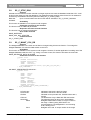
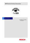
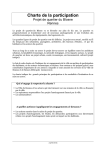
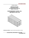
Figure 1 below gives an overview of possible system mode changes.
Bosch Security Systems B.V. | 2003 December | SC & SI Remote Interface Description
SC & SI Remote Interface Description
en | 5
Init
Config
Congress
Download
Maintenance
Down
Figure 1: CCU System modes
Some remote functions are supported in more than one system mode, or in an other mode than the congress
system mode.
Bosch Security Systems B.V. | 2003 December | SC & SI Remote Interface Description
SC & SI Remote Interface Description
3
System Configuration Functions
3.1
Introduction
en | 6
The system configuration functions described in this section are needed to query the set-up of the DCNsystem from the CCU. The system configuration functions allow the remote controller to monitor any changes
in the DCN system configuration. This chapter defines the set of remote functions for system configuration.
3.1.1
Remote function item explanation
Each description consists of the following items:
• Purpose
A global description of the purpose of the function.
• Availability
CCU System modes in which the function is available. See section 2.3.
• Parameter structure for the function
The input parameters needed to fulfil the function. When the function requires no parameters, no
structure is described here.
• Response structure from the function
The output information returned by the function called. This information is only valid when the
‘wError’ field of the received response information equals SC_E_NOERROR, SI_E_NOERROR or
DQSE_NOERROR.
• Error codes returned
The error values returned in the ‘wError’ field of the response information. All different error codes
are described in appendix Appendix B.
• Update notifications
The update notifications which are generated during the execution of the remote function. When
there are no notifications generated, then this part will be omitted.
• Related functions
The related function in conjunction with the function described. It refers to other remote functions
and to related update notifications.
3.2
SC_C_CHECK_LINK
Purpose
Function, which does no execution on the CCU. This function is to check the communication link between the
CCU and the remote controller. When executed, the function returns immediately. Therefor quickly returning
SC_E_NOERROR to the remote controller when there is a connection.
Availability
This function is available in CCU system mode's init, maintenance, config and congress.
Parameter structure for the function
The function has no additional parameters.
Response structure from the function
The function has no response parameters.
Error codes
SC_E_NOERROR
3.3
SC_C_START_DCN
Purpose
Indicates the CCU that the remote controller wants update notifications from the SC application inside the
CCU. After receiving this function the CCU increments the update ‘use’ count. As long as the update use
count is greater than zero, the CCU will send update notifications to the remote controller.
The returned update use count can be used to detect if the remote controller is connected too often.
When you omit the execution of this remote function, you can still execute remote functions, but no update
messages will be send to the remote controller.
Availability
This function is available in CCU system modes config and congress.
Parameter structure for the function
The function has no additional parameters.
Bosch Security Systems B.V. | 2003 December | SC & SI Remote Interface Description
SC & SI Remote Interface Description
en | 7
Response structure from the function
The function returns the following structure:
WORD
wNrOfInstances
where:
wNrOfInstances
The value of the update use count for the SC application at the
end of the function handling. It contains the number of times a
remote PC has been connected over the same communication
medium. E.g. the first time the function SC_C_START_DCN is
called, it contains the value 1.
Error codes returned
SC_E_NOERROR
Related functions
SC_C_STOP_DCN
3.4
SC_C_STOP_DCN
Purpose
Indicates the CCU that the remote controller no longer requires updates from the SC application inside the
CCU. After receiving this function the CCU decrements the update ‘use’ count. As long as the update use
count is greater than zero, the CCU remains sending the update notifications to the remote controller.
Note that:
Upon communication lost this function will be activated, if SC_C_START_DCN was
activated. The activation of this function is repeated till the update use count
becomes zero.
Availability
This function is available in CCU system modes config and congress.
Parameter structure for the function
The function has no additional parameters.
Response structure from the function
The function has the same response structure as the remote function SC_C_START_DCN (section 3.3).
Error codes returned
SC_E_NOERROR
Related functions
SC_C_START_DCN
3.5
SC_C_GET_CCU_VERSIONINFO
Purpose
This function is used to query the CCU version information. Usually this will be the first function called after
start-up of the remote controller to check the correct version of the CCU software.
Availability
This function is available in CCU all system modes.
Parameter structure for the function
The function has no additional parameters.
Response structure from the function
The function returns the following structure:
typedef struct
{
WORD tOperatingMode;
CHAR szSwVersion [SC_C_MAX_VERSION_LENGTH];
BYTE byMajorVersionOfDownloadedSw;
BYTE byMinorVersionOfDownloadedSw;
BYTE byMajorVersionOfResidentSw;
BYTE byMinorVersionOfResidentSw;
BYTE bySystemMode;
BYTE byReservedForSwInfo [SC_C_MAX_SOFTWARE_INFO];
SC_T_CCU_TYPE
tCCUType;
BYTE byMTBVersion;
BYTE byTCBVersion;
BYTE byReservedForHwInfo [SC_C_MAX_HARDWARE_INFO];
CHAR szSWRelNum[VERSION_C_LENGTH];
} SC_T_CCU_VERSION_INFO;
where:
tOperatingMode
The current operating mode of the CCU. It gives information
Bosch Security Systems B.V. | 2003 December | SC & SI Remote Interface Description
SC & SI Remote Interface Description
about the environment the CCU is functioning. The value is an
‘OR’ mask of the following settings:
• SC_C_STANDALONE
• SC_C_EXTENDED
• SC_C_SINGLETRUNC
• SC_C_MULTITRUNC
• SC_C_MASTER
• SC_C_SLAVE
szSwVersion
The current operating mode of the CCU in readable text. The
string is zero (‘\0’) terminated. If e.g. it is a Single CCU running
extended software, this string would read:
“EXTENDED SingleTrunc Version”.
byMajorVersionOfDownloadedSw, byMinorVersionOfDownloadedSw
The major and minor version numbers of the downloaded
software (OMF-file). If no downloaded software is present, then
both will be zero.
If e.g. the downloaded software is DCN 7.0,
byMajorVersionOfDownloadedSw will be ‘7’ and
byMinorVersionOfDownloadedSw will be ‘0’
byMajorVersionOfResidentSw, byMinorVersionOfResidentSw
The major and minor version numbers of the resident software
(Boot-software).
If e.g. the resident software is of version 2.1,
byMajorVersionOfResidentSw will be ‘2’ and
byMinorVersionOfResidentSw will be ‘1’.
bySystemMode
The Current System Mode of the CCU. Value according to
following type:
• DCNC_SM_DOWN
• DCNC_SM_INIT
• DCNC_SM_CONFIG
• DCNC_SM_CONGRESS
• DCNC_SM_MAINTENANCE
• DCNC_SM_DOWNLOAD
byReservedForSwInfo
Reserved space for extra software information.
tCCUType
Type of CCU connected to. Value according to following type:
• SC_C_LBB3500_00
• SC_C_LBB3500_10
• SC_C_LBB3500_30
• SC_C_LBB3511_00
byMTBVersion
Hardware version of the Multi-Trunk Board inside the CCU.
(zero if not present.)
byTCBVersion
Hardware version of the Trunk Communication Board inside the
CCU.
byReservedForHwInfo
Reserved space for extra hardware information.
szSWRelNum
Software version number as ASCII string. The string is zero
(‘\0’) terminated. Normally this is the string representation of
byMajorVersionOfDownloadedSw plus
byMinorVersionOfDownloadedSw, e.g. if the version of the
downloaded software is 7.00, this string will read “7.00”
Error codes returned
SC_E_NOERROR
Bosch Security Systems B.V. | 2003 December | SC & SI Remote Interface Description
en | 8
SC & SI Remote Interface Description
3.6
en | 9
SC_C_GET_CCU_CONFIG
Purpose
Retrieve information about all units connected to the congress network. This function returns for each unit
connected its unit-number and type.
Availability
This function is available in CCU system mode congress.
Parameter structure for the function
The function requires the following structure as parameter:
WORD
wClusterIndex;
where:
wClusterIndex
Determines which cluster is to be returned as response. Zero
(0) to retrieve the first cluster of SC_C_CLUSTER_MAX units.
One (1) for the second cluster of SC_C_CLUSTER_MAX units,
etc.
When the cluster is not completely filled, then that cluster is the
last cluster available.
All cluster indexes greater than this one will have an empty
tUnitData array. However, the other three elements of the
response structure will still contain correct data.
Response structure from the function
The function returns the following structure:
typedef struct
{
WORD wNumberOfSlaveCCUs;
WORD wNumberOfUnitsConnected;
WORD wNumberOfUnits;
SC_T_UNIT_DATA
tUnitData [SC_C_CLUSTER_MAX];
} SC_T_CCU_CONFIGURATION;
where the SC_T_UNIT_DATA is defined as:
typedef struct
{
WORD wUnitId;
BYTE byUnitType;
} SC_T_UNIT_DATA;
where:
wNumberOfSlaveCCUs
The number of Slave-CCU’s connected within a Multi-CCU
system, which ranges from 0 to 16. In case of a Single-CCU
system this number will be zero.
WNumberOfUnitsConnected
The actual number of units present in the system, even if the
total number is larger than the maximum size of the ‘tUnitData’
array. wNumberOfUnitsConnected ranges from 0 to
DBSC_MAX_ACT_UNIT.
When there are more units than the size of the ‘tUnitData’
structure, the structure is completely filled and the unit data for
the other units must be queried by using another clusterindex.
This number will be the same for all clusters requested.
wNumberOfUnits
The number of units present in the tUnitData array. Only this
amount of array elements is transmitted. This number will be
limited to the upper bound of the tUnitData array-size.
tUnitData []
Array holding the unit-information of each unit. Each array
element is defined as a SC_T_UNIT_DATA structure. The
elements of this structure are described below.
wUnitId
The unit identifier of a unit. Also called unit-number.
byUnitType
The type of the unit, which is on of the following:
• DCNC_UNIT_DELEGATE
Bosch Security Systems B.V. | 2003 December | SC & SI Remote Interface Description
SC & SI Remote Interface Description
en | 10
•
•
•
•
•
•
•
•
•
•
•
•
•
•
•
•
•
•
•
•
•
•
DCNC_UNIT_CHAIRMAN
DCNC_UNIT_DELEGATE_CARD
DCNC_UNIT_INTERPRETER
DCNC_UNIT_DUAL_MIC
DCNC_UNIT_PC
DCNC_UNIT_DATA_COMM
DCNC_UNIT_CCU_CONTROL
DCNC_UNIT_FLUSH_CHAIRMAN
DCNC_UNIT_FLUSH_DELEGATE
DCNC_UNIT_AMBIENT_MIC
DCNC_UNIT_DATA_COMM_RS232
DCNC_UNIT_2000_DELEGATE
DCNC_UNIT_2000_CHAIRMAN
DCNC_UNIT_2000_DELEGATE_CARD
DCNC_UNIT_AUDIO_IO
DCNC_UNIT_DAI_CHAIRMAN
DCNC_UNIT_DISC_DELEGATE
DCNC_UNIT_DISC_CHAIRMAN
DCNC_UNIT_ENTRANCE
DCNC_UNIT_EXIT
DCNC_UNIT_FLUSH_DEL_NODISP
DCNC_UNIT_FLUSH_CHR_NODISP
Note that future unit extensions of the DCN system can
lead to new unit-type, not presented in this list.
Error codes returned
SC_E_NOERROR
3.7
SC_C_START_DQS
Purpose
Indicate the CCU that the remote controller wants to communicate with the delegate database in the CCU.
When the execution of this remote function is omitted, all other remote database functions have no effect and
will return the error DQSE_APP_NOT_STARTED.
Availability
This function is available in CCU system mode congress.
Parameter structure for the function
The function requires the following structure as parameters.
typedef struct
{
BYTE byControlType;
} DQST_APP_CONTROL;
where:
byControlType
Identify that the remote controller likes to perform actions on the
database of the CCU. Valid values are:
• SC_C_DQS_CONTROL
The remote controller likes to have
control over the database of the CCU.
Note that the second start of the application (without a stop) always results in an error.
Response strcuture from the function
The function has no response parameters.
Error codes returned
DQSE_NOERROR
DQSE_INCONTROL_OTHER_CHANNEL
DQSE_INCONTROL_THIS_CHANNEL
DQSE_ILLEGAL_CONTROL_TYPE
Related functions
SC_C_STOP_DQS
Bosch Security Systems B.V. | 2003 December | SC & SI Remote Interface Description
SC & SI Remote Interface Description
3.8
en | 11
SC_C_STOP_DQS
Purpose
Indicate the CCU that the remote controller no longer requires to access the database inside the CCU. A call
to this function does not clear the database. The database present remains active till the CCU is restarted or
accessed by the database functions (after first calling SC_C_START_DQS).
Note that:
Upon communication loss this function will be activated, if SC_C_START_DQS was
activated.
Availability
This function is available in CCU system mode congress.
Parameter structure for the function
The function has no additional parameters.
Response strcuture from the function
The function has no response parameters.
Error codes returned
DQSE_NOERROR
DQSE_APP_NOT_STARTED
related functions
SC_C_START_DQS
3.9
SC_C_MAINT_CCU_DB
Purpose
The delegate database in the CCU can be filled or changed using this remote function. To manage the
delegate database, SC uses the DQS sublink on the CCU.
Availability
This function is available in CCU system mode congress. However, if another application is making use of the
delegate database inside the CCU, e,g, Voting or Access Control, this function will return the errorcode
DQSE_DELEGATE_DATA_BLOCKED
Parameter structure for the function
typedef struct
{
BOOLEAN bFirstCluster;
BOOLEAN bLastCluster;
SWORD
iPinSize;
SWORD
iFillLevel;
DQST_PERDELEGATE DelCluster[ DQSC_MAX_N_DL_DEL_REC];
} DQST_CCUMAINREC ;
with DQST_PERDELEGATE defined as :
typedef struct
{
DWORD
lDelId;
DWORD
lCard;
DWORD
lPin;
WORD wUnitNr;
SWORD
iDeskLang;
DWORD
lVWeight;
BOOLEAN bMicAut;
BOOLEAN bVotingAut;
BOOLEAN bInterAut;
CHAR szSLine [DBSC_NCHAR_SCREENLINE];
} DQST_PERDELEGATE;
where:
bFirstCluster
bLastCluster
iPinSize
iFillLevel
DelCluster;
lDelId
lCard
Indicates if this block is the first cluster.
Indicates if this block is the last cluster.
Indicated current pincode size. Possible values are 3,
4 and 5
The DelCluster array is filled with iFillLevel entries.
The following items per array entry are available :
Delegate identification number. A unique number in
the range 1..DBSC_MAX_DELEGATE. It is
recommended to use DelegateId’s in an increasing
order, starting from 1.
Delegate card code. A unique number in the range
Bosch Security Systems B.V. | 2003 December | SC & SI Remote Interface Description
SC & SI Remote Interface Description
en | 12
1..MAX_CARD_CODE. This is the numeric code
present on the identification card handed over to the
delegate and which is to be used in combination with
attendance registration and access control.
Delegate pincode. A numeric value in the range
lPin
111..555551. PIN codes are used for attendance
registration and access control, but do not have to be
unique.
The unit number that the delegate is assigned to by
wUnitNr
default. This unit number must equal UnitId retrieved
with SC_C_GET_CCU_CONFIG
Delegate display language. One of:
iDeskLang
• DCNC_VER_ENGLISH
• DCNC_VER_FRENCH
• DCNC_VER_GERMAN
• DCNC_VER_ITALIAN
• DCNC_VER_SPANISH
• DCNC_VER_SIXTH
Delegate vote weight. A value in the range
lVWeight
1..MAX_VOTE_WEIGTH to be used by the voting
application.
TRUE: this delegate has microphone authorisation.
bMicAut
FALSE: this delegate has no micro. authorisation
TRUE: this delegate has voting authorisation.
bVotingAut
FALSE: this delegate has no voting authorisation
TRUE: this delegate has intercom authorisation.
bInterAut
FALSE: this delegate has no intercom authorisation.
Delegate screenline. A string to represent a delegate
szSLine
e.g. on a Hall Display.
If more than DQSC_MAX_N_DL_DEL_REC records should be send to the CCU, more calls of this remote
function will be needed. In this case the ‘bFirstCluster’ and ‘bLastCluster’ indicate the start and termination of
the complete delegate database download.
Response structure from the function
The function has no response parameters.
Error codes returned
DQSE_NOERROR
DQSE_SET_PINSIZE_FAILED
(when pincode size update fails)
DQSE_DELEGATE_LIST_TOO_BIG
(when iFillLevel is greater than
DQSC_MAX_N_DL_DEL_REC)
DQSE_INSERT_DELEGATE_FAILED (when delegate insert failed)
DQSE_DELEGATE_DATA_BLOCKED
DQSE_APP_NOT_STARTED
Related functions
SC_C_START_DQS
SC_C_DOWNLOAD_CCU_DB
SC_C_CLEAR_CCU_DB
SC_C_CCU_APPLY_ONE
3.10
SC_C_DOWNLOAD_CCU_DB
Purpose
This function is equal to SC_C_MAINT_CCU_DB except that it does not contain a field for the delegates
screenline in the parameter structure.
1
Although the PIN code is identified as a variable of the type ‘long’, the real PIN code is a 6-based number. This means
that only digits 1 - 5 are allowed to be part of the PIN code. Besides, the PIN code also depends on the iPinSize variable.
If e.g. iPinSize is 3, the possible values for lPin range from 111 to 555. If iPinSize is 5 then lPin ranges from 11111 to
55555. So, lPin must always contain iPinSize digits in the range 1..5.
Bosch Security Systems B.V. | 2003 December | SC & SI Remote Interface Description
SC & SI Remote Interface Description
en | 13
Availability
This function is available in CCU system mode congress.
Parameter structure for the function
typedef struct
{
BOOLEAN bFirstCluster;
BOOLEAN bLastCluster;
SWORD
iPinSize;
SWORD
iFillLevel;
DQST_DEL_NO_SLINE
DelCluster [DQSC_MAX_N_DL_DEL_REC];
} DQST_CCUDOWNLOADREC ;
with DQST_DEL_NO_SLINE defined as :
typedef struct
{
DWORD
lDelId;
DWORD
lCard;
DWORD
lPin;
WORD wUnitNr;
SWORD
iDeskLang;
DWORD
lVWeight;
BOOLEAN bMicAut;
BOOLEAN bVotingAut;
BOOLEAN bInterAut;
} DQST_DEL_NO_SLINE;
All fields in the structures used within this function have the same meaning and range as the corresponding
fields of the structures used within SC_C_MAINT_CCU_DB.
Response structure from the function
The function has no response parameters.
Error codes returned
DQSE_NOERROR
DQSE_SET_PINSIZE_FAILED
(when pincode size update fails)
DQSE_DELEGATE_LIST_TOO_BIG
(when iFillLevel is greater than
DQSC_MAX_N_DL_DEL_REC)
DQSE_INSERT_DELEGATE_FAILED (when delegate insert failed)
DQSE_DELEGATE_DATA_BLOCKED
DQSE_APP_NOT_STARTED
Related functions
SC_C_START_DQS
SC_C_MAINT_CCU_DB
SC_C_CLEAR_CCU_DB
SC_C_CCU_APPLY_ONE
3.11
SC_C_CLEAR_CCU_DB
Purpose
This function clears the delegate database in the CCU.
Availability
This function is available in CCU system mode congress. As with SC_C_MAINT_CCU_DB this function
returns the error DQSE_DELEGATE_DATA_BLOCKED if another application is currently using the delegate
database in the CCU.
Parameter structure for the function
The function has no additional parameters.
Response structure from the function
The function has no response parameters.
Error codes returned
DQSE_NOERROR
DQSE_DELEGATE_DATA_BLOCKED
DQSE_APP_NOT_STARTED
Bosch Security Systems B.V. | 2003 December | SC & SI Remote Interface Description
SC & SI Remote Interface Description
en | 14
Related functions
SC_C_START_DQS
SC_C_MAINT_CCU_DB
SC_C_DOWNLOAD_CCU_DB
SC_C_CCU_APPLY_ONE
3.12
SC_C_CCU_APPLY_ONE
Purpose
With this function it is possible to add or update just one record in the delegate database in the CCU.
Note that using this function you can only add or update a record of an existing database on the CCU. You
cannot create a database using this function.
The delegateId as present in the structure is used to determine if the record will be added or updated:
• When the delegateId is not present in the database, the record will be added to the database.
• When the delegateId already exist in the database, the record of that delegate will be updated.
Only the following fields may be changed:
wUnitNr
Unit number where the delegate resides
iDesklang
Desk language of the delegate
lVWeight
Voting weight of the delegate
bMicAut
Microphone authorisation
bVotingAut
Voting authorisation
bInterAut
Intercom authorisation
szSline
The screenline of the delegate
All other fields of the structure must have the same value as the information stored in the database.
Availability
This function is available in CCU system mode congress.
Parameter structure for the function
DQST_PERDELEGATE
tDelegate (for description see section 3.9)
Response structure from the function
The function has no response parameters.
Error codes returned
DQSE_NOERROR
DQSE_UPD_DEL_UNIT_IN_USE
(if somebody else is using default seat)
DQSE_UPD_DEL_CARD_CHANGED
(if a card code change is detected)
DQSE_UPD_DEL_PIN_CHANGED
(if a pin code change is detected)
DQSE_UPDATE_DELEGATE_FAILED
(database function to update delegate record failed)
DQSE_INSERT_DELEGATE_FAILED
(database function to insert delegate record failed)
DQSE_NO_DATABASE
(No database available)
DQSE_APP_NOT_STARTED
Related functions
SC_C_START_DQS
SC_C_MAINT_CCU_DB
SC_C_DOWNLOAD_CCU_DB
SC_C_CLEAR_CCU_DB
Bosch Security Systems B.V. | 2003 December | SC & SI Remote Interface Description
SC & SI Remote Interface Description
4
System Configuration notifications
4.1
Introduction
en | 15
This chapter defines the set of update notifications concerning SC send by the CCU.
4.1.1
Update Notification item explanation
Each description consists of the following items:
• Purpose
A global description of the purpose of the notification.
• Notify structure with this update
The information passed with the update notification.
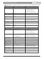
4.1.2
Unit/user event relations
In the previous chapter a description is given of each remote function with a summary of update notifications
being the result of executing that function. However, update notifications are also the results of user actions
done on the actual units or CCU’s. This section gives unit/user event matrices for the SC application in which
the possible user events are linked with the corresponding update notification(s) depending on the system
set-up. For some events also the required remote functions to continue SC monitoring and maintaining are
given.
The update notifications themselves are described in the remaining sections of this chapter. The
recommended functions from the SI group are described in chapter 5.
UNIT-EVENT MATRIX
Single CCU System (Remote Controller connected as specified in [SRS_INF])
Event
Update Notification
Continue with remote function
Switch On CCU
SC_C_CCU_REBOOT
Connect a unit
SC_C_CONNECT_UNIT
Disconnect a unit
SC_C_DISCONNECT_UNIT
SC_C_START_DCN
Recommended before continuing:
SC_C_GET_CCU_VERSIONINFO
SC_C_GET_CCU_CONFIG
SI_C_START_INSTALL and run
installation as described in
example-1 in Appendix Appendix C
Recommended before continuing:
SI_C_START_INSTALL and run
installation as described in
example-2 in Appendix Appendix C
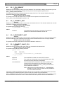
Multi CCU System (Remote Controller connected to the Master as specified in [SRS_INF])
Event
Update Notification
Continue with remote function
Switch On a Slave
CCU, while Master CCU
is still off
Switch On Master CCU
Switch On a Slave CCU
Switch Off a Slave
CCU
Connect a Unit
Disconnect a Unit
<None>
SC_C_CCU_REBOOT
SC_C_CONNECT_SLAVE_CCU
and a few seconds later for
every unit connected to that
Slave CCU separately
SC_C_CONNECT_UNIT
SC_C_DISCONNECT_SLAVE_CCU
SC_C_CONNECT_UNIT
SC_C_START_DCN
Recommended before continuing:
SC_C_GET_CCU_VERSIONINFO
SC_C_GET_CCU_CONFIG
SI_C_START_INSTALL and run
installation as described in
example-1 in Appendix Appendix C
Recommended before continuing on
the unit connect updates:
SI_C_START_INSTALL and run
installation as described in
example-2 in Appendix Appendix C
Recommended before continuing:
SI_C_START_INSTALL and run
installation as described in
example-2 in Appendix Appendix C
SC_C_DISCONNECT_UNIT
Bosch Security Systems B.V. | 2003 December | SC & SI Remote Interface Description
SC & SI Remote Interface Description
en | 16
Single-Multi System, i.e. a Multi CCU system but one or more of the Slave CCU’s configured to run in Single
Mode
Event
Update Notification
Continue with remote function
Remote Controller connected to CCU-A, a CCU configured to run in Single CCU mode
Switch On CCU-A
SC_C_CCU_REBOOT
Switch On the Master
CCU
Switch On another CCU
(Slave or SingleMode)
Disconnect another
CCU (Slave or SingleMode)
Connect a unit to
CCU-A.
<None>
Disconnect a unit
from CCU-A.
Connect a unit to
another CCU (Slave or
Single-Mode).
Disconnect a unit
from another CCU
(Slave or SingleMode).
SC_C_DISCONNECT_UNIT
SC_C_START_DCN
Recommended before continuing:
SC_C_GET_CCU_VERSIONINFO
SC_C_GET_CCU_CONFIG
SI_C_START_INSTALL and run
installation as described in
example-1 in Appendix Appendix C
<None>
<None>
SC_C_CONNECT_UNIT
Recommended before continuing:
SI_C_START_INSTALL and run
installation as described in
example-2 in Appendix Appendix C
<None>
<None>
Remote Controller connected to the Master CCU
Switch On CCU-A
Switch On the Master
CCU.
<None>
SC_C_CCU_REBOOT
Switch On a Slave CCU
SC_C_CONNECT_SLAVE_CCU
and a few seconds later for
every unit connected to that
Slave CCU separately
SC_C_CONNECT_UNIT
<None>
Switch On another
Single-Mode CCU
Switch Off a Slave
CCU
Switch Off another
Single-Mode CCU
Connect a unit to
CCU-A.
Disconnect a unit
from CCU-A.
Connect a unit to a
Slave CCU.
Disconnect a unit
from a Slave CCU.
Connect a unit to
another Single-Mode
CCU.
Disconnect a unit
from another SingleMode CCU.
SC_C_START_DCN
Recommended before continuing:
SC_C_GET_CCU_VERSIONINFO
SC_C_GET_CCU_CONFIG
SI_C_START_INSTALL and run
installation as described in
example-1 in Appendix Appendix C
Recommended before continuing on
the unit connect updates:
SI_C_START_INSTALL and run
installation as described in
example-2 in Appendix Appendix C
SC_C_DISCONNECT_SLAVE_CCU
<None>
<None>
<None>
SC_C_CONNECT_UNIT
Recommended before continuing:
SI_C_START_INSTALL and run
installation as described in
example-2 in Appendix Appendix C
SC_C_DISCONNECT_UNIT
<None>
<None>
Bosch Security Systems B.V. | 2003 December | SC & SI Remote Interface Description
SC & SI Remote Interface Description
4.2
en | 17
SC_C_CCU_REBOOT
Purpose
Notifies the remote controller that the CCU has restarted. This notification is always send at start-up of the
CCU and is the only notification message send by the CCU till the update request function
SC_C_START_DCN is executed.
This notification should be monitored to detect a restart of the CCU. The remote controller should take
appropriate actions to restore the settings.
Notify structure with this update
The update comes with the same structure as used for the response of the remote function
SC_C_GET_CCU_VERSIONINFO (section 3.5).
4.3
SC_C_CONNECT_UNIT
Purpose
Notifies the remote controller that a new unit has connected to the CCU. The remote controller can use this
notification to add this unit to its functionality.
Notify structure with this update
The update uses the following structure:
SC_T_UNIT_DATA
tUnitData;
where:
tUnitData
4.4
Information about the unit that is connected. The elements
present in the structure are defined in section 3.6.
SC_C_DISCONNECT_UNIT
Purpose
Notifies the remote controller that a unit has lost his connection with the CCU (i.e. the unit is disconnected
from the ACN-trunk). This notification informs the remote controller that the unit is no longer available.
Notify structure with this update
The update comes along with the same structure as defined in section 4.3.
4.5
SC_C_CONNECT_SLAVE_CCU
Purpose
Notifies the remote controller that a slave-CCU has connected to the master-CCU.
Notify structure with this update
The update comes with the following structure:
typedef struct
{
BYTE
bySlaveId;
WORD
wFillLevel;
SC_T_UNIT_DATA
tConnectedUnits[SC_C_CLUSTER_MAX];
} SC_T_CCU_CONNECT;
where:
bySlaveId
The identification number of the slave-CCU involved.
wFillLevel
The number of units present in the tConnectedUnits array. Only
this amount of array elements is transmitted.
tConnectedUnits
A list of units that are connected to the slave in question. This
means that all units reported in the list are also connected.
Each list element is defined as a SC_T_UNIT_DATA structure
which is defined in section 3.6.
Note: Although the list is defined with SC_C_CLUSTER_MAX
elements, only the maximum number of units possible for
one slave will be transmitted.
Currently the wFillLevel parameter will always be zero. Due to the nature of the units and the control flow
used with the CCU (slave and master), each unit will connect itself using the notification
SC_C_CONNECT_UNIT. Therefor no units are reported in this list. Future extension in the software could
build a list of units connected to a slave. That list should then be reported in the tConnectedUnits list.
Bosch Security Systems B.V. | 2003 December | SC & SI Remote Interface Description
SC & SI Remote Interface Description
4.6
en | 18
SC_C_DISCONNECT_SLAVE_CCU
Purpose
Notifies the remote controller that the master-CCU has lost connection to one of his slave-CCU’s. Along with
this notification a list of all units connected to that slave is send. This notification tells the remote controller
that the listed units are no longer available.
Notify structure with this update
The update comes with the following structure:
typedef struct
{
BYTE
bySlaveId;
WORD
wFillLevel;
SC_T_UNIT_DATA
tDisconnectedUnits[SC_C_CLUSTER_MAX];
} SC_T_CCU_DISCONNECT;
where:
bySlaveId
The identification number of the slave-CCU involved.
wFillLevel
The number of units present in the tDisconnectedUnits array.
Only this amount of array elements is transmitted.
tDisconnectedUnits
A list of units that are connected to the slave in question at the
moment of disconnecting the slave. This means that all units
reported in the list are also disconnected. Each list element is
defined as a SC_T_UNIT_DATA structure which is defined in
section 3.6.
Note: Although the list is defined with SC_C_CLUSTER_MAX
elements, only the maximum number of units possible for
one slave will be transmitted.
This notification differs from SC_C_CONNECT_SLAVE_CCU such that wFillLevel and the
tDisconnectedUnits array does inform the remote controller about units being disconnected together with this
Slave-CCU. This implies that the units listed in the ‘tDisconnectedUnits’ do not notify themselves as
disconnected with SC_C_DISCONNECT_UNIT.
4.7
SC_C_CCU_MODE_CHANGE
Purpose
Notifies the remote controller that the CCU changed its operation mode. For more information about the
different modes see 3.5.
Notify structure with this update
typedef struct
{
WORD
wCurrentMode;
WORD
wNewMode;
} SC_T_CCU_MODE_CHANGE;
where:
wCurrentMode
wNewMode
The current CCU system mode, so before the mode
change. Possible system mode values are defined in the
bySystemMode field of the structure used within the
function SC_C_GET_CCU_VERSIONINFO (see section
3.5 ).
The new CCU system mode, so after the mode change.
Bosch Security Systems B.V. | 2003 December | SC & SI Remote Interface Description
SC & SI Remote Interface Description
5
System Installation Functions
5.1
Introduction
en | 19
The system installation functions provide functionality to connect unit identification with the seat numbers
used within the congress-hall. This process is also called seat-assignment. This chapter defines the set of
remote functions needed for system installation. Each description is according to the definition given in
section 3.1.1.
5.2
SI_C_START_INSTALL
Purpose
Start the installation mode. The remote controller can choose among 2 modes of installation, which are:
Mode
Description
SI_C_GLOBAL_INSTALL_MODE
Global installation mode. When activating this mode, the CCU stops all
applications running and only runs the installation application. When the
function is successfully executed, the CCU has changed the system mode
from congress to config.
Entering the system mode config enables the update notification
SI_C_REGISTER_UNIT which informs the remote controller about
someone pressing a soft-key on a unit. The remote controller must use this
notification message to link the unit with a seat.
By pressing a soft-key on all units in order of the seat-numbers the remote
controller can build a list of units with the seat-numbers as index. An
example using this mode is presented in appendix Appendix C.
SI_C_OPERATIONAL_INSTALL_MODE
Operational installation mode. During this mode all applications keep on
running. The CCU remains in the congress mode.
No special update notification for registration will be enabled. The remote
controller must select a proposed unit and the seat-number must be
searched to link them together.
To finish the installation the remote controller must execute the function SI_C_STOP_INSTALL.
Availability
This function is available in CCU system mode congress.
Parameter structure for the function
The function requires the following information as parameter:
WORD
wInstallMode;
where:
wInstallMode
The installation mode to be used. This parameter can have one
of the following values:
• SI_C_GLOBAL_INSTALL_MODE
• SI_C_OPERATIONAL_INSTALL_MODE
Response structure from the function
The function has no response parameters.
Error codes returned
SI_E_NOERROR
SI_E_FAILED
(SI mode already in use)
Update Notifications
SC_C_CCU_MODE_CHANGE
Related functions
SI_C_STOP_INSTALL
SI_C_SELECT_UNIT
5.3
SI_C_STOP_INSTALL
Purpose
This function stops the installation started with the function SI_C_START_INSTALL. The CCU will return to
normal congress mode if that is not the current system mode. The selected units will be deselected.
Bosch Security Systems B.V. | 2003 December | SC & SI Remote Interface Description
SC & SI Remote Interface Description
en | 20
Note that:
Upon communication loss this function will be activated, if SI_C_START_INSTALL
was activated.
Availability
This function is available in CCU system mode config.
Parameter structure for the function
The function has no additional parameters.
Response structure from the function
The function has no response parameters.
Error codes returned
SI_E_NOERROR
SI_E_FAILED
(another controller has the SI mode in use)
Update Notifications
SC_C_CCU_MODE_CHANGE
Related functions
SI_C_START_INSTALL
SI_C_SELECT_UNIT
5.4
SI_C_SELECT_UNIT
Purpose
Select a unit for linking to a seat by means of flashing all LED’s on the unit. Only one unit can be selected at
the same time. When the second unit is selected the first unit is deselected automatically before the selection
of the second.
This function will only select a unit if the unit selected represents an installable unit. An installable unit is an
unit which can be assigned with a seat number.
Installable unit types are
DCNC_UNIT_DELEGATE
DCNC_UNIT_CHAIRMAN
DCNC_UNIT_DELEGATE_CARD
DCNC_UNIT_DUAL_MIC
DCNC_UNIT_FLUSH_CHAIRMAN
DCNC_UNIT_FLUSH_DELEGATE
DCNC_UNIT_2000_DELEGATE
DCNC_UNIT_2000_CHAIRMAN
DCNC_UNIT_2000_DELEGATE_CARD
DCNC_UNIT_DAI_CHAIRMAN
DCNC_UNIT_DISC_DELEGATE
DCNC_UNIT_DISC_CHAIRMAN
DCNC_UNIT_FLUSH_DEL_NODISP
DCNC_UNIT_FLUSH_CHR_NODISP
When called during the installation mode SI_C_GLOBAL_INSTALL_MODE the microphone of the unit will be
turned on as long as the unit is selected.
Availability
This function is available in CCU system modes config and congress.
Parameter structure for the function
The function requires the following structure as parameter:
typedef struct
{
WORD
wUnitId;
BOOLEAN
bSelectOn;
} SI_T_SELECT_UNIT;
where:
wUnitId
The unit identifier of the unit selected.
bSelectOn
TRUE: All LED’s of the unit will be flashing.
FALSE: All LED’s of the unit will be off
Response structure from the function
The function has no response parameters.
Bosch Security Systems B.V. | 2003 December | SC & SI Remote Interface Description
SC & SI Remote Interface Description
en | 21
Error codes returned
SI_E_NOERROR
SI_E_FAILED
SI_E_INVALID_UNITTYPE
Related functions
SI_C_START_INSTALL
SI_C_STOP_INSTALL
5.5
SI_C_SET_MASTER_VOL
Purpose
To set the master audio volume. The audio loudness of the delegates loudspeakers, line-out and rec-out can
be changed.
Availability
This function is available in CCU system modes config and congress.
Parameter structure for the function
WORD
wMasterVolume;
where:
wMasterVolume
The new overall volume setting for the system. A number in
the range 0..15. In this range, a zero value means mute all
delegate loudspeakers. The values 1 up untill 15 correspond
with an audio amplification of -14dB up untill 0dB in steps of
1 dB.
Response structure from the function
The function has no response parameters.
Error codes returned
SI_E_NOERROR
SI_E_FAILED
Bosch Security Systems B.V. | 2003 December | SC & SI Remote Interface Description
SC & SI Remote Interface Description
6
System Installation notifications
6.1
Introduction
en | 22
This chapter defines the set of update notifications concerning SI send by the CCU. Each description is
according to the definition given in section 4.1.1.
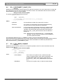
6.1.1
Unit/user event relations
As for the SC application, update notifications for SI are also the results of user actions done on the actual
units. This section gives a unit/user event matrix for the SI application in which the possible user events are
linked with the corresponding update notification(s). For some events also the required remote functions to
continue the System Installation process are given.
The update notifications themselves are described in the remaining sections of this chapter.
UNIT-EVENT MATRIX
Event
Update Notification
Continue with remote function
Installation not yet started
Press a Soft-key on
<None>
a unit
Started Installation with SI_C_START_INSTALL (SI_C_GLOBAL_INSTALL_MODE)
Press a Soft-key on
SI_C_REGISTER_UNIT
SI_C_SELECT_UNIT
a unit
See example-1 in Appendix Appendix
C
Started Installation with SI_C_START_INSTALL (SI_C_OPERATIONAL_INSTALL_MODE)
Press a Soft-key on
<None>
a unit
6.2
SI_C_REGISTER_UNIT
Purpose
Notifies the remote controller that during global installation (which implies that the CCU is in config mode, see
SI_C_START_INSTALL section 5.2) a soft key is pressed on a installable unit. A installable unit is a unit
which can be assigned with a seat number.
An overview of installable unit types is given in section 5.4.
The remote controller should use this update to assign a seat number to the unit identifier given with this
update notification.
Notify structure with this update
The update comes with the following structure:
typedef struct
{
WORD wUnitId;
BYTE byUnitType;
} SI_T_UNIT_STRUCT;
where:
wUnitId
The unit identifier of a unit. Also called unit-number.
byUnitType
The type of the unit. The different unit types possible are given
in section 3.6.
Bosch Security Systems B.V. | 2003 December | SC & SI Remote Interface Description
SC & SI Remote Interface Description
en | 23
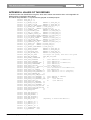
APPENDIX A. VALUES OF THE DEFINES
In this document a lot of definitions are given, which have values connected to them. In this appendix all
defines will be connected to their values.
The values are presented in ‘C’-syntax and are grouped on related purpose.
#define DCNC_APP_SI 17
#define DCNC_APP_SC 16
#define
#define
#define
#define
#define
#define
#define
#define
#define
#define
#define
#define
#define
#define
#define
#define
#define
SC_C_MAINT_CCU_DB
MKWORD (1,DCNC_APP_SC)
SC_C_CLEAR_CCU_DB
MKWORD (2,DCNC_APP_SC)
SC_C_GET_CCU_VERSIONINFO MKWORD (6,DCNC_APP_SC)
SC_C_START_DCN
MKWORD (7,DCNC_APP_SC)
SC_C_STOP_DCN
MKWORD (8,DCNC_APP_SC)
SC_C_CONNECT_UNIT
MKWORD (9,DCNC_APP_SC)
SC_C_DISCONNECT_UNIT
MKWORD (10,DCNC_APP_SC)
SC_C_GET_CCU_CONFIG
MKWORD (12,DCNC_APP_SC)
SC_C_CONNECT_SLAVE_CCU
MKWORD (13,DCNC_APP_SC)
SC_C_DISCONNECT_SLAVE_CCUMKWORD (14,DCNC_APP_SC)
SC_C_CCU_REBOOT MKWORD (15,DCNC_APP_SC)
SC_C_CCU_MODE_CHANGE
MKWORD (16,DCNC_APP_SC)
SC_C_CCU_APPLY_ONE
MKWORD (17,DCNC_APP_SC)
SC_C_CHECK_LINK MKWORD (18,DCNC_APP_SC)
SC_C_DOWNLOAD_CCU_DB
MKWORD (20,DCNC_APP_SC)
SC_C_START_DQS
MKWORD (21,DCNC_APP_SC)
SC_C_STOP_DQS
MKWORD (22,DCNC_APP_SC)
#define
#define
#define
#define
#define
SI_C_SELECT_UNIT MKWORD (1,DCNC_APP_SI)
SI_C_START_INSTALL
MKWORD (4,DCNC_APP_SI)
SI_C_STOP_INSTALL
MKWORD (5,DCNC_APP_SI)
SI_C_REGISTER_UNIT
MKWORD (9,DCNC_APP_SI)
SI_C_SET_MASTER_VOL
MKWORD (10,DCNC_APP_SI)
#define DBSC_MAX_ACT_UNIT
#define DBSC_MAX_DELEGATE
#define DBSC_NCHAR_SCREENLINE
512 single CCU system, 4000 multi CCU system
DBSC_MAX_ACT_UNIT
33
#define
#define
#define
#define
#define
#define
#define
#define
#define
#define
#define
#define
#define
#define
#define
#define
#define
#define
#define
#define
#define
#define
#define
DCNC_UNIT_DELEGATE
1
(unit LBB3550/00 or LBB3551/00)
DCNC_UNIT_CHAIRMAN
2
(unit LBB3554/00)
DCNC_UNIT_DELEGATE_CARD 3
(unit LBB3550/10 or LBB3551/10)
DCNC_UNIT_INTERPRETER
4
(unit LBB3520/00)
DCNC_UNIT_DUAL_MIC
5
(unit LBB3535/00)
DCNC_UNIT_PC 6
(Network card for PC LBB3510/00)
DCNC_UNIT_DATA_COMM
7
(Data Distribution board LBB3512/00)
DCNC_UNIT_CCU_CONTROL
8
(CCU LBB3500/xx)
DCNC_UNIT_FLUSH_CHAIRMAN 10
(unit LBB3540/00 set to ‘chairman’)
DCNC_UNIT_FLUSH_DELEGATE 11
(unit LBB3540/00 set to ‘delegate’)
DCNC_UNIT_AMBIENT_MIC
13
DCNC_UNIT_DATA_COMM_RS23215
DCNC_UNIT_2000_DELEGATE 17
(unit LBB3544 or LBB3545)
DCNC_UNIT_2000_CHAIRMAN 18
(unit LBB3546)
DCNC_UNIT_2000_DELEGATE_CARD 19
(unit LBB3547)
DCNC_UNIT_AUDIO_IO
20
(unit LBB3513)
DCNC_UNIT_DAI_CHAIRMAN
21
DCNC_UNIT_DISC_DELEGATE 22
DCNC_UNIT_DISC_CHAIRMAN 23
DCNC_UNIT_FLUSH_DEL_NODISP
26
DCNC_UNIT_FLUSH_CHR_NODISP
27
DCNC_UNIT_ENTRANCE
30
DCNC_UNIT_EXIT
31
#define
#define
#define
#define
#define
#define
DCNC_VER_ENGLISH
DCNC_VER_FRENCH
DCNC_VER_GERMAN
DCNC_VER_ITALIAN
DCNC_VER_SPANISH
DCNC_VER_SIXTH
0
1
2
3
4
5
#define
#define
#define
#define
SC_C_LBB3500_00
SC_C_LBB3500_10
SC_C_LBB3500_30
SC_C_LBB3511_00
0
1
3
4
#define SC_C_STANDALONE
#define SC_C_EXTENDED
(depending on downloaded OMF-file)
0x01
0x02
Bosch Security Systems B.V. | 2003 December | SC & SI Remote Interface Description
SC & SI Remote Interface Description
#define
#define
#define
#define
en | 24
SC_C_SINGLETRUNC 0x04
SC_C_MULTITRUNC 0x08
SC_C_MASTER 0x10
SC_C_SLAVE
0x20
#define SI_C_GLOBAL_INSTALL_MODE 1
#define SI_C_OPERATIONAL_INSTALL_MODE 2
#define SC_C_DQS_CONTROL 1
#define
#define
#define
#define
SC_C_MAX_HARDWARE_INFO
SC_C_CLUSTER_MAX 1500
SC_C_MAX_SOFTWARE_INFO
SC_C_MAX_VERSION_LENGTH
#define
#define
#define
#define
DQSC_MAX_N_DL_DEL_REC
50
VERSION_C_LENGTH 50
MAX_CARD_CODE
999999999
MAX_VOTE_WEIGTH 99999999
#define
#define
#define
#define
#define
#define
DCNC_SM_DOWN 0
DCNC_SM_INIT 1
DCNC_SM_CONFIG
2
DCNC_SM_CONGRESS 3
DCNC_SM_MAINTENANCE
DCNC_SM_DOWNLOAD 5
#define TRUE 1
#define FALSE
50
29
50
4
0
Bosch Security Systems B.V. | 2003 December | SC & SI Remote Interface Description
SC & SI Remote Interface Description
en | 25
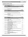
APPENDIX B. ERROR CODES
Responses returned upon a remote function request contain an error field (‘wError’). In this appendix an
overview is given of the possible errors and their values.
System Configuration Error code
Value
Explanation
0
SC_E_NOERROR
The execution of the remote function was successful.
1
SC_E_FAILED
The execution of the remote function failed. This error code is
currently not used.
System Installation Error code
Explanation
SI_E_NOERROR
The execution of the remote function was successful.
SI_E_FAILED
The execution of the remote function failed. Only one remote
controller (currently using the installation mode) may use this
remote function.
SI_E_INVALID_UNITTYPE
The selected unit represents no seat. For example the entry exit
unit and interpreter desks.
Value
Database Query Services Error code
Explanation
DQSE_NOERROR
The execution of the remote function was successful.
DQSE_SET_PINSIZE_FAILED
Setting a new size for the PIN Code into the Delegate Database
failed.
DQSE_DELEGATE_LIST_TOO_BIG
The iFillLevel parameter in SC_C_MAINT_CCU_DB has a value
larger then DQSC_MAX_N_DL_DEL_REC.
DQSE_INSERT_DELEGATE_FAILED
Inserting the current DQST_PERDELEGATE structure into the
Delegate Database failed.
DQSE_UPDATE_DELEGATE_FAILED
Updating the delegate database with the current
DQST_PERDELEGATE structure failed.
DQSE_UPD_DEL_PIN_CHANGED
Update failed because the PIN code changed.
DQSE_UPD_DEL_CARD_CHANGED
Update failed because the cardcode is changed.
DQSE_UPD_DEL_UNIT_IN_USE
Update of database failed because someone else is already using
the proposed default seat.
DQSE_PENDING_REQUEST
Setting/updating the Delegate Database failed because a delegate
with a pending Request to Speak was tried to delete from the
database.
DQSE_DELEGATE_DATA_BLOCKED
Updating the delegate database with the current
DQST_PERDELEGATE structure failed.
DQSE_NO_DATABASE
Value
Bosch Security Systems B.V. | 2003 December | SC & SI Remote Interface Description
0
1
4323
0
10401
10402
10403
10404
10405
10406
10407
10408
10409
10410
SC & SI Remote Interface Description
Database Query Services Error code
Value
Explanation
The use of function SC_C_CCU_APPLY_ONE is not possible,
because currently there is no database present in the CCU.
10411
DQSE_APP_NOT_STARTED
The remote controller has not called the SC_C_START_DQS yet.
Therefore any remote function call to access the database fails with
this error.
10412
DQSE_INCONTROL_THIS_CHANNEL
The database is already under control by this remote controller (on
the same channel). Probably you have called the
SC_C_START_DQS function twice.
10413
DQSE_INCONTROL_OTHER_CHANNEL
The SC_C_START_DQS function could not finish successfully
because the database is already controlled by another remote
controller using another channel.
10414
DQSE_ILLEGAL_CONTROL_TYPE
The control-type passed to the function SC_C_START_DQS is not
within range of valid values (see appendix Appendix A for the
correct control-type values).
Bosch Security Systems B.V. | 2003 December | SC & SI Remote Interface Description
en | 26
SC & SI Remote Interface Description
en | 27
APPENDIX C. EXAMPLES
In the examples below the remote functions and update notifications, that are defined in this document as
constant values for the wFnId parameter of the message (see [SRS_INF]), are presented as functions
described in a ‘C’ syntax. The parameter structures of these functions are according the input, output or notify
structures described in the appropriate section.
For every function is assumed that the function will create his structure, transport the parameters to the CCU
and waits for the result information coming from the CCU.
For both the remote functions as the update notifications the same names are used as their identifier, but
without the constant mark “C” and using mixed case names. So, e.g. remote function
SC_C_CONNECT_UNIT shall be referenced as function as:
SC_Connect_Unit (SC_T_UNIT_DATA tUnitData);
C.1. Assigning seats using global installation
This example shows how the remote controller can assign his seats to the unit-numbers present in the
conference hall.
Assumed is that the conference hall has a number of seats numbered starting with 1. For this proposed
installation one person must walk through the conference hall and press one of the soft-keys on the units in
order of the seats (starting with seat 1). On each unit a soft-key is only pressed once.
For this seat assignment the global installation mode of the CCU will be used. therefore we start with
activating that mode.
error = SI_Start_Install (SI_C_GLOBAL_INSTALL_MODE);
if (error != SI_E_NOERROR)
{
/* do error handling */
}
After this function the CCU is in global installation mode, all displays are off and no applications are running.
We now initialise the current seat and unit-number, assuming seatnumbers are chosen to be purely numeric:
wCurrentSeatNumber = 1;
The system is now ready to accept the key-presses on the units in order of the seats. When a soft-key is
pressed the CCU sends a notification. During the processing of that function we select the unit where the key
is pressed, and assign the current seat number to the provided unit number.
This result in the following function:
void SI_Register_Unit (SI_T_UNIT_STRUCT *tUnitStruct)
{
/* First turn off the previous selected unit */
/* ........ */
error = SI_Select_Unit (tUnitStruct->wUnitId, TRUE);
if (error != SI_E_NOERROR)
{
/* do error handling */
}
/* assign the current seat to the unit */
MyAssignSeat (wCurrentSeatNumber, tUnitStruct->wUnitId);
/* Increment to the next seat */
wCurrentSeatNumber = wCurrentSeatNumber + 1;
/* and save the unitId to turn off during the assignment of the next seat */
/* ........ */
}
Note that this function is only an example to shown how the interaction between update notifications and
remote functions can appear. For instance, when you press a soft-key the second time, this function will fail.
Better is to look if the selected unit has already a seat assigned. If not, the assign and increment, if assigned,
just keep the assignment.
When done with all seats present in the conference hall, we can leave the global installation mode. This is
done using the following sequence:
/* first turn off the last selected unit */
/* ........ */
error = SI_Stop_Install ();
Bosch Security Systems B.V. | 2003 December | SC & SI Remote Interface Description
SC & SI Remote Interface Description
en | 28
if (error != SI_E_NOERROR)
{
/* do error handling */
}
This ends the global seat assignment. The remote controller has now a complete list of all seats and their
corresponding unit-numbers.
C.2. Replacing defective units during operation
This example shows how the remote controller can assign a seat to a unit in the conference hall which is
replaced by a new unit (due to failure of the old unit).
Assumed is that previously all units have been assigned a seat-number on the remote controller. After
detection that a unit fails, the following actions are performed by the technical staff of the conference hall:
1. The defective unit is removed from the system. Note that disconnecting the unit also may
disconnect other (chained) units.
2. A new unit is inserted into the unit-chain and connected to the system.
3. The new unit is de-initialised, and initialised again to be sure that the added unit has no
address conflict with other units.
During these actions the following notifications are reported to the remote controller (assumed is that the
application SC is registered by the CCU:
• Microphone off notifications if any of the disconnected units has their microphone on or
had a pending request (present in the Request To Speak list).
• SC_C_DISCONNECT_UNIT for all units in the chain disconnected. The remote controller
remembers these units to disable the functionality.
• SC_C_CONNECT_UNIT for all units connected. Most of the unit-numbers are known in
the disconnect-list and can be restored (e.g. the functionality will be enabled). The new
unit(s) connected to the system is not known.
For these units the remote controller must start the operational installation mode. The operational installation
mode is activated using the following remote function request:
error = SI_Start_Install (SI_C_OPERATIONAL_INSTALL_MODE);
if (error != SI_E_NOERROR)
{
/* do error handling */
}
After this the CCU has enabled the operational installation mode. The remote controller can start the
sequence to assign the new unit-numbers to seats not yet assigned.
while (there are new units and unassigned seats)
{
WORD wUnitId;
wUnitId = First_new_unit_available;
/* select the unit */
error = SI_Select_Unit (wUnitId, TRUE);
if (error != SI_E_NOERROR)
{
/* do error handling */
}
/* Let the operater determine which seat should be assigned to the selected
unit. Normally the operator will view which unit is flashing, checks the
seat-number and pass the seat-number found to the remote controller.
The seat-number is stored in the variable ‘wSeatNumber’
*/
/* assign the current seat to the unit */
MyAssignSeat (wSeatNumber, wUnitId);
/* assignment finished, deselect the unit */
error = SI_Select_Unit (wUnitId, FALSE);
if (error != SI_E_NOERROR)
{
/* do error handling */
}
}
Bosch Security Systems B.V. | 2003 December | SC & SI Remote Interface Description
SC & SI Remote Interface Description
en | 29
After this sequence handling the newly added units are again assigned to seats. This also finished the
operational installation mode, so we can leave the installation mode.
error = SI_Stop_Install ();
if (error != SI_E_NOERROR)
{
/* do error handling */
}
The remote controller can now continue with normal operation.
Bosch Security Systems B.V. | 2003 December | SC & SI Remote Interface Description
SC & SI Remote Interface Description
en | 30
APPENDIX D. ERROR CODES
Responses returned upon a remote function request contain a error field (‘wError’). In this appendix an
overview is given of the possible errors and their values.
Remote Function Services Error code
Explanation
RFSE_BADFUNCTIONID
The remote function called is not registered by the Remote
Function Services. Either the function does not exist or the CCU
is operating in a wrong mode.
RFSE_ALLOCFAILED
The requested data-area for the function response could not be
allocated. The CCU went out of memory during the remote
function call.
RFSE_NOACCESSPERMISSION
The remote function is not accessible. The remote interface is
not installed.
Bosch Security Systems B.V. | 2003 December | SC & SI Remote Interface Description
Value
10901
10904
10907
For more information please visit www.boschsecuritysystems.com
© 2003 Bosch Security Systems B.V.
Data subject to change without notice
December 2003 | SC & SI Remote Interface Description