1
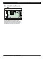
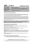
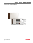
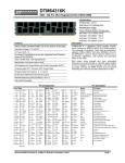
DX4010i
Installation Instructions
EN
RS-232 Serial Interface
Module
DX4010i | Installation Instructions | Trademarks
Trademarks
•
2
BlackBox® is either a registered trademark or a
trademark of BlackBox Corporation in the United
States and/or other countries.
Bosch Security Systems, Inc. | 1/05 | 4998141106C
DX4010i | Installation Instructions | Contents
Contents
1.0
2.0
3.0
4.0
5.0
5.1
5.2
5.3
6.0
7.0
8.0
General Information .......................................4
Specifications ....................................................4
Installation Standards .....................................4
Wiring .................................................................5
DX4010i Jumper Pin Settings ........................6
Enable LED Jumper Pins (P2)...........................6
DB9 Ground Enable Pins (P1) ..........................6
Address DIP Switches ........................................7
Remote Programming Direct Connection .7
DB9 DTE RS-232 Connector (P6)................10
RJ-16 Data Bus Connector (P3)....................11
Figures
Figure 1:
Figure 2:
Figure 3:
Figure 4:
Figure 5:
Figure 6:
Figure 7:
Figure 8:
Figure 9:
DX4010i PCB Layout .................................4
Control Panel Connections ........................5
External Power Supply Connections ........5
Serial Device Connections .........................5
Parallel Device Connections ......................6
P2 Jumper Settings ......................................6
DIP Switch Location/Orientation .............7
DB9 Connector Layout ............................10
P3 Connector .............................................11
Tables
Table 1:
Table 2:
Table 3:
Table 4:
Table 5:
DX4010i Specifications...............................4
Diagnostic LED Functions .........................6
Option Bus Address DIP Switch Settings.8
SDI Bus Address DIP Switch Settings ......9
Alternate Wiring Configuration...............10
Bosch Security Systems, Inc. | 1/05 | 4998141106C
3
DX4010i | Installation Instructions | 1.0
General Information
1.0 General Information
Figure 1: DX4010i Component Layout
The DX4010i is a data terminal equipment (DTE)
configured RS-232 serial device interface (SDI) module
designed to operate with compatible control panels. It
connects to the control panel through the option or
SDI data bus.
The DX4010i is used to connect a PC with RPS, BIS,
PC 9000, CMS 7000, or other third party software that
uses a serial conncetion to the supported control
panels. The module also supports a serial printer (or
parallel printer with a convertor box) for control panels
that support a serial printer. The compatibility lists in
Table 1 show support information.
2.0 Specifications
Table 1: DX4010i Specifications
Operating
Voltage
Current Draw
Communication
Configuration
12 VDC
50 mA nominal, 55 mA with diagnostic
LEDs enabled
Programmable through the control
panel. Refer to the appropriate control
panel programming instructions.
5
LED
E NABL E
Application
Compatibility
4
Tx R x
SER
P2
P6
7
3
P1
2
DB9 GND
ENA BLE
P3
1
1234567-
DB9 GND enable pins (P1)
RJ-16 data bus connector (P3)
Data bus (TS1)
Address DIP switches (S1)
Diagnostic LEDs
Diagnostic LED enable pins (P2)
DB9 DTE RS-232 connector (P6)
3.0 Installation Standards
Failure to follow the instructions in this
manual can result in personal injury or
damage to the equipment.
The DX4010i contains static-sensitive
components and must be handled with
care. Follow anti-static procedures when
handling the modules.
0°C to +50°C (+32°F to +122°F)
5 to 85% @ +30°C (+86°F)
non-condensing
Option bus control panels: D6412,
D4412, DS7240, DS7220, DS7400Xi
(v2.02 or higher)
SDI bus control panels (v6.0 or higher):
D9412G, D7412G, D7212G, D9124,
D9112, D7412, and D7212
RPS: supported on all compatible
control panels
PC 9000: supported on SDI Bus
control panels (D9412G, D7412G,
D7212G, D9112, D7412, and D7212)
BIS: supported on SDI Bus control
panels, v6.3 and higher (D9412G,
D7412G, and D7212G)
CMS 7000: supported on DS7400Xi
Control Panels set at Mode 18 (v3.09
or higher)
Printers: supported on compatible
Option Bus control panel
Rx Tx
BUS
4
The baud rate for the printer output on a
DS7400Xi must be greater than 300 baud.
Operating
Temperature
Relative
Humidity
Control Panel
Compatibility
6
Test according to NFPA 72 if used in fire
applications.
1.
2.
3.
4.
5.
6.
Disconnect power to the control panel by
unplugging the transformer and removing the red
battery lead.
Remove screws from enclosure cover to access the
DX4010i board.
Connect circuit wiring and install jumper pins.
Refer to Section 4.0 Wiring on page 5.
Replace enclosure cover.
Connect a serial cable to the serial device. Refer to
Section 7.0 DB9 DTE RS-232 Connector (P6) on
page 10.
Reapply power to the control panel.
Bosch Security Systems, Inc. | 1/05 | 4998141106C
DX4010i | Installation Instructions | 4.0
4.0 Wiring
Figure 3: External Power Supply Connections
Remove all power to the control panel (AC
and standby battery) before making or
breaking any connections. Failure to do so
can result in personal injury or damage to
the equipment.
1
2
3
4
Wire Length Restrictions
5
•
0.8 mm (#22 AWG): 305 m (1000 ft)
•
1.2 mm (#18 AWG): 610 m (2000 ft)
6
SDI wiring is limited to 305 m (1000 ft).
Connect the DX4010i to the control panel data and
auxiliary power sources as shown in Figure 2.
Figure 2: Control Panel Connections
2
1
123456-
Wiring
B
3
G
4
Y
5
R
6
+
-
7
1234567-
DX4010i data bus
Control panel data bus
Option AUX common/SDI common (black)
Option data/SDI B (green)
Option data/SDI A (yellow)
Option AUX power +/SDI power (red)
External 12 VDC power supply
Figure 4 shows serial device-to-DX4010i connections
using the DB9 DTE RS-232 connector (P6).
Figure 4: Serial Device Connections
DX4010i data bus
Control panel data bus
Option AUX common/SDI common (black)
Option data/SDI B (green)
Option data/SDI A (yellow)
Option AUX power +/SDI power (red)
LED
ENABLE
Rx Tx
BUS
Tx Rx
SER
P2
P6
P1
If an external 12 VDC power supply is used, wire as
shown in Figure 3.
DB9 GND
ENABLE
P3
1
1- Serial (RS-232) device such as a PC (with
RPS, BIS, PC9000, or other third party
application) or a serial printer for supported
control panels.
See Section 7.0 DB9 DTE RS-232
Connector (P6) on page 10 for additional
information.
Figure 5 shows a parallel printer connected to the serial
output of the DX4010i. This type of connection
requires the use of a serial to parallel converter, such as
the BlackBox PI045A serial to Centronics parallel
converter cable. The cable is available from
BlackBox® (www.blackbox.com).
Bosch Security Systems, Inc. | 1/05 | 4998141106C
5
DX4010i | Installation Instructions | 5.0
DX4010i Jumper Pin Settings
Figure 5: Parallel Device Connections
Figure 6: P2 Jumper Settings
LED
ENABLE
Rx Tx
BUS
Tx Rx
SER
1
P2
P6
LED
ENA BLE
R x Tx
B US
Tx R x
SE R
P2
P6
P1
DB9 GND
ENABLE
P3
P1
2
DB 9 G ND
ENAB L E
P3
2
1
1- Parallel converter cable box (BlackBox P/N:
PI045A
2- Parallel printer (compatible option bus control
panels only)
5.0 DX4010i Jumper Pin
Settings
5.1
4
1234-
3
Diagnostic LED enable pins (P2)
DB9 GND enable pins (P1)
Enabled
Disabled
Table 2: Diagnostic LED Functions
Enable LED Jumper Pins (P2)
Use the diagnostic LEDs for troubleshooting. To
enable the LEDs, place a jumper plug across the
jumper pins labeled P2.
Diagnostic LED
Function
BUS RX
Refer to Figure 6 for jumper pin settings.
BUS TX
SER RX
SER TX
Data bus receives data from control
panel
Data bus transmits data to control panel
RS-232 receives data from serial device
RS-232 transmits data to serial device
The DX4010i draws more current when the
diagnostic LEDs are enabled. Do not
enable the diagnostic LEDs under normal
operating conditions.
5.2
DB9 Ground Enable Pins (P1)
Some devices connected to the DB9 DTE RS-232
connector (P6) can cause a ground fault condition on
the control panel. If this occurs, removing the plug
across the P1 jumper pins can clear the ground fault
condition.
Some devices might still cause a ground
fault even if the P1 jumper plug is removed.
Refer to Figure 6 for jumper pin settings.
6
Bosch Security Systems, Inc. | 1/05 | 4998141106C
DX4010i | Installation Instructions | 6.0
5.3
Remote Programming Direct Connection
Address DIP Switches
The address DIP switches are used to assign an address
to the DX4010i.
Refer to Table 3 for DIP switch option bus address
settings.
Refer to Table 4 for DIP switch SDI bus address
settings.
Refer to Figure 7 for proper DIP switch orientation.
Figure 7: DIP Switch Location and Orientation
LED
ENAB LE
Rx Tx
BUS
1
Tx Rx
SER
6.0 Remote Programming
Direct Connection
The DX4010i can be used to create a local direct
connection for remote programming of a compatible
control panel.
Option Bus: Set the address DIP switches to
Address 0. Refer to Table 3 on page 8.
SDI Bus: Set the address DIP switches to Address 88.
Refer to Table 4 on page 9.
Consult your control panel’s installation guide for
specific wiring connections.
P2
P6
A DB9 to DB9 null-modem cable is
required when using the direct connection
method.
P1
DB9 G ND
E NABLE
P3
ON
3
1
2
3
4
5
6
1
2
4
8
16
32
7
2
8
64 128
4
1234-
Address DIP switches
ON position
OFF position
Address example (option bus Address 0)
Bosch Security Systems, Inc. | 1/05 | 4998141106C
7
DX4010i | Installation Instructions | 6.0
Remote Programming Direct Connection
Table 3: Option Bus Address DIP Switch Settings
DIP Switch Settings
DIP
Switches
Module
Address
0*
1
2
3
4
5
6
7
8
9
10
11
12
13**
14**
15
134
135
136
137
138
139
140
141
142
143
144
145
250
251
252
253
S1
S2
S3
S4
S5
S6
S7
S8
1
2
4
8
16
ON
OFF
ON
OFF
ON
OFF
ON
OFF
ON
OFF
ON
OFF
ON
OFF
ON
OFF
ON
OFF
ON
OFF
ON
OFF
ON
OFF
ON
OFF
ON
OFF
ON
OFF
ON
OFF
ON
ON
OFF
OFF
ON
ON
OFF
OFF
ON
ON
OFF
OFF
ON
ON
OFF
OFF
ON
ON
OFF
OFF
ON
ON
OFF
OFF
ON
ON
OFF
OFF
ON
ON
OFF
OFF
ON
ON
ON
ON
OFF
OFF
OFF
OFF
ON
ON
ON
ON
OFF
OFF
OFF
OFF
OFF
OFF
OFF
OFF
ON
ON
ON
ON
OFF
OFF
OFF
OFF
ON
ON
ON
ON
ON
ON
ON
ON
ON
ON
ON
ON
OFF
OFF
OFF
OFF
OFF
OFF
OFF
OFF
ON
ON
ON
ON
OFF
OFF
OFF
OFF
OFF
OFF
OFF
OFF
ON
ON
ON
ON
ON
ON
ON
ON
ON
ON
ON
ON
ON
ON
ON
ON
ON
ON
ON
ON
ON
ON
ON
ON
ON
ON
ON
ON
ON
ON
ON
ON
ON
ON
ON
ON
32
(Mode)
OFF
OFF
OFF
OFF
OFF
OFF
OFF
OFF
OFF
OFF
OFF
OFF
OFF
OFF
OFF
OFF
ON
ON
ON
ON
ON
ON
ON
ON
ON
ON
ON
ON
ON
ON
ON
ON
64
(Option/SDI)
ON
ON
ON
ON
ON
ON
ON
ON
ON
ON
ON
ON
ON
ON
ON
ON
ON
ON
ON
ON
ON
ON
ON
ON
ON
ON
ON
ON
ON
ON
ON
ON
128
(Checksum +1)
OFF
OFF
OFF
OFF
OFF
OFF
OFF
OFF
OFF
OFF
OFF
OFF
OFF
OFF
OFF
OFF
ON
ON
ON
ON
ON
ON
ON
ON
ON
ON
ON
ON
ON
ON
ON
ON
* Installer’s mode: Use for direct connection of remote programming and diagnostic tools.
** DS7412 emulation
The DS7400Xi (USA) only supports one DX4010i
Option bus control panels: D6412, D4412, DS7240, DS7220, DS7400Xi (v2.02 or higher).
8
Bosch Security Systems, Inc. | 1/05 | 4998141106C
DX4010i | Installation Instructions | 6.0
Remote Programming Direct Connection
Table 4: SDI Bus Address DIP Switch Settings
SDI DIP Switch Settings
SDI DIP
Switches
Module
Address
80*
81
82
83
84
85
86
87
88**
89
8A
8B
8C
8D
8E
8F
S1
S2
S3
S4
S5
S6
S7
S8
1
2
4
8
16
ON
OFF
ON
OFF
ON
OFF
ON
OFF
ON
OFF
ON
OFF
ON
OFF
ON
OFF
ON
ON
OFF
OFF
ON
ON
OFF
OFF
ON
ON
OFF
OFF
ON
ON
OFF
OFF
ON
ON
ON
ON
OFF
OFF
OFF
OFF
ON
ON
ON
ON
OFF
OFF
OFF
OFF
ON
ON
ON
ON
ON
ON
ON
ON
OFF
OFF
OFF
OFF
OFF
OFF
OFF
OFF
OFF
OFF
OFF
OFF
OFF
OFF
OFF
OFF
OFF
OFF
OFF
OFF
OFF
OFF
OFF
OFF
32
(Mode)
OFF
OFF
OFF
OFF
OFF
OFF
OFF
OFF
OFF
OFF
OFF
OFF
OFF
OFF
OFF
OFF
64
(Option/SDI)
OFF
OFF
OFF
OFF
OFF
OFF
OFF
OFF
OFF
OFF
OFF
OFF
OFF
OFF
OFF
OFF
128
(Checksum +1)
OFF
OFF
OFF
OFF
OFF
OFF
OFF
OFF
OFF
OFF
OFF
OFF
OFF
OFF
OFF
OFF
Positions 5, 6, and 8 are not used for SDI bus.
* Used for BIS, PC 9000, and other third party applications.
** Used for RPS and alternate communication.
SDI bus control panels (v6.0 or higher): D9412G, D7412G, D7212G, D9124, D9112, D7412, and
D7212.
Bosch Security Systems, Inc. | 1/05 | 4998141106C
9
DX4010i | Installation Instructions | 7.0
7.0
DB9 DTE RS-232 Connector (P6)
DB9 DTE RS-232
Connector (P6)
Figure 8: DB9 Connector Layout
1
The DX4010i serial port is wired as a DTE device.
•
If the connected device is a data carrier
equipment (DCE) device (most common, such
as an external modem), a straight through 9-pin
to 9-pin, or (DTE to DCE) 9-pin to 25-pin cable
may be used.
•
If the connected device is a DTE device (such as
a PC serial port), a null-modem (DTE to DTE)
9-pin to 9-pin, or null-modem 9-pin to 25-pin
cable is required.
Consult the operating manual provided with your
compatible device for wiring requirements.
If you are using an alternate configuration, you must
make a custom cable (refer to Figure 8 and Table 5).
6
12345-
DCD
RxD
TxD
DTR
GND
3
7
4
5
8
9
6789-
DSR
RTS
CTS
RI
Table 5: Alternate Wiring Configuration
DX4010i
9-Pin DTE
Connector
1: DCD
(not used)
2: RxD
3: TxD
4: DTR
5: GND
6: DSR
7: RTS
8: CTS
9: RI
(not used)
10
2
DCE
(9-pin)
DTE
(9-pin)
DCE
(25-pin)
DTE
(25-pin)
1: DCD
1: DCD
8: DCD
8: DCD
2: RxD
3: TxD
4: DTR
5: GND
6: DSR
7: RTS
8: CTS
9: RI
3: TxD
2: RxD
6: DSR
5: GND
4: DTR
8: CTS
7: RTS
9: RI
3: RxD
2: TxD
20: DTR
7: GND
6: DSR
4: RTS
5: CTS
22: RI
2: TxD
3: RxD
6: DSR
7: GND
20: DTR
5: CTS
4: RTS
22: RI
Bosch Security Systems, Inc. | 1/05 | 4998141106C
DX4010i | Installation Instructions | 8.0
RJ-16 Data Bus Connector (P3)
8.0 RJ-16 Data Bus Connector
(P3)
Figure 9: P3 Connector
LED
ENABLE
Rx Tx
BUS
Tx Rx
SER
P2
P6
P1
1
DB9 GND
ENABLE
P3
1- RJ-16 data bus connector (P3)
For remote programming connection, use one of the
two cables supplied: RJ-16 to molex for control
panels with the data bus provided on a header (such
as the D6412 or DS7240) or the RJ-16 to spade lugs
for terminal strip connections (such as the D9412).
Bosch Security Systems, Inc. | 1/05 | 4998141106C
11
Bosch Security Systems
130 Perinton Parkway
Fairport, NY 14450-9199
Customer Service: (800) 289-0096
Technical Support: (888) 886-6189
Bosch Security Systems
130 Perinton Parkway
Faiport, NY 14450-9199 USA
Customer Service: (800) 538-5807; Technical Support: (888) 886-6189
© 2005 Bosch Security Systems
4998141106C