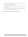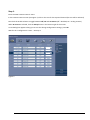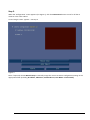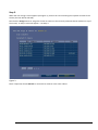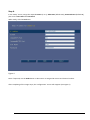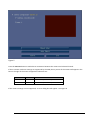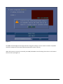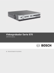
1
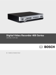
Security Systems
Addendum
DVR670 Installation and Operation manual AM18-Q0617
Security Warning
The remote system access feature, designed to allow users to view their video via a PC or phone, may
compromise their security devices and expose them to malicious use.
To avoid putting your devices and personal information at risk, always consult your network specialist for advice
on network security infrastructure (i.e. MAC filtering, Access Control List).
Bosch accepts no responsibility for possible damage caused by unauthorised access.
iPhone ‘DVR Viewer’ APP
With firmware v2.1.x the iPhone ‘DVR Viewer’ APP version 1.0.3 or higher must be used.
IP camera integration from firmware v2.1 onwards
Introduction
This addendum describes how to integrate an IP camera in the DVR 670 Series (firmware 2.1 onwards).
The main requirements and restrictions are:
•
Input from a maximum 4 SD Bosch IP cameras can be recorded on a single DVR 670. Using IP cameras
means the DVR can manage fewer analog cameras; i.e. if you connect 1 SD camera, you will lose 1 analog
camera.
•
The DVR does not directly control the camera stream (IPS or resolution) and will only record the available
stream (configured on the camera).
•
Event triggered recording (motion and/or input) is not supported for the connected IP cameras.
•
Live and playback video of connected IP cameras (SD streams) can be shown on a local DVR monitor A.
•
Viewing of IP camera on Mon. B is not supported.
•
Video of connected IP camera can also be shown via Web pages and supported PC applications.
•
PTZ and fixed SD cameras can be recorded, however only standard PTZ commands and presets (go to, set,
clear) are available (i.e. there is no AUX, iris and focus control). To enable PTZ for IP cameras please select
RS232 or RS485 PTZ communication protocol for the selected channel.
•
Supported resolutions :
IPS
Resolution
NTSC
≤ 30 IPS
≤ 702 x 576 (SD/D1/4CIF)
PAL
≤ 25 IPS
≤ 702 x 480 (SD/D1/4CIF)
P AG E 1 O F 9
•
An HD camera can be used for recording SD stream 2 for eventual recording and playback on the DVR.
Display the live HD stream with Bosch Video Client.
•
Live and recorded audio from an IP camera is not supported.
•
The IP feature will be available on a DVR 670 platform using a simple FW upgrade, and is free of charge
(no licence required).
•
Previous IP cameras firmware 5.60 is not supported for this release. Please use 5.52, 5.70 or 5.80.
•
To display the archived video from the IP cameras you need to use the latest Archive Player v1.0.10.1.
This version of the player is incorporate in the DVR firmware v2.1
See the following steps (1 to 4) to add an IP camera to the DVR670 v2.1
P AG E 2 O F 9
Step 1.
Enter the DVR ‘Camera-Camera’ menu.
In the Camera-Camera screen (see Figure 1) click on the row for the required channel (the row will be selected).
Now click the Enable column to toggle between Off, On and IP camera (Off = disabled; On = analog camera).
When IP camera is selected, click the Setup button in the bottom right of the screen.
A new dialog box appears asking you to save the change configuration settings; press OK.
Wait for the ‘Configuration’ screen – see Step 2.
Figure 1
P AG E 3 O F 9
Step 2.
When the ‘Configuration’ screen appears (see Figure 2), click the Auto Detect button to scan for all the IP
cameras in the same subnet.
A new ‘Assign’ screen appears – see Step 3.
Figure 2
Note: If required, choose Manual Setup to manually assign the correct IP camera configuration settings in the
appropriate fields (including IP Address, Video Port, Command Port, User Name and Password).
P AG E 4 O F 9
Step 3.
When the new ‘Assign’ screen appears (see Figure 3), click on the row containing the required IP camera from
the list (the row will be selected).
Now click the Assign button to assign the chosen IP camera to the currently selected channel (shown on top of
the screen). A ‘Setup’ screen will appear – see Step 4.
Figure 3
Note: If required, choose Refresh to rescan the IP cameras in the same subnet.
P AG E 5 O F 9
Step 4.
In the ‘Setup’ screen, assign the required Stream (1 or 2), Video Port (default 554), Command Port (default 80),
plus correct User Name and Password.
When ready, click the OK button.
Figure 4
Note: If required, use the Undo button to disconnect an assigned IP camera and channel number.
After completing all the assign steps, the ‘Configuration’ screen will reappear (see Figure 5).
P AG E 6 O F 9
Figure 5
Press the Connect button to make the IP connection between the camera and selected channel.
If the IP camera resolution settings are supported by the DVR, then a picture of the camera will appear in the
box on the right of the screen. Supported resolutions are:
IPS
Resolution
NTSC
≤ 30 IPS
≤ 702 x 576 (SD/D1/4CIF)
PAL
≤ 25 IPS
≤ 702 x 480 (SD/D1/4CIF)
If the camera settings are not supported, an error dialog box will appear - see Figure 6.
P AG E 7 O F 9
Figure 6
Click OK to acknowledge the message and then change the settings in the IP camera to obtain acceptable
resolution settings (see the camera Operator Manual for how to do this).
When the camera is correctly connected, press Exit, then OK to save all settings and return to the CameraCamera screen (see Figure 1).
P AG E 8 O F 9
© Bosch Security Systems, 2013
Version 1.1 2013.06
Doc. No.: AM18-Q656
Subject to change
P AG E 9 O F 9