1
June 2002
DEMOLITION HAMMER
INDUSTRIAL
Model 0611318739
11318EVS
150
2.1- 2.3 mm
171
16
142 167 121
73
28
856
26
Pos. 821
31
Z
23
165
144
162
143
81
57
22
4
835
21
75
25
891
53
200
160
821
167
154 142
18
818
195
121
874
174
17
177
72
808
116
Secure with Loctite
138
69
37
203
174
174
B
840
C
150
7
126
104
87
141
145
95
Z
137
134
135
6
D
5
803
86
A
38
884
898
85
138
Black
Red
14
803
84
895
15
113
Spring Tension
27
175
803
34
176
111
13
112
811
817
42
D 80
2
131
D
1
135
B
172
= Pos. 897
C A
43
C
9
S-B Power Tool Company Chicago IL 60646-5999
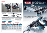
11318EVS DEMOLITION HAMMER
Pos.
Part Number
Description {Qty.}
F/C
Pos.
Part Number
Description {Qty.}
1
2
4
1 615 102 155
1 614 220 163
1 617 200 095
71
22
15
5
6
7
9
13
14
15
16
17
18
21
22
23
25
26
27
28
31
34
37
38
42
1 614 461 035
1 610 703 056
1 601 302 019
1 611 110 C62
1 610 900 026
1 610 905 028
1 616 610 090
1 610 499 041
1 610 241 000
1 614 601 030
1 610 508 038
1 610 591 030
1 610 520 001
1 612 300 036
1 610 290 076
1 610 591 028
1 614 621 000
1 610 290 049
1 610 516 013
1 615 500 321
1 615 190 105
1 614 336 046
134
135
137
138
141
142
143
144
145
150
154
160
162
165
167
171
172
174
175
176
177
195
200
203
803
2 910 110 116
1 614 431 031
2 916 699 130
1 611 015 050
1 610 290 066
1 610 290 061
1 614 601 021
1 610 251 006
1 610 119 012
1 610 210 127
2 916 660 024
1 610 210 172
1 610 210 091
1 610 210 153
1 610 290 062
1 613 435 014
1 613 435 013
1 613 435 012
2 912 401 018
1 613 435 012
1 603 435 051
1 613 435 020
1 610 284 000
1 610 322 009
1 614 011 107
43
53
57
69
72
73
75
80
81
84
85
86
87
95
104
111
112
113
116
121
126
131
1 615 500 322
1 610 102 054
1 618 710 073
1 610 099 005
1 616 317 062
1 615 500 319
1 615 132 087
1 617 233 038
1 615 132 088
1 612 025 054
1 618 040 074
1 613 490 001
1 611 316 019
1 610 210 173
1 610 210 095
1 610 290 064
1 613 300 008
1 613 435 009
1 610 311 017
1 610 328 018
2 910 211 019
1 611 110 C56
Motor Housing
Field
Switch
w/pos. 818
Cord
Strain Relief
Clamp
Label
Ball Bearing
Ball Bearing
Fan
Sleeve
Washer
Retaining Ring
Dust Shield
Sleeve
Stop Sleeve
Locking Cog {2}
Disc
Air Deflector
Spring
Bushing
Flange
Bracket
Cover
Bush Holder
w/pos. 811, 817
Cover
Washer
Striker
Bracket
Eccentric Gear
Gear Housing Cover
Handle
Speed Control
Handle Cover
Auxiliary Handle
Clamp Holder
T-Bolt
Clamping Band
O-Ring
O-Ring
Bushing
Nut
Screw {2}
Bushing
Bushing
Screw
Label
808
811
817
818
821
1 611 104 999
1 617 014 135
1 614 652 004
2 910 011 082
1 617 000 835
835
1 617 000 432
840
1 617 000 846
856
1 617 000 836
874
884
1 617 000 422
1 612 025 055
891
1 617 000 853
895
897
1 615 430 019
1 617 000 431
898
1 615 437 512
Screw
89
Cable
10
Lock Washer
65
Gasket
79
Seal
77
Seal
77
Spring Ring
89
Washer
86
Retaining Ring
89
O-Ring
78
Retaining Ring
89
Ring
9
O-Ring
78
O-Ring
42
Seal
77
Screw {4}
89
Screw {4}
89
Screw {6}
89
Screw {2}
89
Screw {2}
89
Screw {2}
89
Screw {2}
89
Bellows
9
Washer {2}
65
Armature Assembly
AW
w/pos. 13, 14, 15, 95,
111, 112, 141, 145
Nameplate
9
Brush Set
26
Brush Spring {2}
27
Screw {2}
89
Bushing Assembly
82
w/pos. 121, 142, 167
Guide Tube Assembly
43
w/pos. 25
Gear Housing Assembly 72
w/pos. 95,104,141,145,150
Piston Assembly
47
w/pos. 165
Plate
9
Auxiliary Handle
9
w/pos. 84, 85, 86, 87
Shock Absorber
9
w/pos. 200
Oil
1
Service Pack
78
w/pos. 21, 25, 138, 143,
162, 165, 811
Oil w/pos. 138
1
11
11
89
9
60
61
23
86
65
89
92
86
86
86
86
24
86
82
9
9
9
25
70
65
44
62
34
70
74
17
74
9
80
80
80
78
78
82
89
89
82
82
89
9
Service Notes:
+ = Not Illustrated
* = As Required
F/C = Failure Code
AW = Refer to AW Labor Time Chart
F/C