1
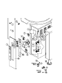
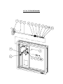
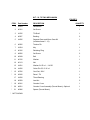
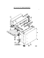
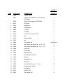
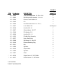
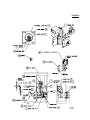
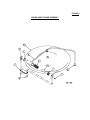
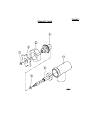
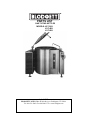
PARTS LIST
GAS TILTING KETTLES
MODELS: KLT-20G
KLT-40G
KLT-60G
April 6, 2007
BLODGETT OVEN CO ▪ 44 lakeside Ave ▪ Burlington, VT 05446
Tel. 800-331-5842 ▪ Fax 802-860-3732 ▪ www.blodgett.com
FIGURE 1
ITEM
**
**
Part Number
DESCRIPTION
1
40955
Pilot Light - Green 24V
1
2
42175
Instruction Label
1
3
40795
Low Water Control Mounting Bracket
1
4
40466
Probe, 9 ¼” (20 Gallon)
1
40467
Probe, 9 ¾” (30, 40, 60 Gallon)
1
5
40542
Low Water Cut Off Control
1
6
40046
Thermostat
1
7
42548
Poly Panel
1
8
41889
Power Switch
1
9
42415
Pilot Light - Red
1
10
42430
Pilot Light - Amber
1
11
41006
Dial
1
12
42179
Pressure Gauge Bracket
1
13
40907
Pressure Gauge
1
14
42177
Mounting Bracket (30, 40 Gallon only)
1
42178
Mounting Bracket (20, 60 Gallon only)
1
41077
Sight Glass Assembly
1
41741
Rods
2
41743
Washer - Rubber
2
41744
Washer - Brass
2
16
42443
Pressure Switch
1
17
40613
Relief Valve
1
18
41474
Flanged Foot
2
19
40708
Terminal Block Section
2
20
40707
End Section
1
21
40938
Interlock Switch
1
22
40743
Ground Lug
1
23
40548
Vent
1
15
QUANTITY
FIGURE 1
ITEM
* **
* **
**
Part Number
DESCRIPTION
40251
Combustion Chamber (20 Gallon)
1
40252
Combustion Chamber (30, 40 Gallon)
1
40253
Combustion Chamber (60 Gallon)
1
25
40033
Recessed Control Panel
1
26
40376
Bottom Cover (20 Gallon)
1
40377
Bottom Cover (30, 40 Gallon)
1
40378
Bottom Cover (60 Gallon)
1
40326
Control Panel (20, 30, 40 Gallon)
1
40329
Control Panel (60 Gallon)
1
24
27
* NOT SHOWN.
** SELECT AS REQUIRED.
QUANTITY
KLT-20, TILTING MECHANISM
KLT - 20, TILTING MECHANISM
FIGURE 2
ITEM
Part Number
DESCRIPTION
1
41554
Handwheel
1
2
40101
Set Screw
1
3
41235
Tilt Shaft
1
4
40367
Bushing
2
5
41095
Segment Gear and Worm Gear Kit
(Includes items 6 - 12)
1
6
40266
Tension Pin
1
7
41564
Key
1
8
40126
Retaining Ring
1
9
40082
Set Screw
2
10
40249
Bolt
1
11
40132
Washer
1
12
40113
Nut
1
13
41091
Washer 3/4 ID x 1 - 1/4 OD
1
14
41092
Cotter Pin S.S. 3/16 x 1
1
*
15
42706
Cord Set, 120V
1
*
16
42342
Decal - Tilt
1
17
41090
Thrust Bearing
2
18
40258
Jam Nut
2
*
19
40241
Console Cover
1
*
20
40621
Console Cover Assembly (Faucet Mount), Optional
1
*
21
40496
Spacer (Faucet Mount)
1
* NOT SHOWN.
QUANTITY
KLT 20, 40, 60, TILT CONSOLE AND PARTS
FIGURE 3
FIGURE 3
ITEM
Part Number
DESCRIPTION
QUANTITY
43396
Console Cover
1
*
40621
Console Cover Assembly (Faucet Mount),
OPTIONAL.
1
*
40496
Spacer (Faucet Mount), OPTIONAL.
1
2
40101
Set Screw
1
3
41554
Handwheel
1
4
41084
Front Bearing
1
5
42862
Tilt Shaft
1
6
42342
Tilt Label
1
7
40169
Trunnion Housing Assembly
1
8
41564
Key
1
9
40126
Retaining Ring
1
10
40075
Arm
1
11
43004
Flat Washer 3/8
12
43397
Hex Socket Cap Screw, 3/8 - 16 x 2 - 1/8
1
13
43398
Hex Socket Cap Screw, 3/8 - 16 x 1 - 1/4
8
14
41088
Chain Link
1
15
41232
Screw Jack
1
16
43399
Base Assembly
1
17
43400
Base Bracket Assembly
1
18
41083
Bearing
2
19
41474
Adjustable Foot
2
20
43401
Side Panel
1
21
40076
Truss HD Slot Screw, 10 - 32 x ½
10
22
40708
Terminal Block Section
2
23
40707
End Section
1
24
42013
Earth ID Tag
1
25
43003
Flat Washer #10
2
**
1
As Required
FIGURE 3
ITEM
Part Number
DESCRIPTION
26
43402
Truss HD Phillips Drive, 10 - 32 x 1-1/4
2
27
43403
RD HD Slot Drive Screws 8 - 32 x 1/4
3
28
43404
External Tooth Washer # 8
3
29
43405
Pin
1
30
43406
Hex Socket Set Screw 1/4 - 20 x ½
1
31
43407
Lock Washer 3/8
As Required
32
40108
Hex Nut 3/8 - 16
7
33
40887
Grease Nipple, 1/8 NPT
1
34
43408
Flat Washer 5/16
2
35
40099
Hex Nut 5/16 - 18
2
36
41233
Flexible Shaft Assembly
1
37
42797
Nylon Shaft Guide
2
38
43409
Set Screw 1/4 - 28 x 3/8
1
39
43410
External Retaining Ring
1
40
43411
Key
2
41
41086
Sprocket
1
42
43412
Output Shaft
1
43
41085
Sprocket
1
44
41087
Chain
1
*
45
40730
Single Faucet 12", OPTIONAL
1
*
45
40727
Double Faucet 12", OPTIONAL
1
* NOT SHOWN.
** SELECT AS REQUIRED.
QUANTITY
FIGURE 4
FIGURE 4
ITEM
**
**
**
Part Number
DESCRIPTION
20
42589
Complete Burner Assembly, Natural Gas
1
42592
Complete Burner Assembly, LP Gas
1
42588
Complete Burner Assembly, Natural Gas
1
42591
Complete Burner Assembly, LP Gas
1
42593
Complete Burner Assembly, Natural Gas
1
42590
Complete Burner Assembly, LP Gas
1
2
40503
DSI Module
1
1
1
3
42450
Ignition Wire 18"
1
1
1
4
41861
Fuse, 250V, 3 Amp.
1
1
1
5
40505
Transformer, 120/24V, 50/60, 30 VA
1
1
1
6
42445
Motor/Blower, 115V/50/60 HZ
1
1
1
7
42595
Control/Ignition Module, Wire Harness
1
1
1
8
42981
Air Shutter Assembly
1
1
1
9
42983
Venturi Assembly
1
1
1
10
42449
Electrode Assembly
1
1
1
11
42984
Electrode Mounting Bracket
1
1
1
12
42986
Adaptor Bushing 7/8"
1
1
1
13
42987
Control Box with Strap
1
1
1
14
42988
Control Box Lid
1
1
1
15
42989
Tube/Housing 6"
1
1
1
16
42990
Flange Gasket 6-1/2" Square
1
1
1
17
42980
Adj. Flange Assembly, 6-1/2" Square
1
1
1
18
41107
Gas Valve (Natural/L.P.)
1
1
1
19
42975
Orifice #19, Natural Gas
1
42978
Orifice #30, L.P. Gas
1
42974
Orifice #13, Natural Gas
1
42977
Orifice #27, L.P. Gas
1
42979
Orifice #7, Natural Gas
1
19
42976
Orifice #23, L.P. Gas
1
20
42982
Orifice Holder
1
1
1
21
41804
Gas Flex Tube
1
1
1
22
40938
Interlock Switch
1
1
1
1
30
40
60
FIGURE 4
ITEM
* **
Part Number
DESCRIPTION
20
30
40
60
23
40169
Trunnion Housing Assembly
1
1
1
24
40242
Console Cover
1
1
1
40243
Console Cover - Hinge Mount
1
1
1
25
40167
Console Nozzle Assembly
1
1
1
26
40168
Nozzle Cover
1
1
1
27
42547
Gas Supply Pipe Assembly
1
1
1
28
42594
Hex Bushing, 1/2 x 3/4
2
2
2
* NOT SHOWN.
** SELECT AS REQUIRED.
FIGURE 5
SPRING ASSIST HINGE ASSEMBLY
FIGURE 5
SPRING ASSIST HINGE ASSEMBLY
ITEM
**
**
**
Part Number
DESCRIPTION
42112
HINGE ASSEMBLY
1
41543
Lock Pin
1
2
41546
End Lock Plate
1
3
43106
Stationary Disc
1
4
41100
Core
1
5
41526
Spring
1
6
41538
Handle Assembly (20 Gallon)
1
41539
Handle Assembly (30, 40 Gallon)
1
41531
Handle Assembly (60 Gallon)
1
7
43107
Rotary Disc
1
8
41520
End Stop Plate
1
9
40098
Cap Screws
4
10
40259
Knob
1
11
42713
Hinge Support Riser (20, 30, 40 Gal.)
1
42714
Hinge Support Riser (60 Gal.)
1
40017
Cover, 20 Gallon Kettle
1
41514
Cover, 30-40 Gallon Kettle
1
41515
Cover, 60 Gallon Kettle
1
12
** SELECT AS REQUIRED.
QUANTITY
FIGURE 7
DRAW-OFF VALVE
FIGURE 7
ITEM
Part Number
DESCRIPTION
40553
1 -1/2" DRAW-OFF VALVE ASSEMBLY
1
41809
Acorn Nut 10-24 UNC
1
2
40662
Handle, Stainless Steel
1
3
40560
Bonnet
1
4
40559
Gland Nut
1
5
40562
“O” Ring
1
6
40561
Stem Assembly
1
7
43246
Valve Body
1
ITEM
QUANTITY
Part Number
DESCRIPTION
40554
2" DRAW OFF-VALVE ASSEMBLY
1
41809
Acorn Nut 10-24 UNC
1
2
40662
Handle, Stainless Steel
1
3
40564
Bonnet
1
4
40563
Gland Nut
1
5
40566
“O” Ring
1
6
40565
Stem Assembly
1
7
42481
Valve Body
1
Part Number
DESCRIPTION
40556
3" DRAW-OFF VALVE ASSEMBLY
1
40567
Acorn Nut, 7/16 - 14 UNC
1
2
40568
Handle, Stainless Steel
1
ITEM
QUANTITY
QUANTITY
3
40570
Bonnet
1
4
40569
Gland Nut
1
5
40572
“O” Ring
1
6
40571
Stem Assembly
1
7
43248
Valve Body
1